NISSAN NAVARA 2005 Repair Workshop Manual
NAVARA 2005
NISSAN
NISSAN
https://www.carmanualsonline.info/img/5/57362/w960_57362-0.png
NISSAN NAVARA 2005 Repair Workshop Manual
Trending: driver seat adjustment, EC_main, coolant level, timing belt, automatic transmission fluid, air condition, wheel size
Page 2151 of 3171
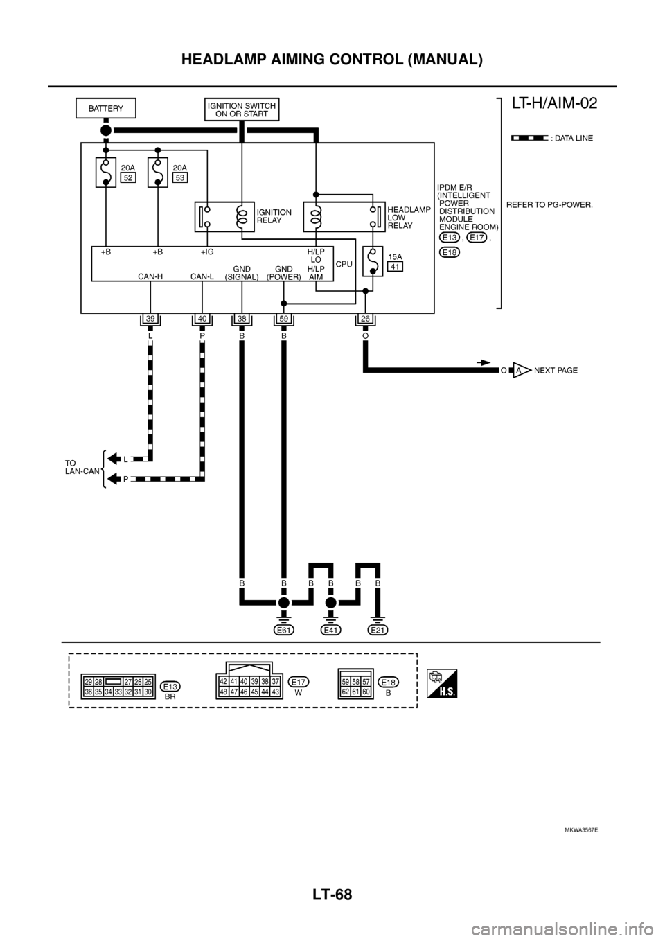
LT-68
HEADLAMP AIMING CONTROL (MANUAL)
MKWA3567E
Page 2152 of 3171
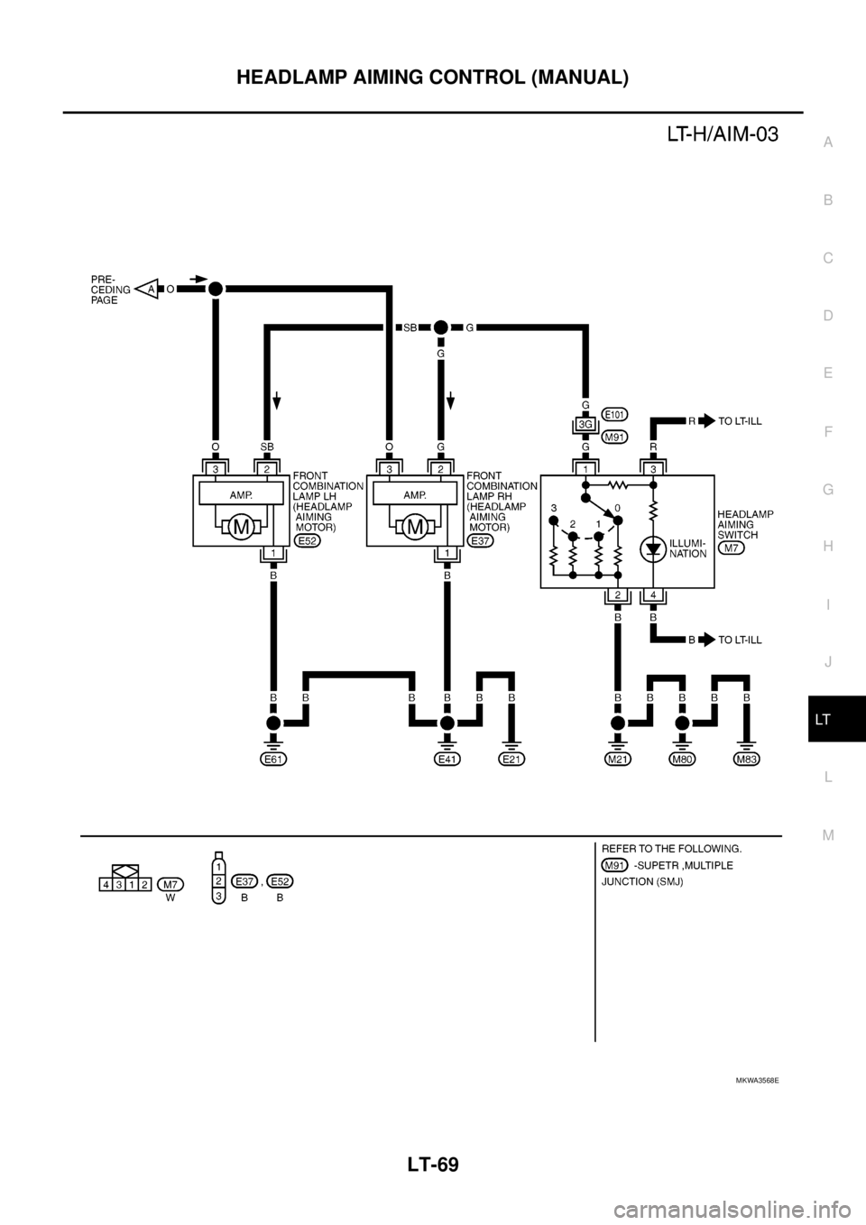
HEADLAMP AIMING CONTROL (MANUAL)
LT-69
C
D
E
F
G
H
I
J
L
MA
B
LT
MKWA3568E
Page 2153 of 3171
LT-70
HEADLAMP AIMING CONTROL (MANUAL)
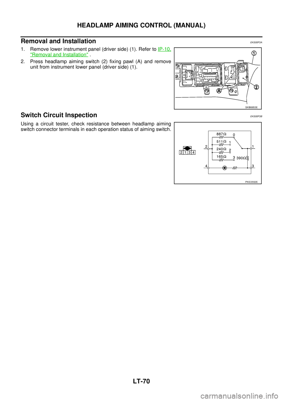
Removal and Installation
EKS00P3A
1. Remove lower instrument panel (driver side) (1). Refer toIP-10,
"Removal and Installation".
2. Press headlamp aiming switch (2) fixing pawl (A) and remove
unit from instrument lower panel (driver side) (1).
Switch Circuit InspectionEKS00P3B
Using a circuit tester, check resistance between headlamp aiming
switch connector terminals in each operation status of aiming switch.
SKIB6853E
PKIC0552E
Page 2154 of 3171
FRONT FOG LAMP
LT-71
C
D
E
F
G
H
I
J
L
MA
B
LT
FRONT FOG LAMPPFP:26150
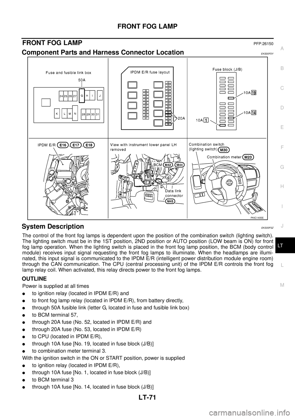
Component Parts and Harness Connector LocationEKS00P3Y
System DescriptionEKS00P3Z
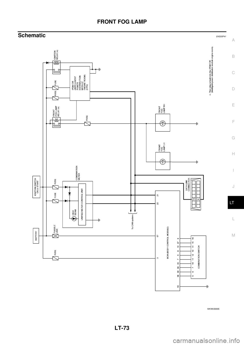
The control of the front fog lamps is dependent upon the position of the combination switch (lighting switch).
The lighting switch must be in the 1ST position, 2ND position or AUTO position (LOW beam is ON) for front
fog lamp operation. When the lighting switch is placed in the front fog lamp position, the BCM (body control
module) receives input signal requesting the front fog lamps to illuminate. When the headlamps are illumi-
nated, this input signal is communicated to the IPDM E/R (intelligent power distribution module engine room)
through the CAN communication. The CPU (central processing unit) of the IPDM E/R controls the front fog
lamp relay coil. When activated, this relay directs power to the front fog lamps.
OUTLINE
Power is supplied at all times
lto ignition relay (located in IPDM E/R) and
lto front fog lamp relay (located in IPDM E/R), from battery directly,
lthrough 50A fusible link (letter G, located in fuse and fusible link box)
lto BCM terminal 57,
lthrough 20A fuse (No. 52, located in IPDM E/R) and
lthrough 20A fuse (No. 53, located in IPDM E/R)
lto CPU (located in IPDM E/R),
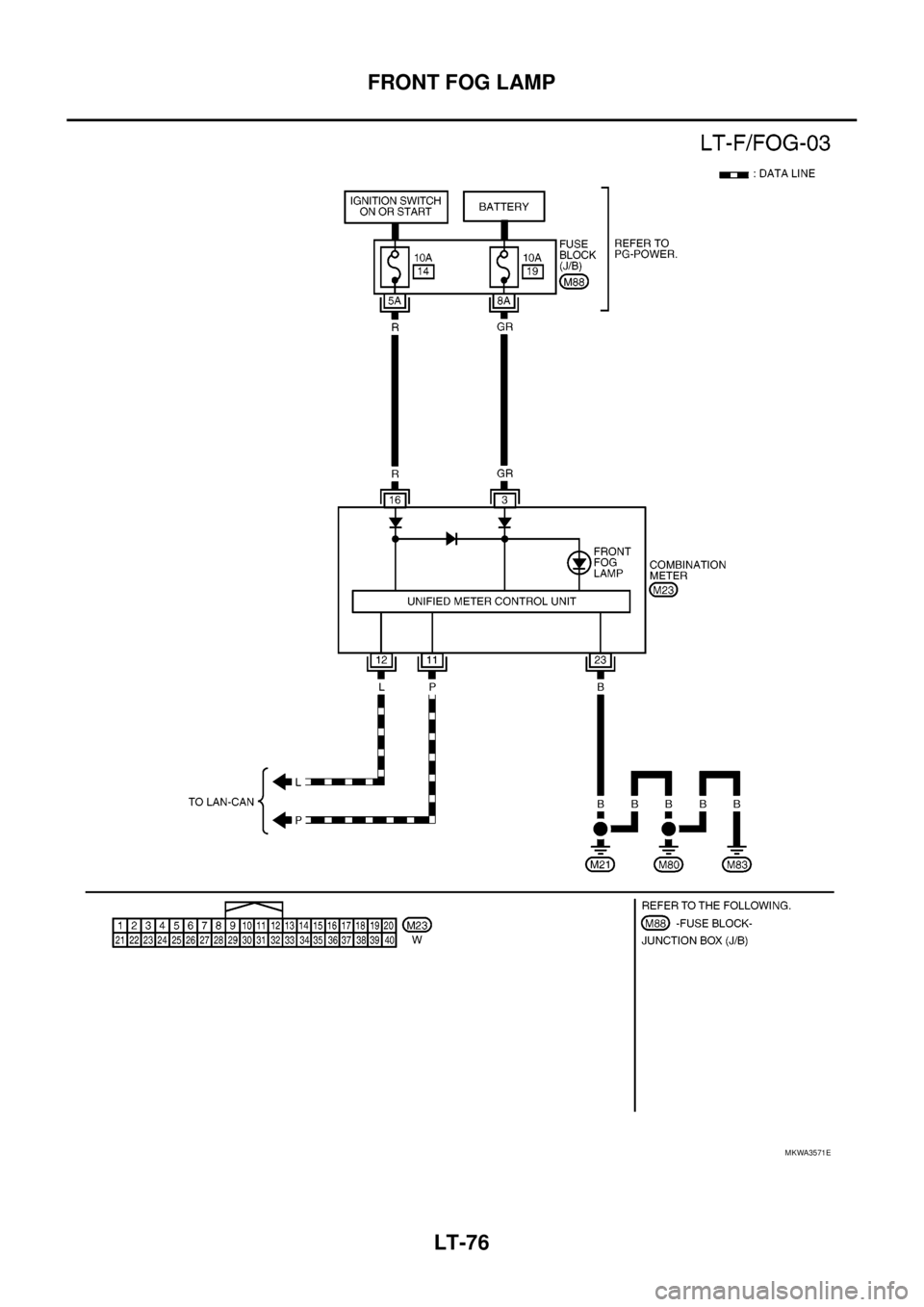
lthrough 10A fuse [No. 19, located in fuse block (J/B)]
lto combination meter terminal 3.
With the ignition switch in the ON or START position, power is supplied
lto ignition relay (located in IPDM E/R),
lthrough 10A fuse [No. 1, located in fuse block (J/B)]
lto BCM terminal 3
lthrough 10A fuse [No. 14, located in fuse block (J/B)]
PKIC1405E
Page 2155 of 3171

LT-72
FRONT FOG LAMP
lto combination meter terminal 16.
Ground is supplied
lto BCM terminal 55 and
lto combination meter terminal 23
lthrough grounds M21, M80 and M83,
lto IPDM E/R terminals 38 and 59
lthrough grounds E21, E41 and E61.
FOG LAMP OPERATION
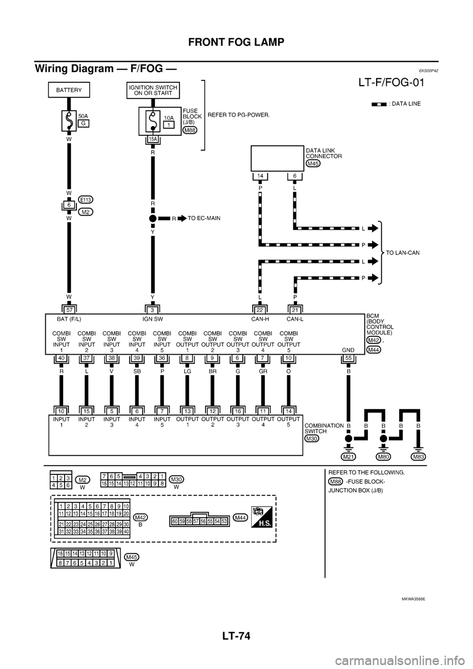
The front fog lamp switch is built into the combination switch. The lighting switch must be in the 1ST position,
2ND position or AUTO position (LOW beam is ON) and the front fog lamp switch must be ON for front fog lamp
operation.
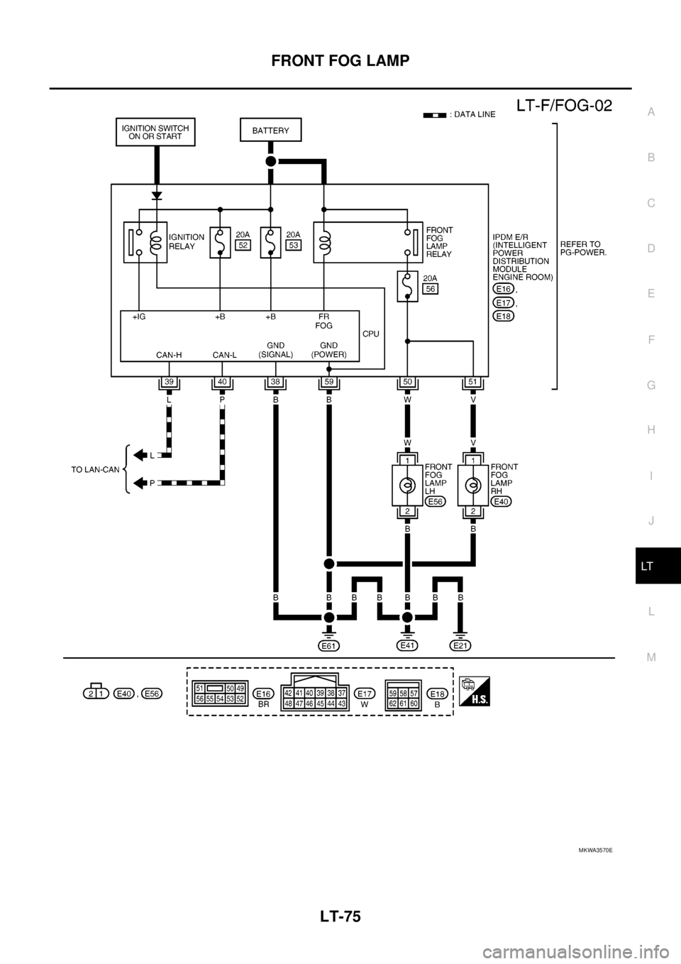
With the front fog lamp switch in the ON position, the CPU of the IPDM E/R grounds the coil side of the front
fog lamp relay. The front fog lamp relay then directs power
lthrough 20A fuse (No. 56, located in IPDM E/R)
lthrough IPDM E/R terminal 50
lto front fog lamp LH terminal 1 and
lthrough IPDM E/R terminal 51
lto front fog lamp RH terminal 1.
Ground is supplied at all times
lto front fog lamp RH and LH terminal 2
lthrough grounds E21, E41 and E61.
With power and ground supplied, the front fog lamps illuminate.
COMBINATION SWITCH READING FUNCTION
Refer toBCS-3, "COMBINATION SWITCH READING FUNCTION".
CAN Communication System DescriptionEKS00P40
Refer toLAN-23, "CAN COMMUNICATION".
Page 2156 of 3171
FRONT FOG LAMP
LT-73
C
D
E
F
G
H
I
J
L
MA
B
LT
SchematicEKS00P41
MKWA3669E
Page 2157 of 3171
LT-74
FRONT FOG LAMP
Wiring Diagram — F/FOG —
EKS00P42
MKWA3569E
Page 2158 of 3171
FRONT FOG LAMP
LT-75
C
D
E
F
G
H
I
J
L
MA
B
LT
MKWA3570E
Page 2159 of 3171
LT-76
FRONT FOG LAMP
MKWA3571E
Page 2160 of 3171
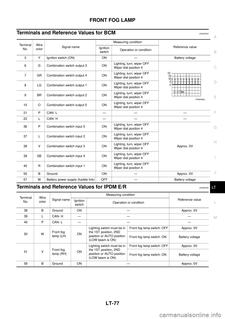
FRONT FOG LAMP
LT-77
C
D
E
F
G
H
I
J
L
MA
B
LT
Terminals and Reference Values for BCMEKS00P43
Terminals and Reference Values for IPDM E/REKS00P44
Te r m i n a l
No.Wire
colorSignal nameMeasuring condition
Reference value
Ignition
switchOperation or condition
3 Y Ignition switch (ON) ON — Battery voltage
6 G Combination switch output 3 ONLighting, turn, wiper OFF
Wiper dial position 4
7 GR Combination switch output 4 ONLighting, turn, wiper OFF
Wiper dial position 4
8 LG Combination switch output 1 ONLighting, turn, wiper OFF
Wiper dial position 4
9 BR Combination switch output 2 ONLighting, turn, wiper OFF
Wiper dial position 4
10 O Combination switch output 5 ONLighting, turn, wiper OFF
Wiper dial position 4
21 P CAN- L — — —
22 L CAN- H — — —
36 P Combination switch input 5 ONLighting, turn, wiper OFF
Wiper dial position 4
Approx. 0V 37 L Combination switch input 2 ONLighting, turn, wiper OFF
Wiper dial position 4
38 V Combination switch input 3 ONLighting, turn, wiper OFF
Wiper dial position 4
39 SB Combination switch input 4 ONLighting, turn, wiper OFF
Wiper dial position 4
40 R Combination switch input 1 ONLighting, turn, wiper OFF
Wiper dial position 4
55 B Ground ON — Approx. 0V
57 W Battery power supply (fusible link) OFF — Battery voltage
PKIB4958J
Terminal
No.Wire
colorSignal nameMeasuring condition
Reference value
Ignition
switchOperation or condition
38 B Ground ON — Approx. 0V
39 L CAN- H — — —
40 P CAN- L — — —
50 WFront fog
lamp (LH)ONLighting switch must be in
the 1ST position, 2ND
position or AUTO position
(LOW beam is ON)Front fog lamp switch: OFF Approx. 0V
Front fog lamp switch: ON Battery voltage
51 VFront fog
lamp (RH)ONLighting switch must be in
the 1ST position, 2ND
position or AUTO position
(LOW beam is ON)Front fog lamp switch: OFF Approx. 0V
Front fog lamp switch: ON Battery voltage
59 B Ground ON — Approx. 0V
Trending: tire pressure, wheel size, overheating, length, hood release, wheel alignment, Heater Core
