NISSAN NAVARA 2005 Repair Workshop Manual
Manufacturer: NISSAN, Model Year: 2005, Model line: NAVARA, Model: NISSAN NAVARA 2005Pages: 3171, PDF Size: 49.59 MB
Page 2191 of 3171
LT-108
TURN SIGNAL AND HAZARD WARNING LAMPS
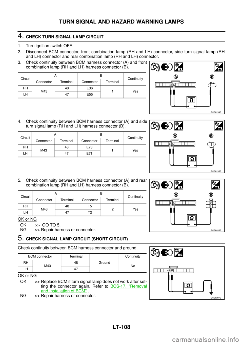
4.CHECK TURN SIGNAL LAMP CIRCUIT
1. Turn ignition switch OFF.
2. Disconnect BCM connector, front combination lamp (RH and LH) connector, side turn signal lamp (RH
and LH) connector and rear combination lamp (RH and LH) connector.
3. Check continuity between BCM harness connector (A) and front
combination lamp (RH and LH) harness connector (B).
4. Check continuity between BCM harness connector (A) and side
turn signal lamp (RH and LH) harness connector (B).
5. Check continuity between BCM harness connector (A) and rear
combination lamp (RH and LH) harness connector (B).
OK or NG
OK >> GO TO 5.
NG >> Repair harness or connector.
5.CHECK SIGNAL LAMP CIRCUIT (SHORT CIRCUIT)
Check continuity between BCM harness connector and ground.
OK or NG
OK >> Replace BCM if turn signal lamp does not work after set-
ting the connector again. Refer toBCS-17, "
Removal
and Installation of BCM".
NG >> Repair harness or connector.
CircuitAB
Continuity
Connector Terminal Connector Terminal
RH
M4348 E36
1Yes
LH 47 E55
SKIB6294E
CircuitAB
Continuity
Connector Terminal Connector Terminal
RH
M4348 E73
1Yes
LH 47 E71
SKIB6295E
CircuitAB
Continuity
Connector Terminal Connector Terminal
RH
M4348 T5
2Yes
LH 47 T2
SKIB6836E
BCM connector Terminal
GroundContinuity
RH
M4348
No
LH 47
SKIB6297E
Page 2192 of 3171
TURN SIGNAL AND HAZARD WARNING LAMPS
LT-109
C
D
E
F
G
H
I
J
L
MA
B
LT
Hazard Warning Lamp Does Not Operate But Turn Signal Lamps OperateEKS00P8E
1.CHECK BULB
Make sure bulb standard of each turn signal lamp is correct.
OK or NG
OK >> GO TO 2.
NG >> Replace turn signal lamp bulb.
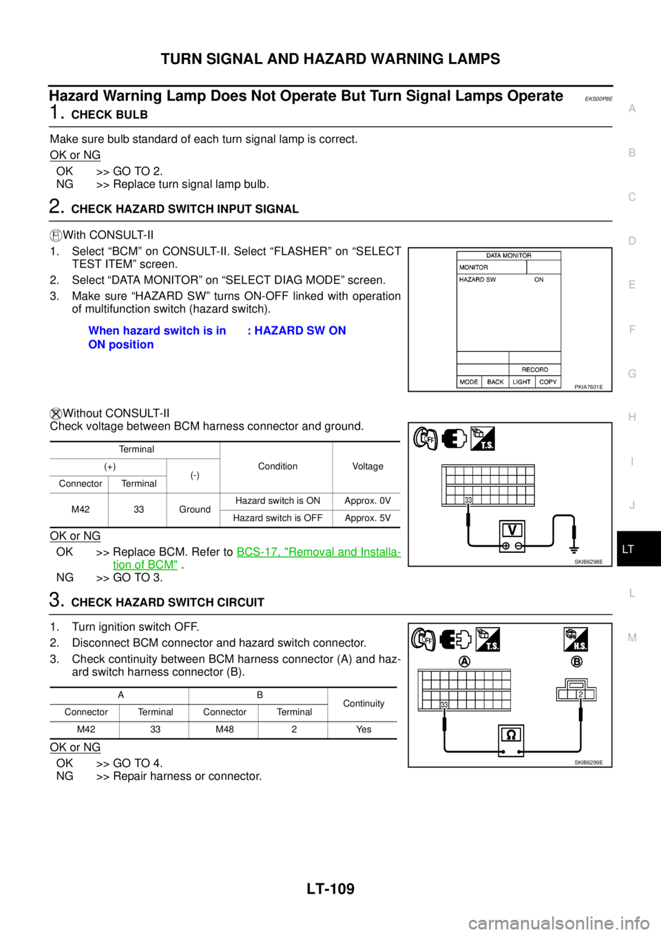
2.CHECK HAZARD SWITCH INPUT SIGNAL
With CONSULT-II
1. Select “BCM” on CONSULT-II. Select “FLASHER” on “SELECT
TEST ITEM” screen.
2. Select “DATA MONITOR” on “SELECT DIAG MODE” screen.
3. Make sure “HAZARD SW” turns ON-OFF linked with operation
of multifunction switch (hazard switch).
Without CONSULT-II
Check voltage between BCM harness connector and ground.
OK or NG
OK >> Replace BCM. Refer toBCS-17, "Removal and Installa-
tion of BCM".
NG >> GO TO 3.
3.CHECK HAZARD SWITCH CIRCUIT
1. Turn ignition switch OFF.
2. Disconnect BCM connector and hazard switch connector.
3. Check continuity between BCM harness connector (A) and haz-
ard switch harness connector (B).
OK or NG
OK >> GO TO 4.
NG >> Repair harness or connector.When hazard switch is in
ON position: HAZARD SW ON
PKIA7601E
Terminal
Condition Voltage (+)
(-)
Connector Terminal
M42 33 GroundHazard switch is ON Approx. 0V
Hazard switch is OFF Approx. 5V
SKIB6298E
AB
Continuity
Connector Terminal Connector Terminal
M4233M48 2 Yes
SKIB6299E
Page 2193 of 3171
LT-110
TURN SIGNAL AND HAZARD WARNING LAMPS
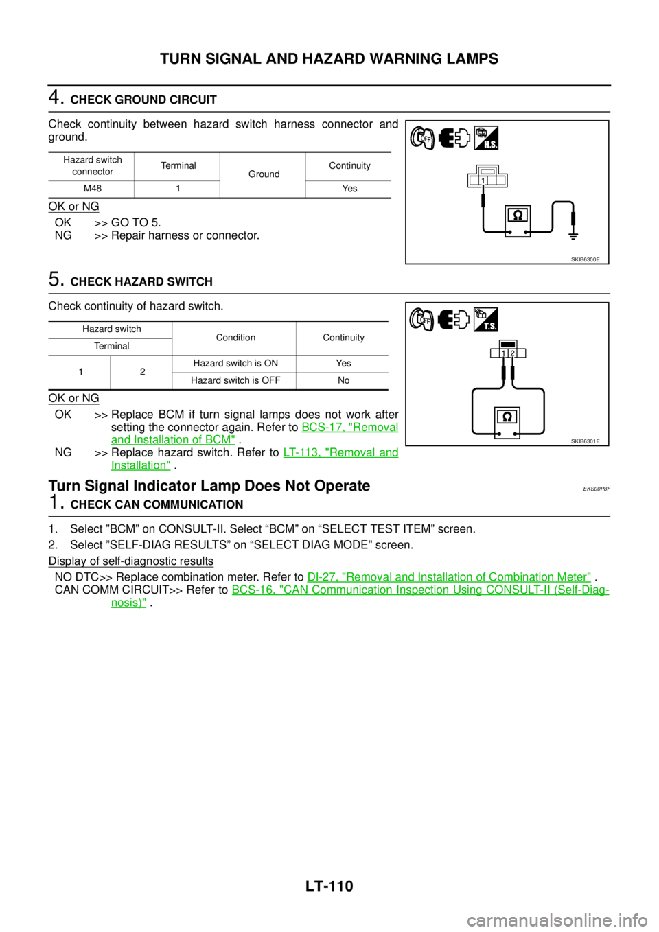
4.CHECK GROUND CIRCUIT
Check continuity between hazard switch harness connector and
ground.
OK or NG
OK >> GO TO 5.
NG >> Repair harness or connector.
5.CHECK HAZARD SWITCH
Check continuity of hazard switch.
OK or NG
OK >> Replace BCM if turn signal lamps does not work after
setting the connector again. Refer toBCS-17, "
Removal
and Installation of BCM".
NG >> Replace hazard switch. Refer toLT- 11 3 , "
Removal and
Installation".
Turn Signal Indicator Lamp Does Not OperateEKS00P8F
1.CHECK CAN COMMUNICATION
1. Select ”BCM” on CONSULT-II. Select “BCM” on “SELECT TEST ITEM” screen.
2. Select ”SELF-DIAG RESULTS” on “SELECT DIAG MODE” screen.
Display of self
-diagnostic results
NO DTC>> Replace combination meter. Refer toDI-27, "Removal and Installation of Combination Meter".
CAN COMM CIRCUIT>> Refer toBCS-16, "
CAN Communication Inspection Using CONSULT-II (Self-Diag-
nosis)".
Hazard switch
connectorTerminal
GroundContinuity
M48 1 Yes
SKIB6300E
Hazard switch
Condition Continuity
Terminal
12Hazard switch is ON Yes
Hazard switch is OFF No
SKIB6301E
Page 2194 of 3171
TURN SIGNAL AND HAZARD WARNING LAMPS
LT-111
C
D
E
F
G
H
I
J
L
MA
B
LT
Bulb Replacement (Front Turn Signal Lamp)EKS00P8G
Refer toLT-29, "Bulb Replacement".
Bulb Replacement (Rear Turn Signal Lamp)EKS00P8H
Refer toLT- 1 4 3 , "Bulb Replacement".
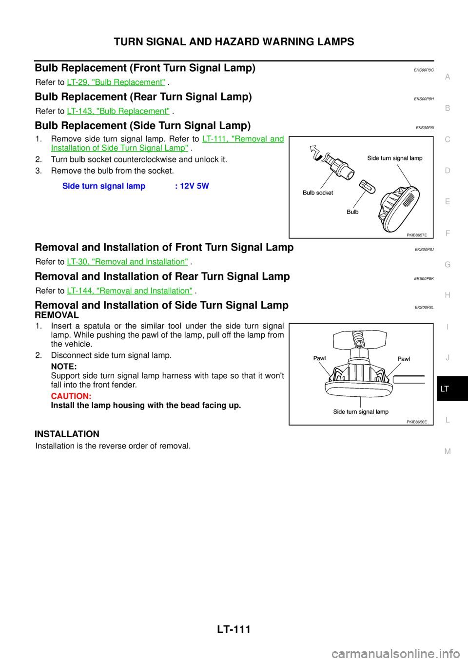
Bulb Replacement (Side Turn Signal Lamp)EKS00P8I
1. Remove side turn signal lamp. Refer toLT- 111 , "Removal and
Installation of Side Turn Signal Lamp".
2. Turn bulb socket counterclockwise and unlock it.
3. Remove the bulb from the socket.
Removal and Installation of Front Turn Signal LampEKS00P8J
Refer toLT-30, "Removal and Installation".
Removal and Installation of Rear Turn Signal LampEKS00P8K
Refer toLT- 1 4 4 , "Removal and Installation".
Removal and Installation of Side Turn Signal LampEKS00P8L
REMOVAL
1. Insert a spatula or the similar tool under the side turn signal
lamp. While pushing the pawl of the lamp, pull off the lamp from
the vehicle.
2. Disconnect side turn signal lamp.
NOTE:
Support side turn signal lamp harness with tape so that it won't
fall into the front fender.
CAUTION:
Install the lamp housing with the bead facing up.
INSTALLATION
Installation is the reverse order of removal.Side turn signal lamp : 12V 5W
PKIB8657E
PKIB8656E
Page 2195 of 3171
LT-112
LIGHTING AND TURN SIGNAL SWITCH
LIGHTING AND TURN SIGNAL SWITCH
PFP:25540
Removal and InstallationEKS00P8N
REMOVAL
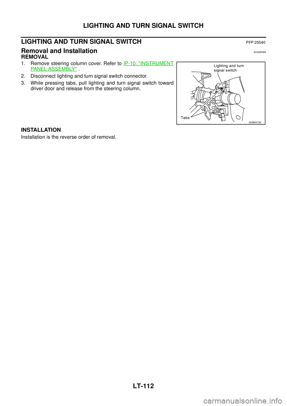
1. Remove steering column cover. Refer toIP-10, "INSTRUMENT
PANEL ASSEMBLY".
2. Disconnect lighting and turn signal switch connector.
3. While pressing tabs, pull lighting and turn signal switch toward
driver door and release from the steering column.
INSTALLATION
Installation is the reverse order of removal.
SKIB6473E
Page 2196 of 3171
HAZARD SWITCH
LT-113
C
D
E
F
G
H
I
J
L
MA
B
LT
HAZARD SWITCHPFP:25290
Removal and InstallationEKS00P8O
REMOVAL
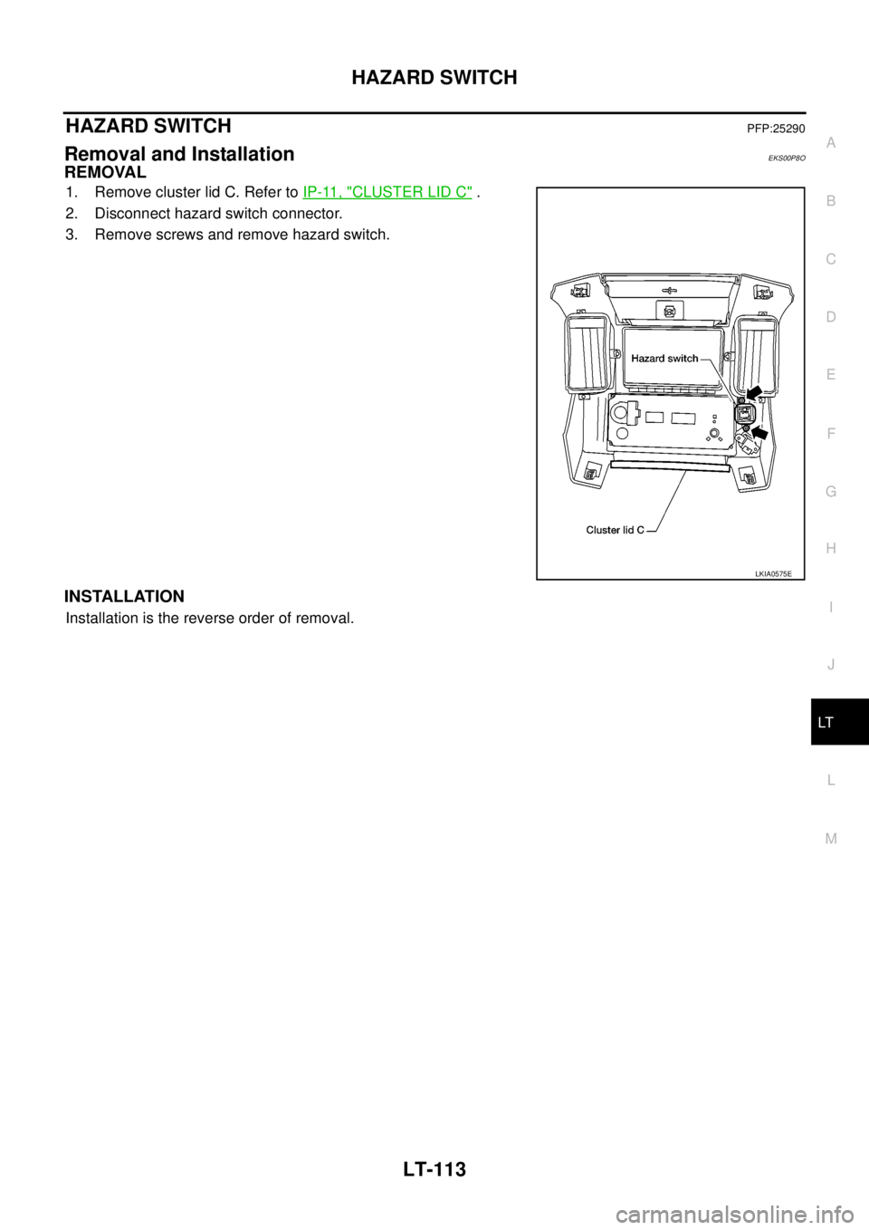
1. Remove cluster lid C. Refer toIP-11, "CLUSTER LID C".
2. Disconnect hazard switch connector.
3. Remove screws and remove hazard switch.
INSTALLATION
Installation is the reverse order of removal.
LKIA0575E
Page 2197 of 3171
LT-114
COMBINATION SWITCH
COMBINATION SWITCH
PFP:25567
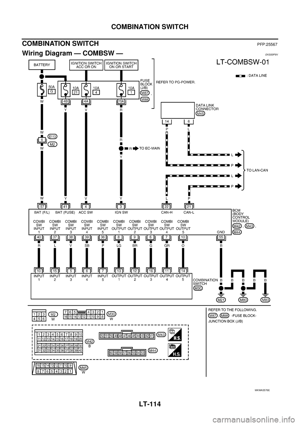
Wiring Diagram — COMBSW —EKS00P9V
MKWA3576E
Page 2198 of 3171
COMBINATION SWITCH
LT-115
C
D
E
F
G
H
I
J
L
MA
B
LT
Combination Switch Reading FunctionEKS00P9W
Refer toBCS-3, "COMBINATION SWITCH READING FUNCTION".
CONSULT-II Function (BCM)EKS00P9X
CONSULT-II can display each diagnostic item using the diagnostic test mode shown following.
CONSULT-II OPERATION
CAUTION:
If CONSULT-II is used with no connection of CONSULT-II CONVERTER, malfunctions might be
detected in self-diagnosis depending on control unit which carries out CAN communication.
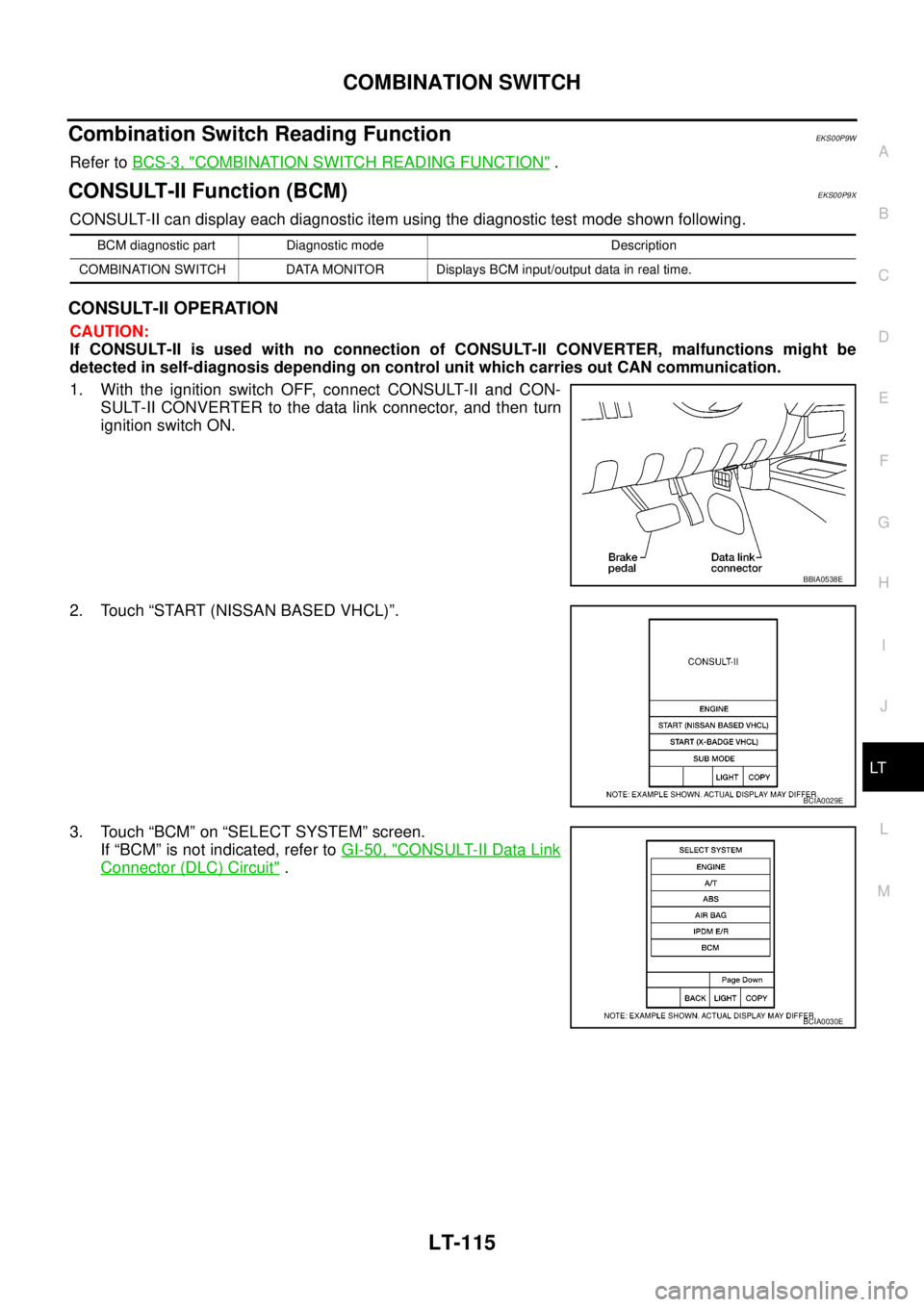
1. With the ignition switch OFF, connect CONSULT-II and CON-
SULT-II CONVERTER to the data link connector, and then turn
ignition switch ON.
2. Touch “START (NISSAN BASED VHCL)”.
3. Touch “BCM” on “SELECT SYSTEM” screen.
If “BCM” is not indicated, refer toGI-50, "
CONSULT-II Data Link
Connector (DLC) Circuit".
BCM diagnostic part Diagnostic mode Description
COMBINATION SWITCH DATA MONITOR Displays BCM input/output data in real time.
BBIA0538E
BCIA0029E
BCIA0030E
Page 2199 of 3171
LT-116
COMBINATION SWITCH
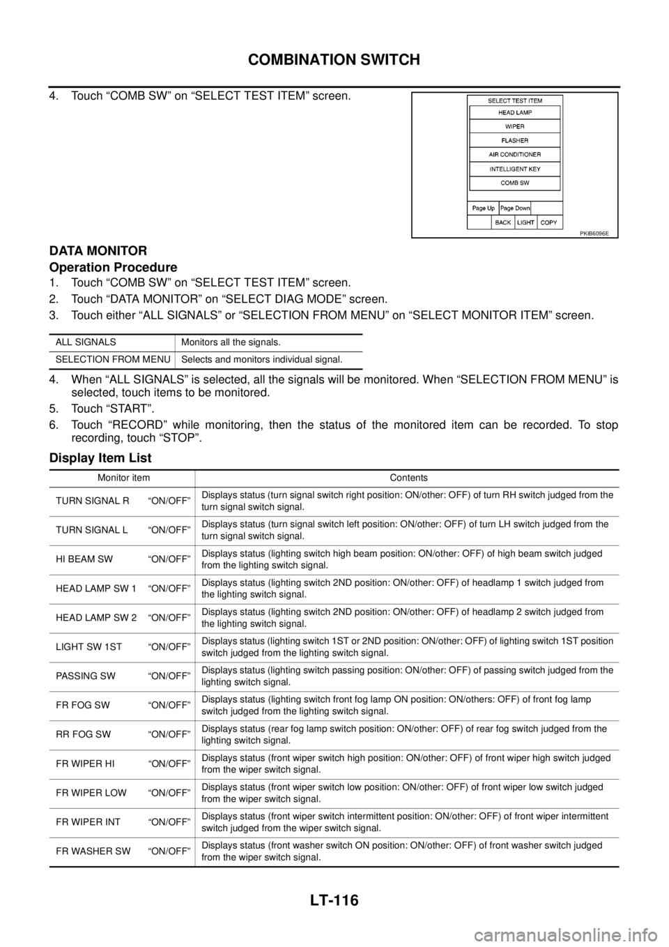
4. Touch “COMB SW” on “SELECT TEST ITEM” screen.
DATA MONITOR
Operation Procedure
1. Touch “COMB SW” on “SELECT TEST ITEM” screen.
2. Touch “DATA MONITOR” on “SELECT DIAG MODE” screen.
3. Touch either “ALL SIGNALS” or “SELECTION FROM MENU” on “SELECT MONITOR ITEM” screen.
4. When “ALL SIGNALS” is selected, all the signals will be monitored. When “SELECTION FROM MENU” is
selected, touch items to be monitored.
5. Touch “START”.
6. Touch “RECORD” while monitoring, then the status of the monitored item can be recorded. To stop
recording, touch “STOP”.
Display Item List
PKIB6096E
ALL SIGNALS Monitors all the signals.
SELECTION FROM MENU Selects and monitors individual signal.
Monitor item Contents
TURN SIGNAL R “ON/OFF”Displays status (turn signal switch right position: ON/other: OFF) of turn RH switch judged from the
turn signal switch signal.
TURN SIGNAL L “ON/OFF”Displays status (turn signal switch left position: ON/other: OFF) of turn LH switch judged from the
turn signal switch signal.
HI BEAM SW “ON/OFF”Displays status (lighting switch high beam position: ON/other: OFF) of high beam switch judged
from the lighting switch signal.
HEAD LAMP SW 1 “ON/OFF”Displays status (lighting switch 2ND position: ON/other: OFF) of headlamp 1 switch judged from
the lighting switch signal.
HEAD LAMP SW 2 “ON/OFF”Displays status (lighting switch 2ND position: ON/other: OFF) of headlamp 2 switch judged from
the lighting switch signal.
LIGHT SW 1ST “ON/OFF”Displays status (lighting switch 1ST or 2ND position: ON/other: OFF) of lighting switch 1ST position
switch judged from the lighting switch signal.
PASSING SW “ON/OFF”Displays status (lighting switch passing position: ON/other: OFF) of passing switch judged from the
lighting switch signal.
FR FOG SW “ON/OFF”Displays status (lighting switch front fog lamp ON position: ON/others: OFF) of front fog lamp
switch judged from the lighting switch signal.
RR FOG SW “ON/OFF”Displays status (rear fog lamp switch position: ON/other: OFF) of rear fog switch judged from the
lighting switch signal.
FR WIPER HI “ON/OFF”Displays status (front wiper switch high position: ON/other: OFF) of front wiper high switch judged
from the wiper switch signal.
FR WIPER LOW “ON/OFF”Displays status (front wiper switch low position: ON/other: OFF) of front wiper low switch judged
from the wiper switch signal.
FR WIPER INT “ON/OFF”Displays status (front wiper switch intermittent position: ON/other: OFF) of front wiper intermittent
switch judged from the wiper switch signal.
FR WASHER SW “ON/OFF”Displays status (front washer switch ON position: ON/other: OFF) of front washer switch judged
from the wiper switch signal.
Page 2200 of 3171

COMBINATION SWITCH
LT-117
C
D
E
F
G
H
I
J
L
MA
B
LT
INT VOLUME “1 - 7”Displays status (wiper intermittent dial position setting 1-7) of intermittent volume switch judged
from the wiper switch signal.
RR WIPER ON “ON/OFF”Displays status (rear wiper switch ON position: ON/other: OFF) of rear wiper switch judged from the
wiper switch signal.
RR WIPER INT “ON/OFF”Displays status (rear wiper switch intermittent position: ON/other: OFF) of rear wiper intermittent
switch judged from the wiper switch signal.
RR WASHER SW “ON/OFF”Displays status (rear washer switch ON position: ON/other: OFF) of rear washer switch judged
from the wiper switch signal. Monitor item Contents