NISSAN NAVARA 2005 Repair Workshop Manual
Manufacturer: NISSAN, Model Year: 2005, Model line: NAVARA, Model: NISSAN NAVARA 2005Pages: 3171, PDF Size: 49.59 MB
Page 2691 of 3171
RF-14
SUNROOF
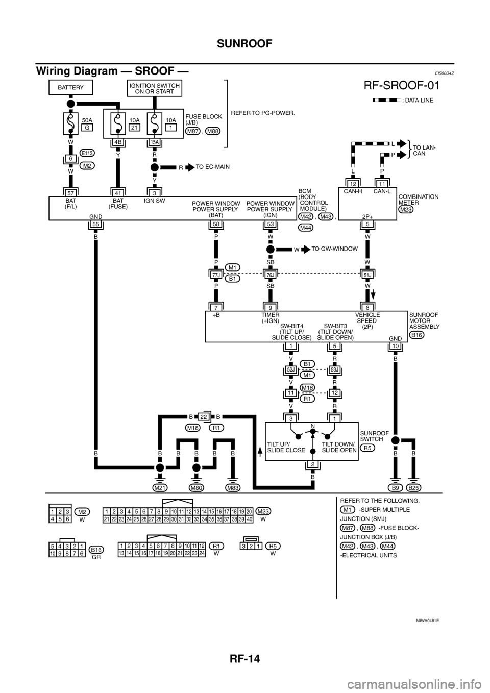
Wiring Diagram — SROOF —
EIS00D4Z
MIWA0481E
Page 2692 of 3171
SUNROOF
RF-15
C
D
E
F
G
H
J
K
L
MA
B
RF
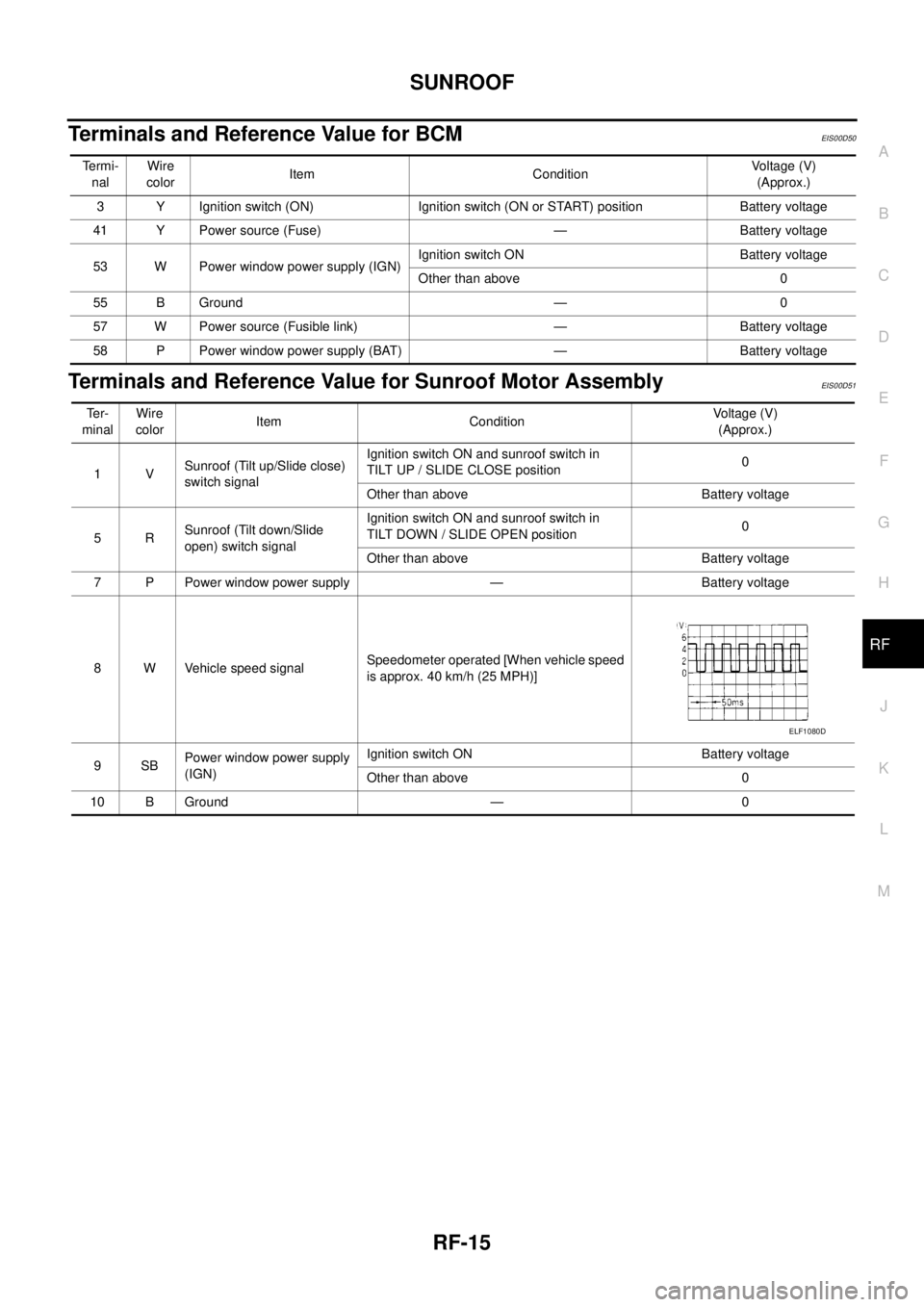
Terminals and Reference Value for BCMEIS00D50
Terminals and Reference Value for Sunroof Motor AssemblyEIS00D51
Te r m i -
nalWire
colorItem ConditionVo l ta g e (V )
(Approx.)
3 Y Ignition switch (ON) Ignition switch (ON or START) position Battery voltage
41 Y Power source (Fuse) — Battery voltage
53 W Power window power supply (IGN)Ignition switch ON Battery voltage
Other than above 0
55 B Ground — 0
57 W Power source (Fusible link) — Battery voltage
58 P Power window power supply (BAT) — Battery voltage
Te r -
minalWire
colorItem ConditionVoltage (V)
(Approx.)
1VSunroof (Tilt up/Slide close)
switch signalIgnition switch ON and sunroof switch in
TILT UP / SLIDE CLOSE position0
Other than above Battery voltage
5RSunroof (Tilt down/Slide
open) switch signalIgnition switch ON and sunroof switch in
TILT DOWN / SLIDE OPEN position0
Other than above Battery voltage
7 P Power window power supply — Battery voltage
8 W Vehicle speed signalSpeedometer operated [When vehicle speed
is approx. 40 km/h (25 MPH)]
9SBPower window power supply
(IGN)Ignition switch ON Battery voltage
Other than above 0
10 B Ground — 0
ELF1080D
Page 2693 of 3171
RF-16
SUNROOF
Work Flow
EIS00D52
1. Check the symptom and customer's requests.
2. Understand the outline of system. Refer toRF-11, "
System Description".
3. According to the trouble diagnosis chart, repair or replace the cause of the malfunction. Refer toRF-16,
"Trouble Diagnosis Symptom Chart".
4. Does sunroof system operate normally? If Yes, GO TO 5. If No, GO TO 3.
5. INSPECTION END.
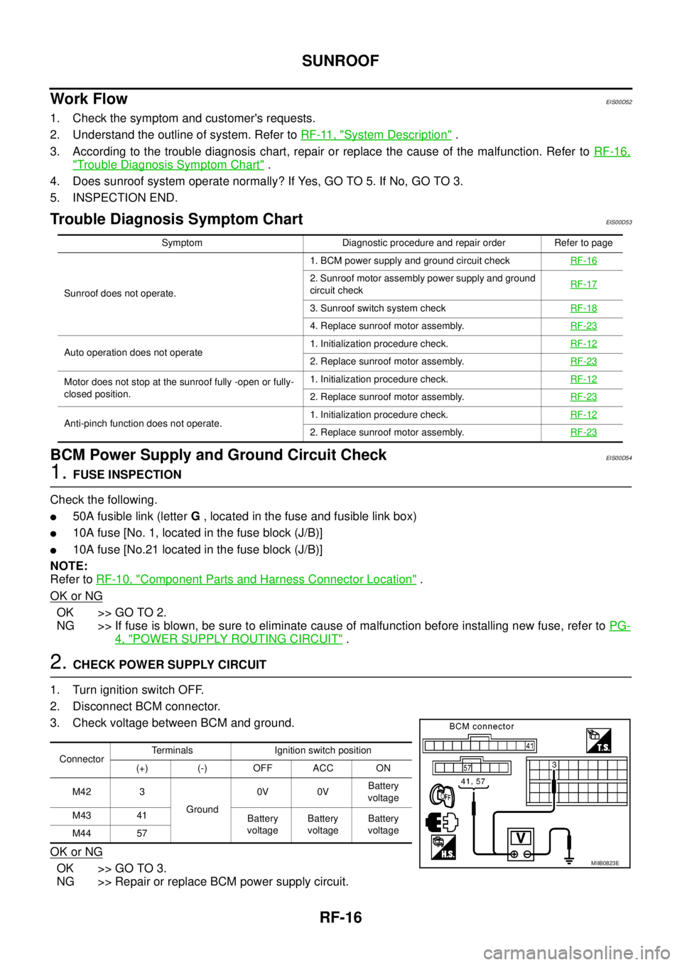
Trouble Diagnosis Symptom ChartEIS00D53
BCM Power Supply and Ground Circuit CheckEIS00D54
1.FUSE INSPECTION
Check the following.
l50A fusible link (letterG, located in the fuse and fusible link box)
l10A fuse [No. 1, located in the fuse block (J/B)]
l10A fuse [No.21 located in the fuse block (J/B)]
NOTE:
Refer toRF-10, "
Component Parts and Harness Connector Location".
OK or NG
OK >> GO TO 2.
NG >> If fuse is blown, be sure to eliminate cause of malfunction before installing new fuse, refer toPG-
4, "POWER SUPPLY ROUTING CIRCUIT".
2.CHECK POWER SUPPLY CIRCUIT
1. Turn ignition switch OFF.
2. Disconnect BCM connector.
3. Check voltage between BCM and ground.
OK or NG
OK >> GO TO 3.
NG >> Repair or replace BCM power supply circuit.
Symptom Diagnostic procedure and repair order Refer to page
Sunroof does not operate.1. BCM power supply and ground circuit checkRF-16
2. Sunroof motor assembly power supply and ground
circuit checkRF-17
3. Sunroof switch system checkRF-18
4. Replace sunroof motor assembly.RF-23
Auto operation does not operate1. Initialization procedure check.RF-122. Replace sunroof motor assembly.RF-23
Motor does not stop at the sunroof fully -open or fully-
closed position.1. Initialization procedure check.RF-12
2. Replace sunroof motor assembly.RF-23
Anti-pinch function does not operate.1. Initialization procedure check.RF-122. Replace sunroof motor assembly.RF-23
ConnectorTerminals Ignition switch position
(+) (-) OFF ACC ON
M42 3
Ground0V 0VBattery
voltage
M43 41
Battery
voltageBattery
voltageBattery
voltage
M44 57
MIIB0823E
Page 2694 of 3171
SUNROOF
RF-17
C
D
E
F
G
H
J
K
L
MA
B
RF
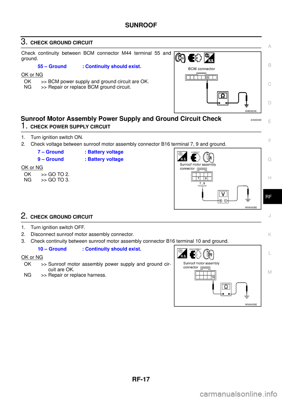
3.CHECK GROUND CIRCUIT
Check continuity between BCM connector M44 terminal 55 and
ground.
OK or NG
OK >> BCM power supply and ground circuit are OK.
NG >> Repair or replace BCM ground circuit.
Sunroof Motor Assembly Power Supply and Ground Circuit CheckEIS00D55
1.CHECK POWER SUPPLY CIRCUIT
1. Turn ignition switch ON.
2. Check voltage between sunroof motor assembly connector B16 terminal 7, 9 and ground.
OK or NG
OK >> GO TO 2.
NG >> GO TO 3.
2.CHECK GROUND CIRCUIT
1. Turn ignition switch OFF.
2. Disconnect sunroof motor assembly connector.
3. Check continuity between sunroof motor assembly connector B16 terminal 10 and ground.
OK or NG
OK >> Sunroof motor assembly power supply and ground cir-
cuit are OK.
NG >> Repair or replace harness.55 – Ground : Continuity should exist.
MIIB0824E
7 – Ground : Battery voltage
9 – Ground : Battery voltage
WIIA0438E
10 – Ground : Continuity should exist.
WIIA0439E
Page 2695 of 3171
RF-18
SUNROOF
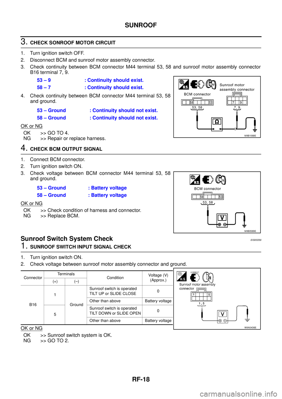
3.CHECK SONROOF MOTOR CIRCUIT
1. Turn ignition switch OFF.
2. Disconnect BCM and sunroof motor assembly connector.
3. Check continuity between BCM connector M44 terminal 53, 58 and sunroof motor assembly connector
B16 terminal 7, 9.
4. Check continuity between BCM connector M44 terminal 53, 58
and ground.
OK or NG
OK >> GO TO 4.
NG >> Repair or replace harness.
4.CHECK BCM OUTPUT SIGNAL
1. Connect BCM connector.
2. Turn ignition switch ON.
3. Check voltage between BCM connector M44 terminal 53, 58
and ground.
OK or NG
OK >> Check condition of harness and connector.
NG >> Replace BCM.
Sunroof Switch System CheckEIS00D56
1.SUNROOF SWITCH INPUT SIGNAL CHECK
1. Turn ignition switch ON.
2. Check voltage between sunroof motor assembly connector and ground.
OK or NG
OK >> Sunroof switch system is OK.
NG >> GO TO 2.53 – 9 : Continuity should exist.
58 – 7 : Continuity should exist.
53 – Ground : Continuity should not exist.
58 – Ground : Continuity should not exist.
MIIB1068E
53 – Ground : Battery voltage
58 – Ground : Battery voltage
MIIB0589E
ConnectorTerminals
ConditionVoltag e (V)
(Approx.)
(+) (–)
B161
GroundSunroof switch is operated
TILT UP or SLIDE CLOSE0
Other than above Battery voltage
5Sunroof switch is operated
TILT DOWN or SLIDE OPEN0
Other than above Battery voltage
WIIA0436E
Page 2696 of 3171
SUNROOF
RF-19
C
D
E
F
G
H
J
K
L
MA
B
RF
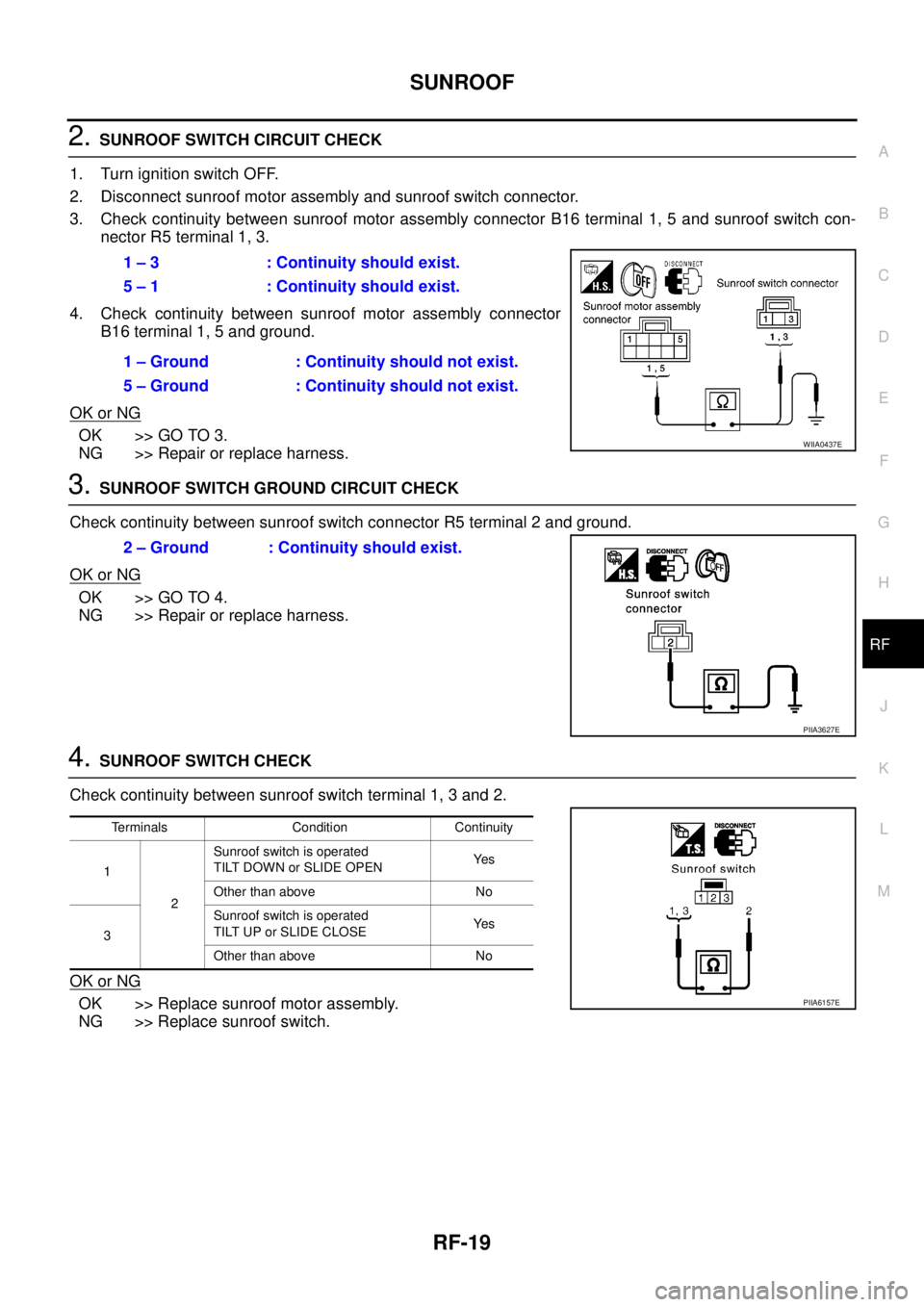
2.SUNROOF SWITCH CIRCUIT CHECK
1. Turn ignition switch OFF.
2. Disconnect sunroof motor assembly and sunroof switch connector.
3. Check continuity between sunroof motor assembly connector B16 terminal 1, 5 and sunroof switch con-
nector R5 terminal 1, 3.
4. Check continuity between sunroof motor assembly connector
B16 terminal 1, 5 and ground.
OK or NG
OK >> GO TO 3.
NG >> Repair or replace harness.
3.SUNROOF SWITCH GROUND CIRCUIT CHECK
Check continuity between sunroof switch connector R5 terminal 2 and ground.
OK or NG
OK >> GO TO 4.
NG >> Repair or replace harness.
4.SUNROOF SWITCH CHECK
Check continuity between sunroof switch terminal 1, 3 and 2.
OK or NG
OK >> Replace sunroof motor assembly.
NG >> Replace sunroof switch.1 – 3 : Continuity should exist.
5 – 1 : Continuity should exist.
1 – Ground : Continuity should not exist.
5 – Ground : Continuity should not exist.
WIIA0437E
2 – Ground : Continuity should exist.
PIIA3627E
Terminals Condition Continuity
1
2Sunroof switch is operated
TILT DOWN or SLIDE OPENYe s
Other than above No
3Sunroof switch is operated
TILT UP or SLIDE CLOSEYe s
Other than above No
PIIA6157E
Page 2697 of 3171
RF-20
SUNROOF
Fitting Adjustment
EIS00C0M
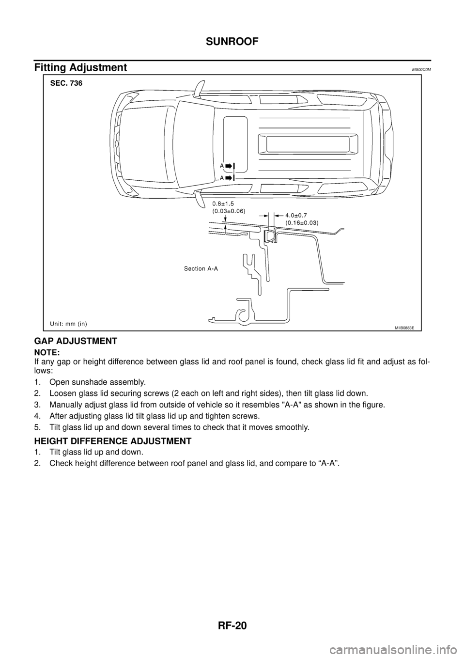
GAP ADJUSTMENT
NOTE:
If any gap or height difference between glass lid and roof panel is found, check glass lid fit and adjust as fol-
lows:
1. Open sunshade assembly.
2. Loosen glass lid securing screws (2 each on left and right sides), then tilt glass lid down.
3. Manually adjust glass lid from outside of vehicle so it resembles "A-A" as shown in the figure.
4. After adjusting glass lid tilt glass lid up and tighten screws.
5. Tilt glass lid up and down several times to check that it moves smoothly.
HEIGHT DIFFERENCE ADJUSTMENT
1. Tilt glass lid up and down.
2. Check height difference between roof panel and glass lid, and compare to “A-A”.
MIIB0883E
Page 2698 of 3171
SUNROOF
RF-21
C
D
E
F
G
H
J
K
L
MA
B
RF
Removal and InstallationEIS00C0N
MIIB0666E
Page 2699 of 3171
RF-22
SUNROOF
lAfter any adjustment, check sunroof operation and glass lid alignment.
lHandle glass lid with care so not to cause damage.
lFor easier installation, mark each point before removal.
CAUTION:
lAlways work with a helper.
lBefore removal, fully close the glass lid assembly. Then, after removal, do not move the motor
assembly.
lAfter installing the sunroof and glass lid, check gap adjustment to ensure there is no malfunction.
SUNROOF UNIT
Removal
CAUTION:
lAlways work with a helper.
lWhen taking sunroof unit out, use shop cloths to protect the seats and trim from damage.
lAfter installing the sunroof unit and glass lid, be sure to check gap adjustment to ensure there is
no malfunction.
1. Remove headlining. Refer toEI-40, "
Removal and Installation".
2. Remove the sunroof glass lid. Refer toRF-22, "
GLASS LID".
3. Disconnect the drain hoses.
4. Remove the mounting nuts from the front end and side rail.
5. Remove the mounting bolts to sunroof bracket and then remove the sunroof unit.
Installation
1. Position the sunroof frame assembly and temporally tighten the mounting bolts to the sunroof brackets.
2. Tighten the mounting nuts to the front end and side rail.
3. Tighten the mounting bolts to sunroof brackets.
4. Connect the drain hoses.
5. Install the sunroof glass lid. Refer toRF-22, "
GLASS LID".
6. Install headlining. Refer toEI-40, "
Removal and Installation".
GLASS LID
Removal
1. Open sunshade.
2. Ensure glass lid is closed.
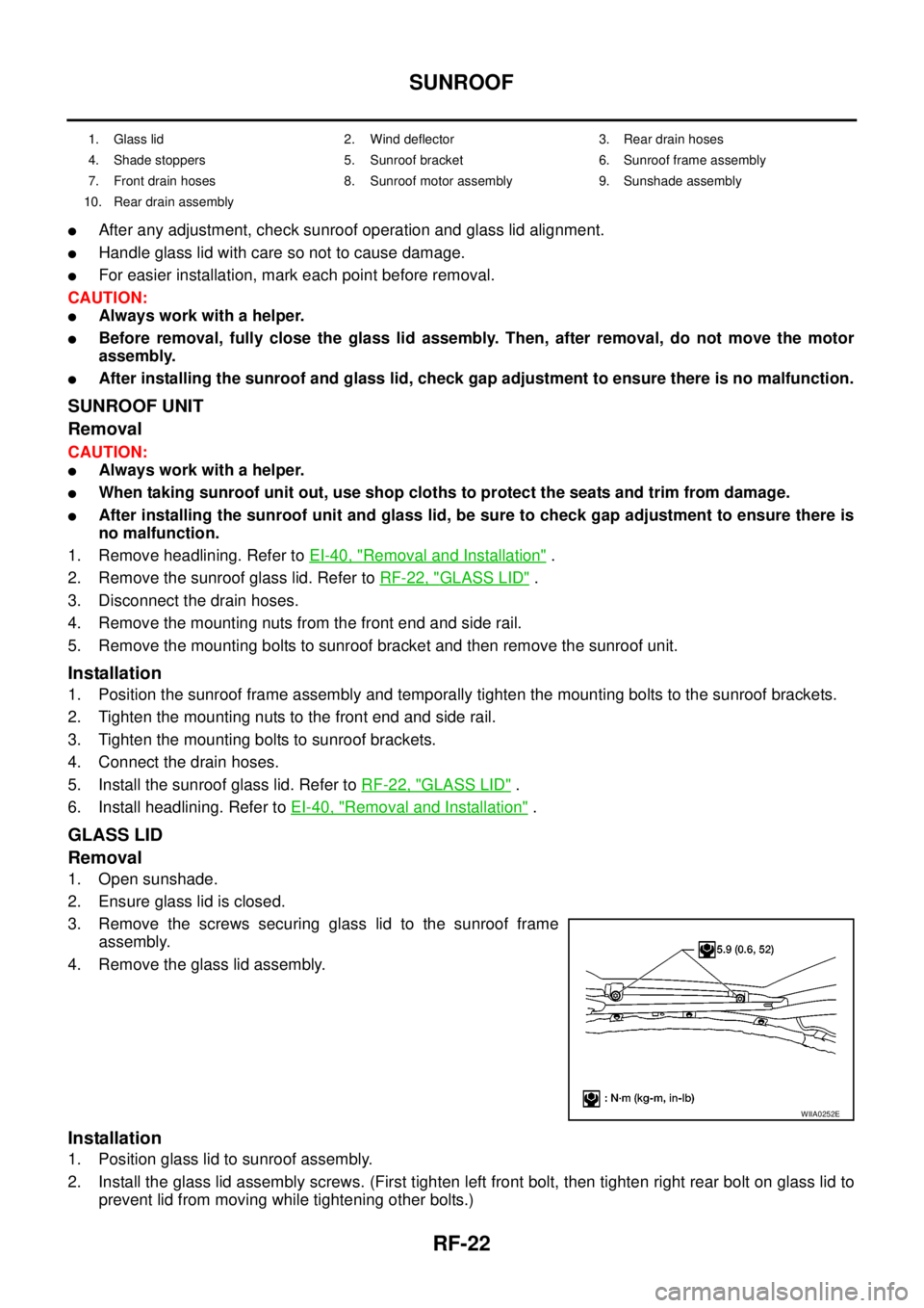
3. Remove the screws securing glass lid to the sunroof frame
assembly.
4. Remove the glass lid assembly.
Installation
1. Position glass lid to sunroof assembly.
2. Install the glass lid assembly screws. (First tighten left front bolt, then tighten right rear bolt on glass lid to
prevent lid from moving while tightening other bolts.)
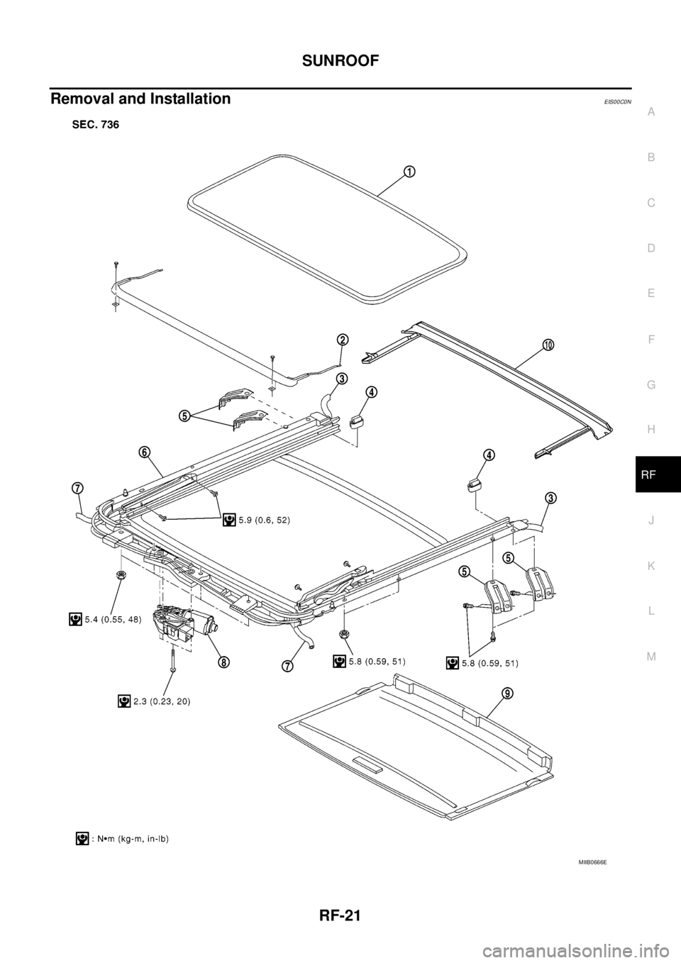
1. Glass lid 2. Wind deflector 3. Rear drain hoses
4. Shade stoppers 5. Sunroof bracket 6. Sunroof frame assembly
7. Front drain hoses 8. Sunroof motor assembly 9. Sunshade assembly
10. Rear drain assembly
WIIA0252E
Page 2700 of 3171
SUNROOF
RF-23
C
D
E
F
G
H
J
K
L
MA
B
RF
3. Adjust the sunroof glass. Refer toRF-20, "Fitting Adjustment".
WIND DEFLECTOR
Removal
NOTE:
Removing is possible even by the on vehicle.
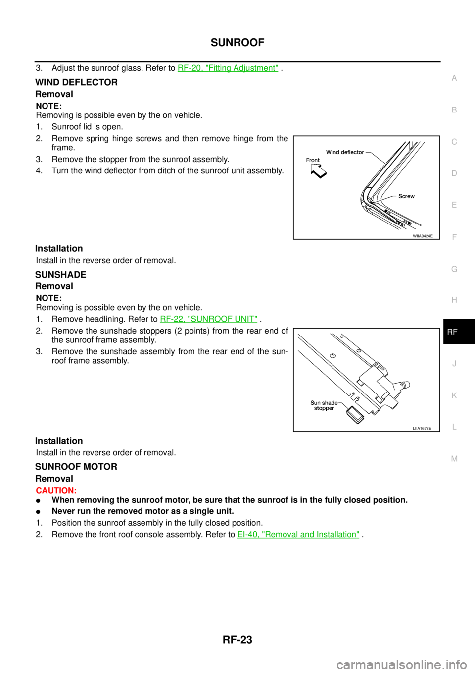
1. Sunroof lid is open.
2. Remove spring hinge screws and then remove hinge from the
frame.
3. Remove the stopper from the sunroof assembly.
4. Turn the wind deflector from ditch of the sunroof unit assembly.
Installation
Install in the reverse order of removal.
SUNSHADE
Removal
NOTE:
Removing is possible even by the on vehicle.
1. Remove headlining. Refer toRF-22, "
SUNROOF UNIT".
2. Remove the sunshade stoppers (2 points) from the rear end of
the sunroof frame assembly.
3. Remove the sunshade assembly from the rear end of the sun-
roof frame assembly.
Installation
Install in the reverse order of removal.
SUNROOF MOTOR
Removal
CAUTION:
lWhen removing the sunroof motor, be sure that the sunroof is in the fully closed position.
lNever run the removed motor as a single unit.
1. Position the sunroof assembly in the fully closed position.
2. Remove the front roof console assembly. Refer toEI-40, "
Removal and Installation".
WIIA0424E
LIIA1672E