NISSAN NAVARA 2005 Repair Workshop Manual
NAVARA 2005
NISSAN
NISSAN
https://www.carmanualsonline.info/img/5/57362/w960_57362-0.png
NISSAN NAVARA 2005 Repair Workshop Manual
Trending: Coolant leak, fuel tank capacity, set clock, coolant reservoir, navigation, climate control, engine
Page 3081 of 3171
TF-114
TRANSFER ASSEMBLY
DISASSEMBLY
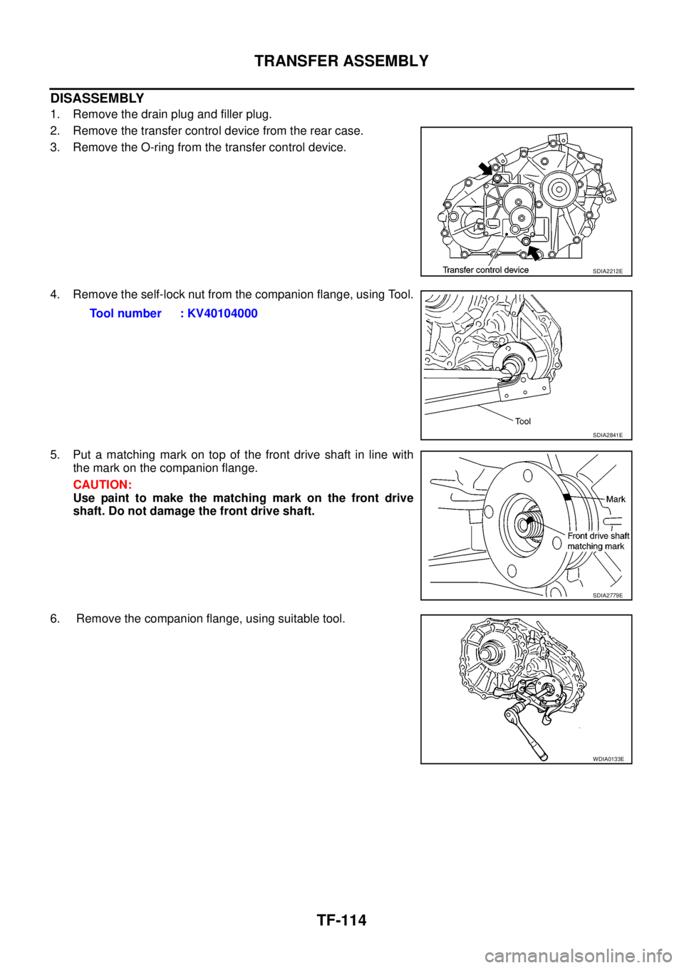
1. Remove the drain plug and filler plug.
2. Remove the transfer control device from the rear case.
3. Remove the O-ring from the transfer control device.
4. Remove the self-lock nut from the companion flange, using Tool.
5. Put a matching mark on top of the front drive shaft in line with
the mark on the companion flange.
CAUTION:
Use paint to make the matching mark on the front drive
shaft. Do not damage the front drive shaft.
6. Remove the companion flange, using suitable tool.
SDIA2212E
Tool number : KV40104000
SDIA2841E
SDIA2779E
WDIA0133E
Page 3082 of 3171
TRANSFER ASSEMBLY
TF-115
C
E
F
G
H
I
J
K
L
MA
B
TF
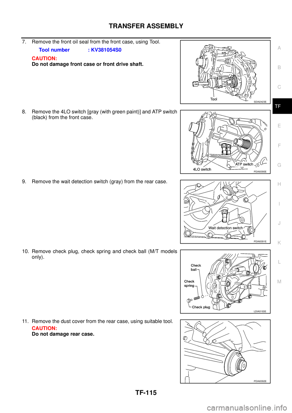
7. Remove the front oil seal from the front case, using Tool.
CAUTION:
Do not damage front case or front drive shaft.
8. Remove the 4LO switch [gray (with green paint)] and ATP switch
(black) from the front case.
9. Remove the wait detection switch (gray) from the rear case.
10. Remove check plug, check spring and check ball (M/T models
only).
11. Remove the dust cover from the rear case, using suitable tool.
CAUTION:
Do not damage rear case.Tool number : KV381054S0
SDIA2423E
PDIA0090E
PDIA0091E
LDIA0193E
PDIA0092E
Page 3083 of 3171
TF-116
TRANSFER ASSEMBLY
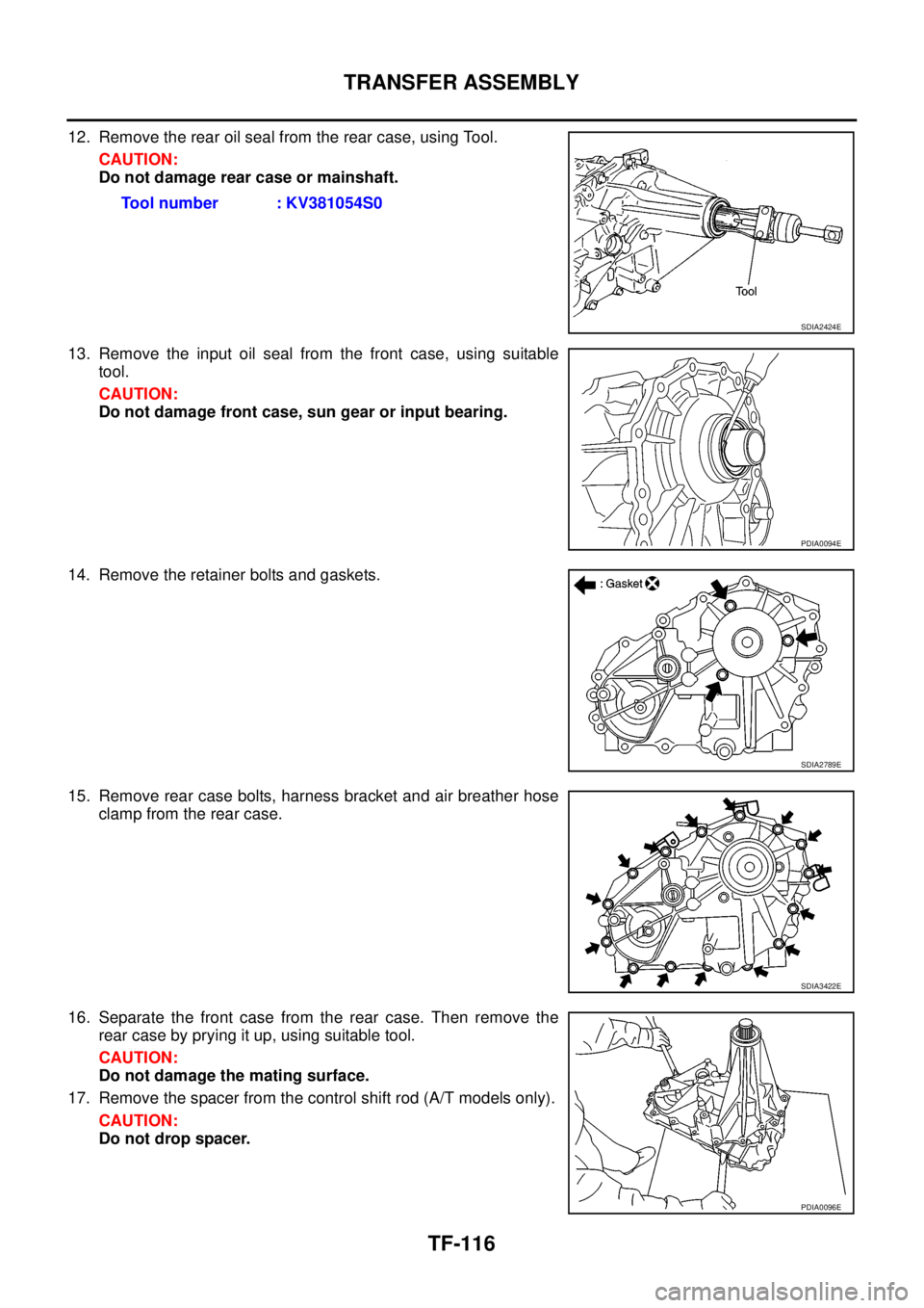
12. Remove the rear oil seal from the rear case, using Tool.
CAUTION:
Do not damage rear case or mainshaft.
13. Remove the input oil seal from the front case, using suitable
tool.
CAUTION:
Do not damage front case, sun gear or input bearing.
14. Remove the retainer bolts and gaskets.
15. Remove rear case bolts, harness bracket and air breather hose
clamp from the rear case.
16. Separate the front case from the rear case. Then remove the
rear case by prying it up, using suitable tool.
CAUTION:
Do not damage the mating surface.
17. Remove the spacer from the control shift rod (A/T models only).
CAUTION:
Do not drop spacer.Tool number : KV381054S0
SDIA2424E
PDIA0094E
SDIA2789E
SDIA3422E
PDIA0096E
Page 3084 of 3171
TRANSFER ASSEMBLY
TF-117
C
E
F
G
H
I
J
K
L
MA
B
TF
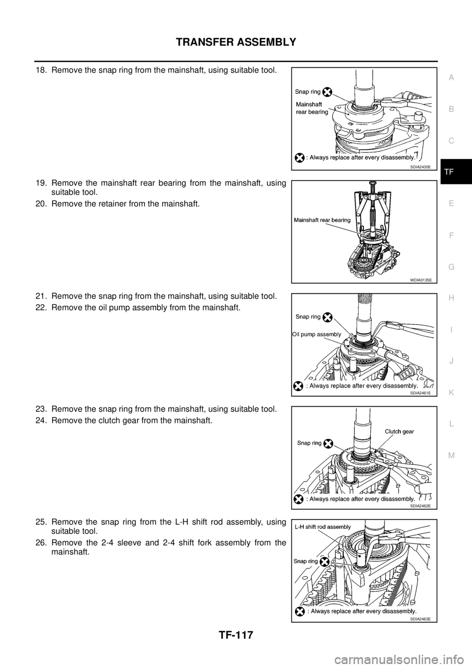
18. Remove the snap ring from the mainshaft, using suitable tool.
19. Remove the mainshaft rear bearing from the mainshaft, using
suitable tool.
20. Remove the retainer from the mainshaft.
21. Remove the snap ring from the mainshaft, using suitable tool.
22. Remove the oil pump assembly from the mainshaft.
23. Remove the snap ring from the mainshaft, using suitable tool.
24. Remove the clutch gear from the mainshaft.
25. Remove the snap ring from the L-H shift rod assembly, using
suitable tool.
26. Remove the 2-4 sleeve and 2-4 shift fork assembly from the
mainshaft.
SDIA2430E
WDIA0135E
SDIA2461E
SDIA2462E
SDIA2463E
Page 3085 of 3171
TF-118
TRANSFER ASSEMBLY
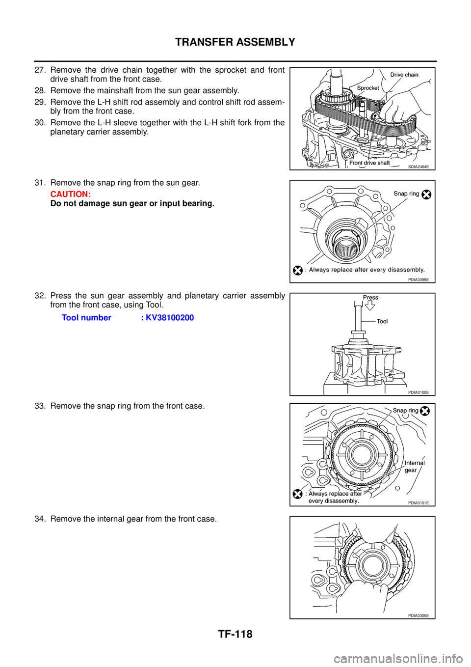
27. Remove the drive chain together with the sprocket and front
drive shaft from the front case.
28. Remove the mainshaft from the sun gear assembly.
29. Remove the L-H shift rod assembly and control shift rod assem-
bly from the front case.
30. Remove the L-H sleeve together with the L-H shift fork from the
planetary carrier assembly.
31. Remove the snap ring from the sun gear.
CAUTION:
Do not damage sun gear or input bearing.
32. Press the sun gear assembly and planetary carrier assembly
from the front case, using Tool.
33. Remove the snap ring from the front case.
34. Remove the internal gear from the front case.
SDIA2464E
PDIA0099E
Tool number : KV38100200
PDIA0100E
PDIA0101E
PDIA0305E
Page 3086 of 3171
TRANSFER ASSEMBLY
TF-119
C
E
F
G
H
I
J
K
L
MA
B
TF
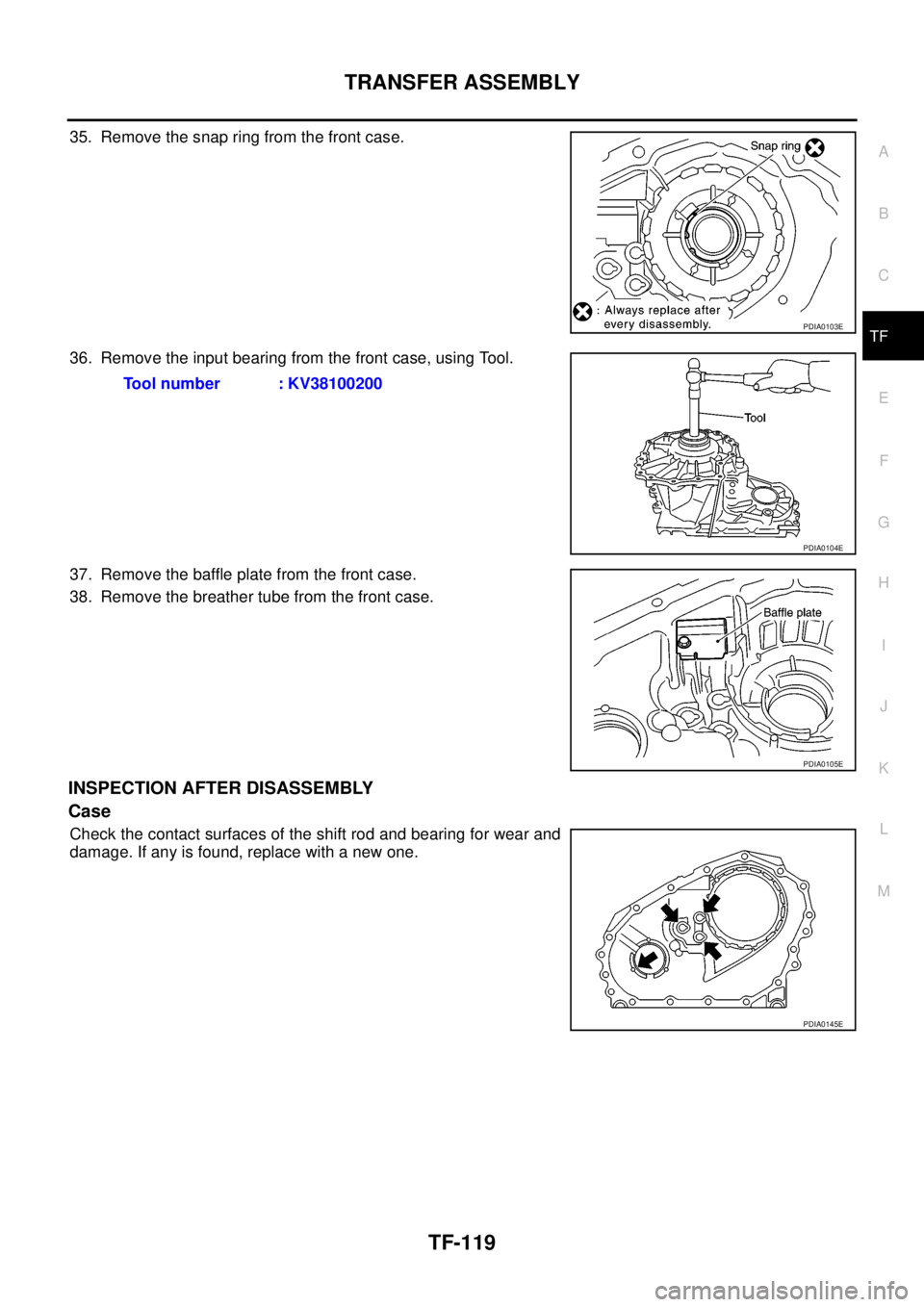
35. Remove the snap ring from the front case.
36. Remove the input bearing from the front case, using Tool.
37. Remove the baffle plate from the front case.
38. Remove the breather tube from the front case.
INSPECTION AFTER DISASSEMBLY
Case
Check the contact surfaces of the shift rod and bearing for wear and
damage. If any is found, replace with a new one.
PDIA0103E
Tool number : KV38100200
PDIA0104E
PDIA0105E
PDIA0145E
Page 3087 of 3171
TF-120
TRANSFER ASSEMBLY
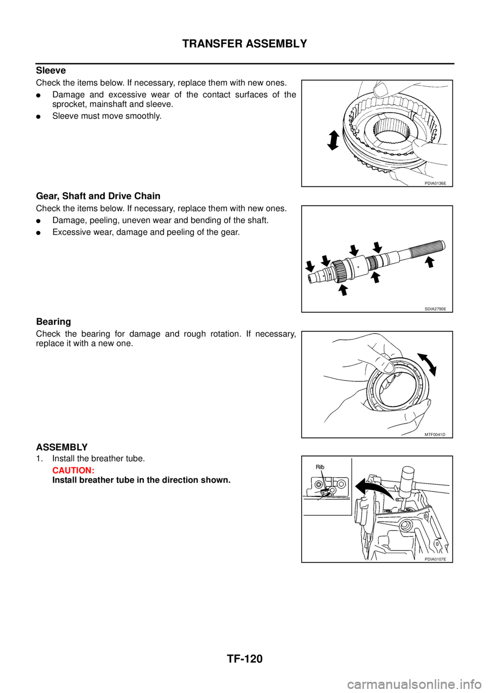
Sleeve
Check the items below. If necessary, replace them with new ones.
lDamage and excessive wear of the contact surfaces of the
sprocket, mainshaft and sleeve.
lSleeve must move smoothly.
Gear, Shaft and Drive Chain
Check the items below. If necessary, replace them with new ones.
lDamage, peeling, uneven wear and bending of the shaft.
lExcessive wear, damage and peeling of the gear.
Bearing
Check the bearing for damage and rough rotation. If necessary,
replace it with a new one.
ASSEMBLY
1. Install the breather tube.
CAUTION:
Install breather tube in the direction shown.
PDIA0136E
SDIA2790E
MTF0041D
PDIA0107E
Page 3088 of 3171
TRANSFER ASSEMBLY
TF-121
C
E
F
G
H
I
J
K
L
MA
B
TF
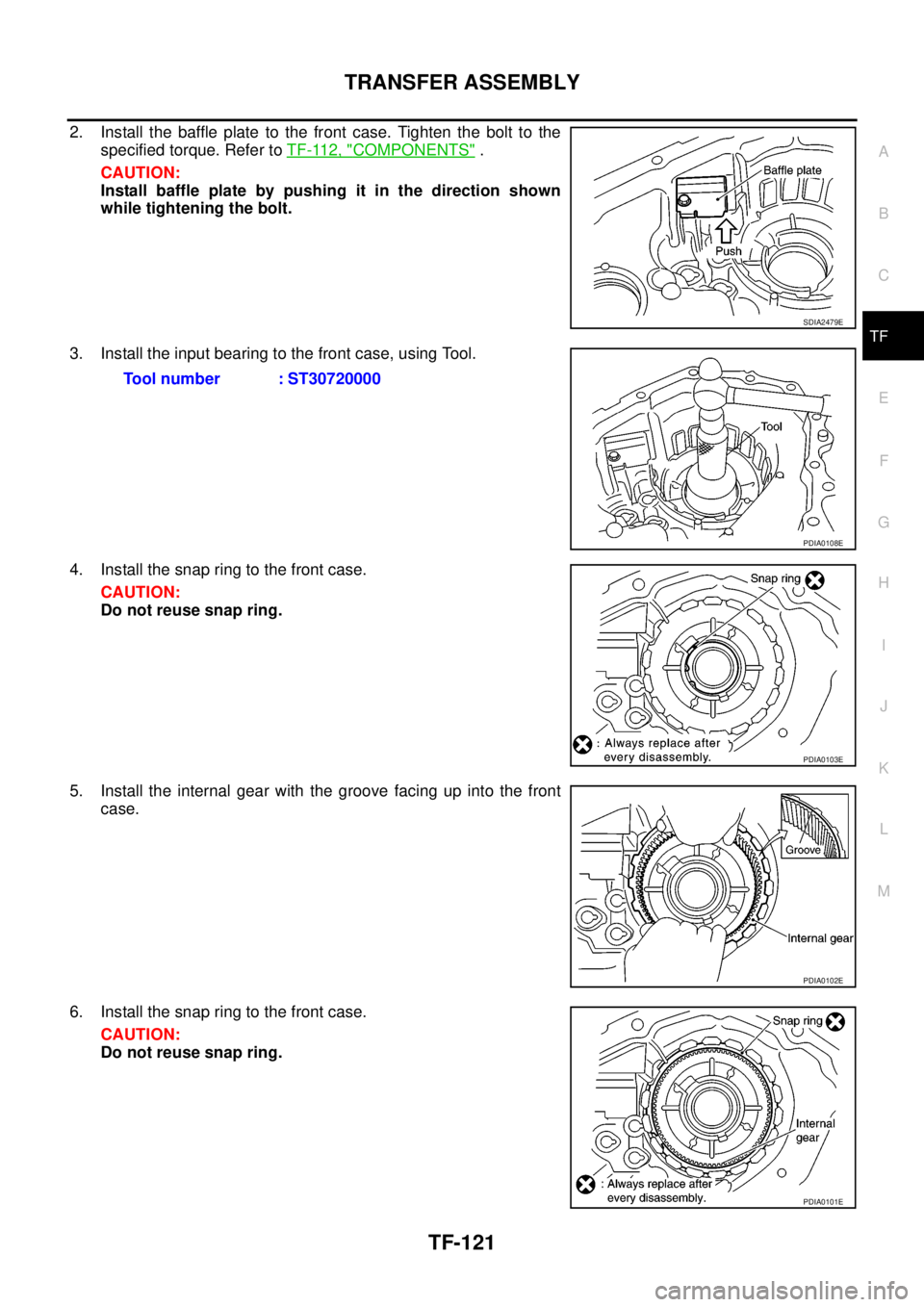
2. Install the baffle plate to the front case. Tighten the bolt to the
specified torque. Refer toTF-112, "
COMPONENTS".
CAUTION:
Install baffle plate by pushing it in the direction shown
while tightening the bolt.
3. Install the input bearing to the front case, using Tool.
4. Install the snap ring to the front case.
CAUTION:
Do not reuse snap ring.
5. Install the internal gear with the groove facing up into the front
case.
6. Install the snap ring to the front case.
CAUTION:
Do not reuse snap ring.
SDIA2479E
Tool number : ST30720000
PDIA0108E
PDIA0103E
PDIA0102E
PDIA0101E
Page 3089 of 3171
TF-122
TRANSFER ASSEMBLY
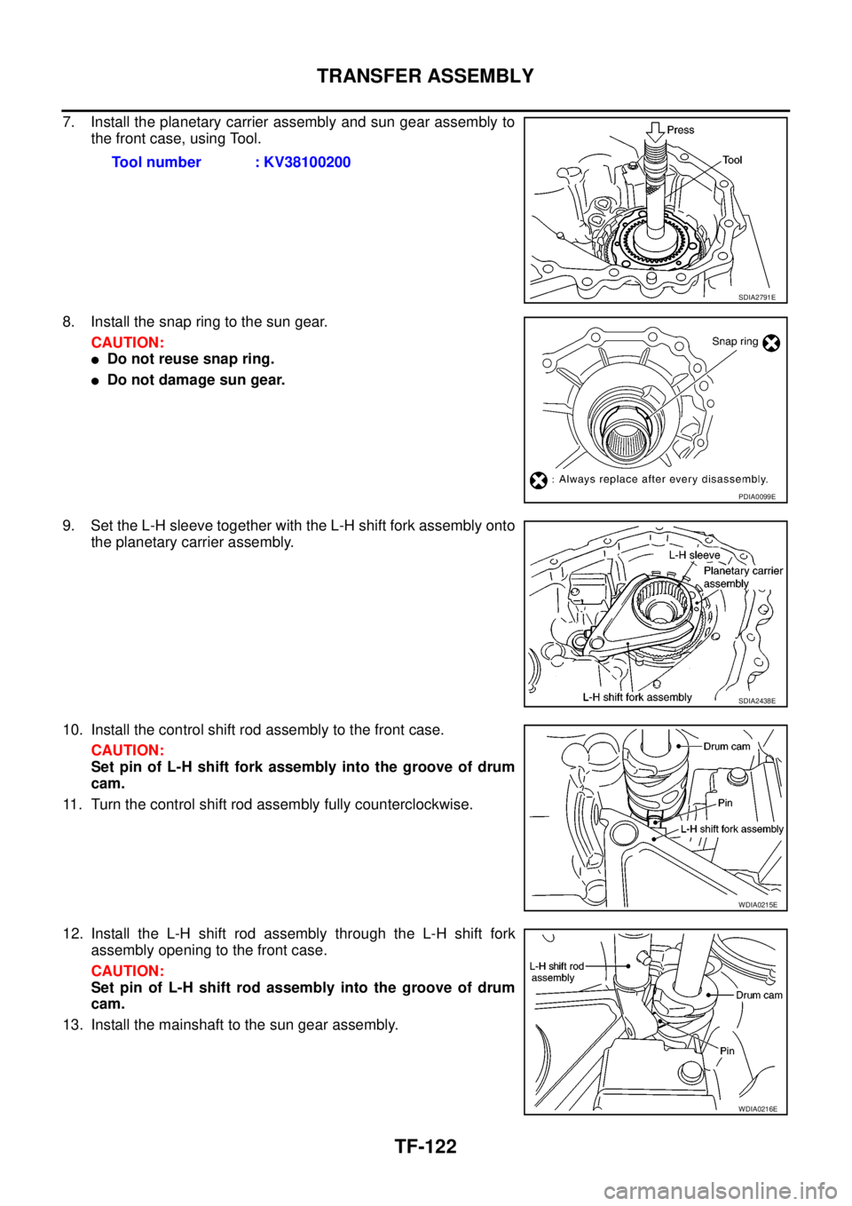
7. Install the planetary carrier assembly and sun gear assembly to
the front case, using Tool.
8. Install the snap ring to the sun gear.
CAUTION:
lDo not reuse snap ring.
lDo not damage sun gear.
9. Set the L-H sleeve together with the L-H shift fork assembly onto
the planetary carrier assembly.
10. Install the control shift rod assembly to the front case.
CAUTION:
Set pin of L-H shift fork assembly into the groove of drum
cam.
11. Turn the control shift rod assembly fully counterclockwise.
12. Install the L-H shift rod assembly through the L-H shift fork
assembly opening to the front case.
CAUTION:
Set pin of L-H shift rod assembly into the groove of drum
cam.
13. Install the mainshaft to the sun gear assembly.Tool number : KV38100200
SDIA2791E
PDIA0099E
SDIA2438E
WDIA0215E
WDIA0216E
Page 3090 of 3171
TRANSFER ASSEMBLY
TF-123
C
E
F
G
H
I
J
K
L
MA
B
TF
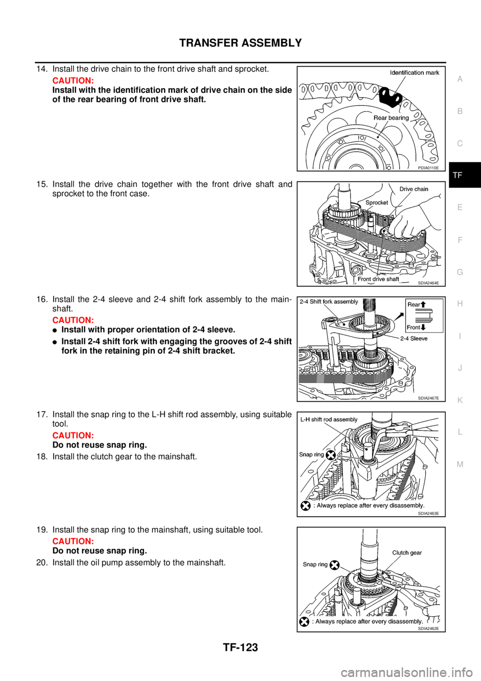
14. Install the drive chain to the front drive shaft and sprocket.
CAUTION:
Install with the identification mark of drive chain on the side
of the rear bearing of front drive shaft.
15. Install the drive chain together with the front drive shaft and
sprocket to the front case.
16. Install the 2-4 sleeve and 2-4 shift fork assembly to the main-
shaft.
CAUTION:
lInstall with proper orientation of 2-4 sleeve.
lInstall 2-4 shift fork with engaging the grooves of 2-4 shift
fork in the retaining pin of 2-4 shift bracket.
17. Install the snap ring to the L-H shift rod assembly, using suitable
tool.
CAUTION:
Do not reuse snap ring.
18. Install the clutch gear to the mainshaft.
19. Install the snap ring to the mainshaft, using suitable tool.
CAUTION:
Do not reuse snap ring.
20. Install the oil pump assembly to the mainshaft.
PDIA0110E
SDIA2464E
SDIA2467E
SDIA2463E
SDIA2462E
Trending: bulb, spare wheel, fuse box, ABS, fuel pressure, Timing marks, brake
