NISSAN NAVARA 2005 Repair Workshop Manual
Manufacturer: NISSAN, Model Year: 2005, Model line: NAVARA, Model: NISSAN NAVARA 2005Pages: 3171, PDF Size: 49.59 MB
Page 641 of 3171

POWER DOOR LOCK — SUPER LOCK —
BL-57
C
D
E
F
G
H
J
K
L
MA
B
BL
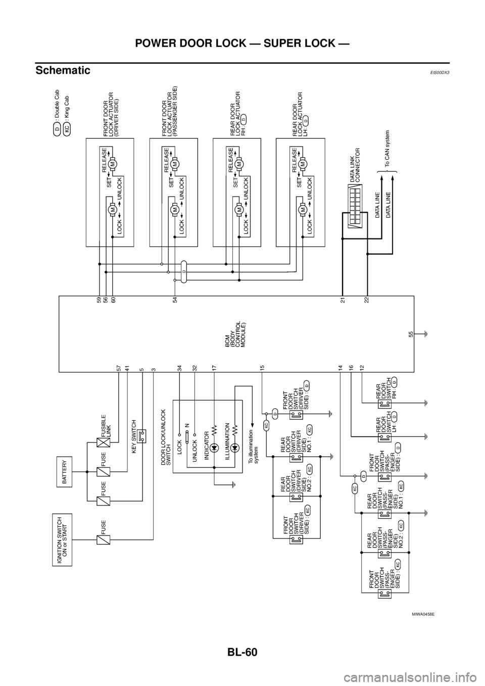
System DescriptionEIS00DX0
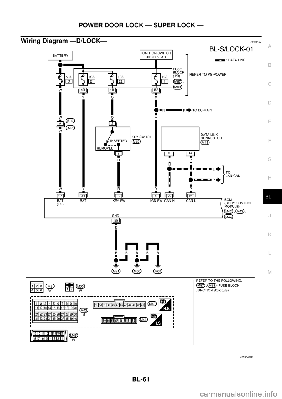
Power is supplied at all times
lthrough 50A fusible link (letterG, located in the fuse and fusible link box)
lto BCM terminal 57
lthrough 10A fuse [No. 21, located in the fuse block (J/B)]
lto BCM terminal 41
lthrough 10A fuse [No. 22, located in the fuse block (J/B)]
lto key switch terminal 2.
When key switch is ON, power is supplied
lthrough key switch terminal 1
lto BCM terminal 5.
When ignition switch is in ON or START position
lthrough 10A fuse [No. 1, located in the fuse block (J/B)]
lto BCM terminal 3.
Ground is supplied
lto BCM terminal 55
lthrough body grounds M21, M80 and M83.
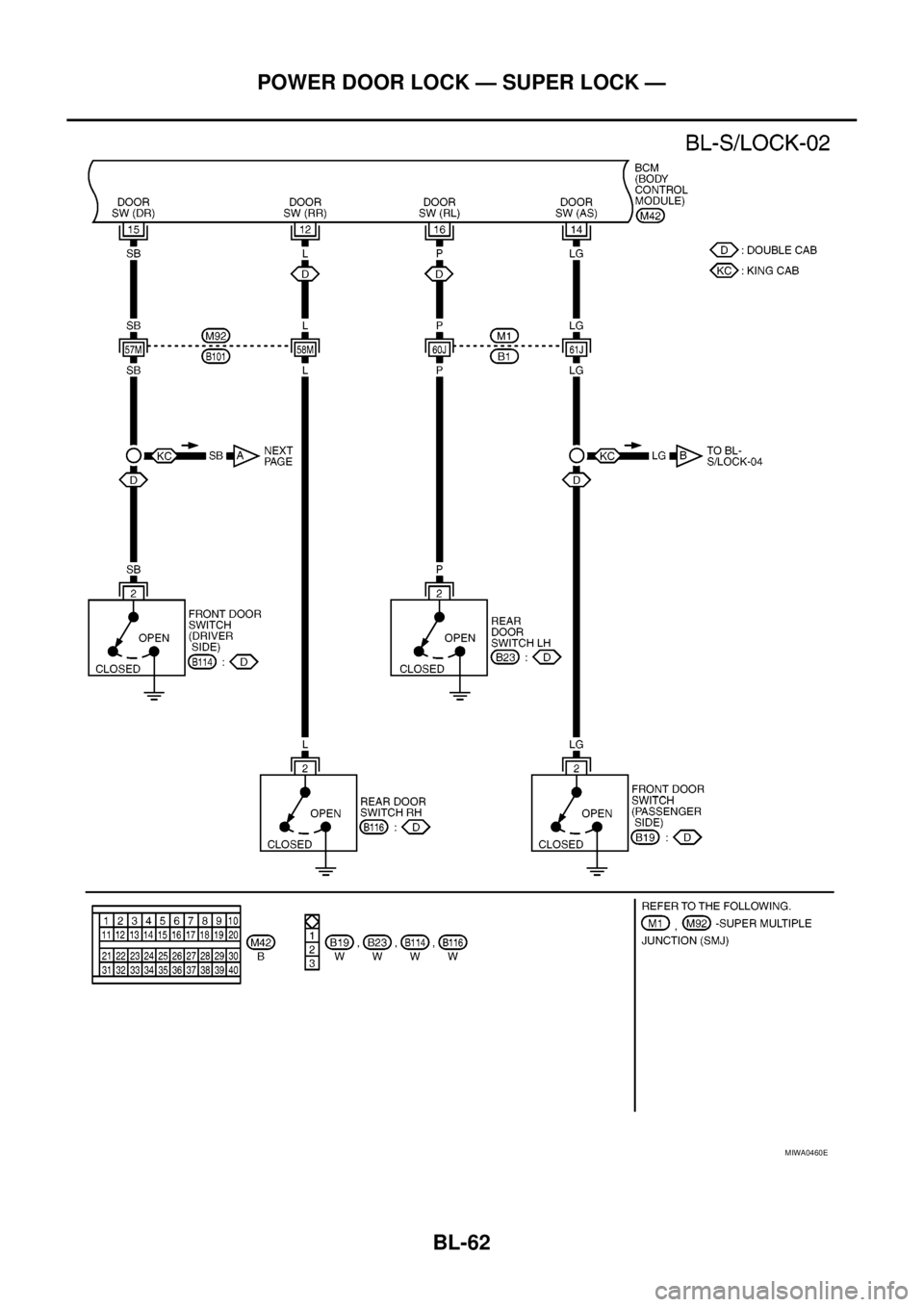
Door switch operation
When front door switch (driver side) is ON (door is OPEN), ground is supplied
lto BCM terminal 15
lthrough front door switch (driver side) terminal 2
lthrough front door switch (driver side) case ground.
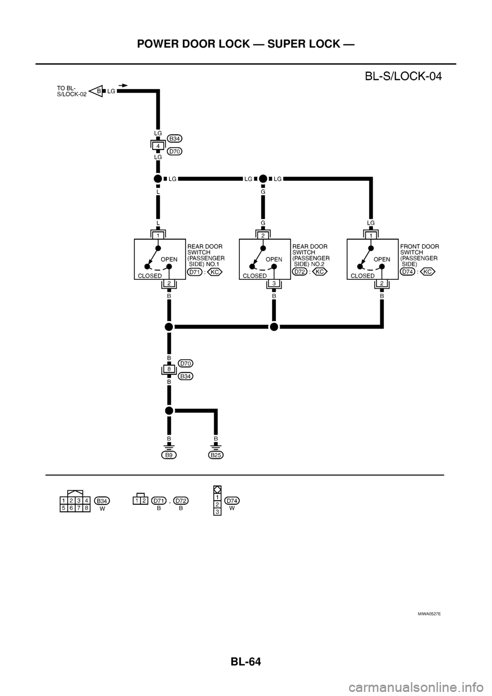
When front door switch (passenger side) is ON (door is OPEN), ground is supplied
lto BCM terminal 14
lthrough front door switch (passenger side) terminal 2
lthrough front door switch (passenger side) case ground.
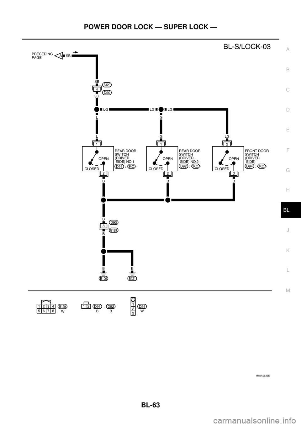
When rear door switch LH is ON (door is OPEN), ground is supplied (Double cab models)
lto BCM terminal 16
lthrough rear door switch LH terminal 2
lthrough rear door switch LH case ground.
When rear door switch RH is ON (door is OPEN), ground is supplied (Double cab models)
lto BCM terminal 12
lthrough rear door switch RH terminal 2
lthrough rear door switch RH case ground.
Super lock set/release operation
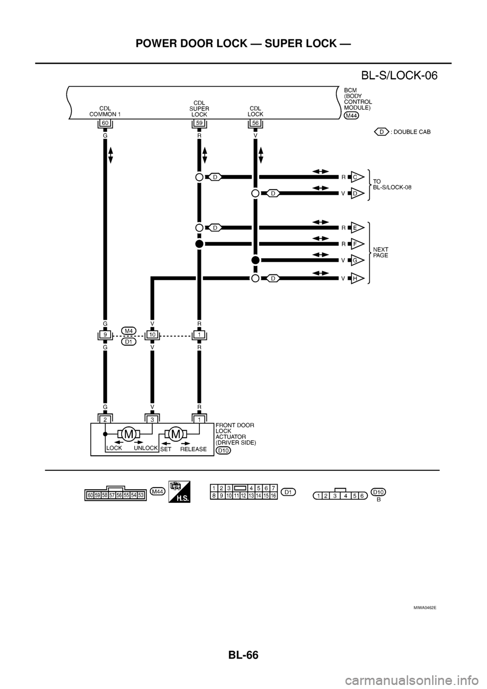
When super lock is set, ground is supplied
lThrough BCM terminals 59
lThrough each super lock actuators terminals 1 and 2
lTo BCM terminal 60
When super lock is released, ground is supplied
lThrough BCM terminal 60
lThrough each super lock actuators terminals 2 and 1
lTo BCM terminals 59
Power door lock operation with door lock/unlock switch
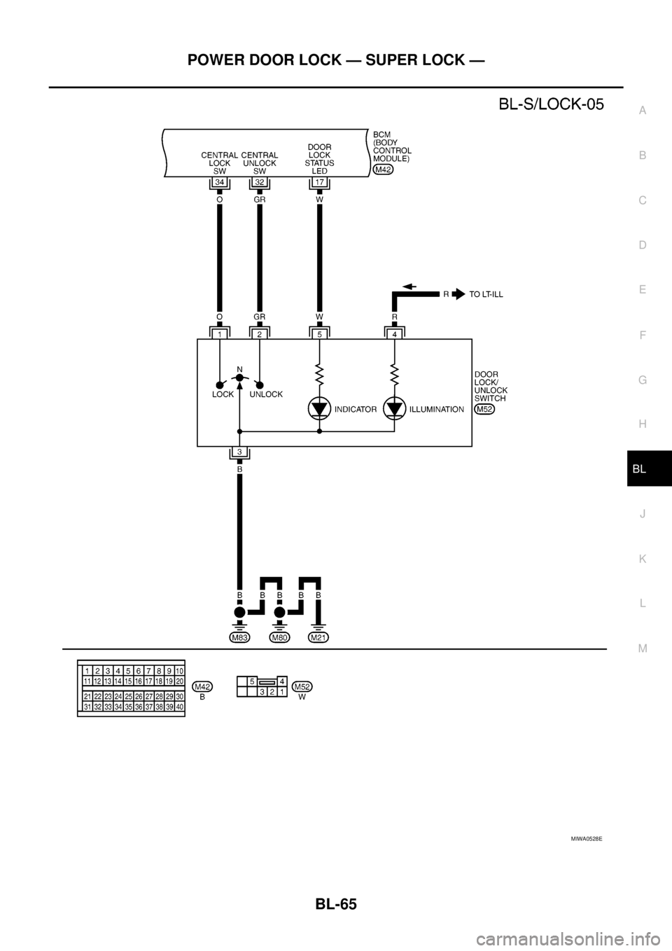
When doors are lock by door lock/unlock switch, ground is supplied
lto BCM terminal 34
lthrough door lock /unlock switch terminals 1 and 3
lthrough body grounds M21, M80 and M83.
then all doors are locked.
Page 642 of 3171

BL-58
POWER DOOR LOCK — SUPER LOCK —
When door lock/unlock switch is locked, ground is supplied
lthrough BCM terminal 56
lthrough all door actuators terminal 3
lthrough all door lock actuators terminal 2
lthrough back door lock actuator terminals 1 and 3
lto BCM terminals 54 and 60.
then all doors actuators are locked
Power door unlock operation with door lock/unlock switch
When doors are unlock by door lock/unlock switch, ground is supplied
lto BCM terminal 32
lthrough door lock/unlock switch terminals 2 and 3
lthrough body grounds M21, M80 and M83.
then all doors are locked.
When door lock/unlock switch is unlocked, ground is supplied
lthrough BCM terminals 54 and 60
lthrough all door lock actuators terminal 2
lthrough all door lock actuators terminal 3
lthen all door actuators are unlock
lto BCM terminal 56.
Door lock/unlock switch indicator operation
When door lock/unlock switch is locked, all doors are locked, door lock/unlock switch indicator is on, and
ground is supplied
lto BCM terminal 17
lthrough door lock/unlock switch terminals 5 and 3
lthrough body grounds M21, M80 and M83.
OUTLINE
Power door lock systems with super lock function provides a higher anti-theft performance than conventional
power door lock systems. The super lock system is controlled by BCM (Body Control Module).
Pressing LOCK button on key fob once will lock all doors and activate super lock simultaneously.
When super lock is set, all doors cannot be opened from inside.
Pressing UNLOCK button once on key fob will unlock driver side door (unlock all doors if anti-hijack system is
disabled and during this state, super lock is still active). Second press on the UNLOCK button within 5 second
from the first will unlock all doors and release super lock simultaneously.
Functions Available By Operating the Door Lock/Unlock Switch
lOperating the door lock/unlock switch in the control panel will activate all doors actuator to lock or unlock.
If any doors are opened (except the driver side) during operating the door lock/unlock switch in lock direc-
tion, the door lock actuators will not response. Unlock via the interior door handles and door lock/unlock
switch is always possible.
lOperating the door lock/unlock switch to “LOCK” will lock the vehicle even while driver side door is
opened.
OPERATION
Set Super Lock Conditions
lWhen all these following conditions are met, BCM receives lock signal from key fob.
–All doors are closed.
–Key is out of the ignition key cylinder.
Release Super Lock Conditions
lBCM unit receives a valid unlock signal from key fob.
lIgnition switch is turned ON (door lock/unlock switch will remain its state, super lock is released).
NOTE:
Door lock/unlock switch is incapable of overriding super lock.
Page 643 of 3171
POWER DOOR LOCK — SUPER LOCK —
BL-59
C
D
E
F
G
H
J
K
L
MA
B
BL
Door Lock Warning Function
Under following conditions lock actuators will not response and buzzer warning will beeps while pressing door
lock/unlock switch in LOCK direction.
lIgnition switch is turned OFF
lMechanical key is out of ignition key cylinder
lAny door is opened (except driver side door)
Key Reminder Function
Under following conditions lock actuators will lock the door once, but then immediately unlock all doors and
buzzer warning will beeps while pressing door lock/unlock switch in LOCK direction.
lIgnition switch is turned OFF
lMechanical key is inserted in ignition key cylinder
lDriver side door is opened
Door Lock/Unlock Switch Indicator
The Door lock/unlock switch indicates door lock status. The indicator will illuminate when a lock operation is
accomplish, during this state, if any door is open, the indicator will turn OFF.
Door Lock Indicator Timer
Door lock indicator timer is designed to reacts and shut down the indicator. The default timer values are 1
minute and 30 minutes.
lWhen the lock operation is activated by keyfob or auto door lock (for further details refer toBL-92, "Auto
Re-lock Function"), then the illuminate time is set to 1 minute.
lWhen the lock operation is activated by door lock/unlock switch, then the timer is set to 30 minutes.
NOTE:
When the 30 minutes timer is active and ignition switch is turned ON, then the indicator illuminate for per-
manently unless ignition switch is turned OFF then timer will be reset back to 30 minutes.
CAN Communication System DescriptionEIS00DX1
CAN (Controller Area Network) is a serial communication line for real time application. It is an on-vehicle mul-
tiplex communication line with high data communication speed and excellent error detection ability. Many elec-
tronic control units are equipped onto a vehicle, and each control unit shares information and links with other
control units during operation (not independent). In CAN communication, control units are connected with 2
communication lines (CAN H line, CAN L line) allowing a high rate of information transmission with less wiring.
Each control unit transmits/receives data but selectively reads required data only.
CAN Communication UnitEIS00DX2
Refer toLAN-23, "CAN COMMUNICATION".
Page 644 of 3171
BL-60
POWER DOOR LOCK — SUPER LOCK —
Schematic
EIS00DX3
MIWA0458E
Page 645 of 3171
POWER DOOR LOCK — SUPER LOCK —
BL-61
C
D
E
F
G
H
J
K
L
MA
B
BL
Wiring Diagram —D/LOCK—EIS00DX4
MIWA0459E
Page 646 of 3171
BL-62
POWER DOOR LOCK — SUPER LOCK —
MIWA0460E
Page 647 of 3171
POWER DOOR LOCK — SUPER LOCK —
BL-63
C
D
E
F
G
H
J
K
L
MA
B
BL
MIWA0526E
Page 648 of 3171
BL-64
POWER DOOR LOCK — SUPER LOCK —
MIWA0527E
Page 649 of 3171
POWER DOOR LOCK — SUPER LOCK —
BL-65
C
D
E
F
G
H
J
K
L
MA
B
BL
MIWA0528E
Page 650 of 3171
BL-66
POWER DOOR LOCK — SUPER LOCK —
MIWA0462E