NISSAN NAVARA 2005 Repair Workshop Manual
Manufacturer: NISSAN, Model Year: 2005, Model line: NAVARA, Model: NISSAN NAVARA 2005Pages: 3171, PDF Size: 49.59 MB
Page 601 of 3171
HOOD
BL-17
C
D
E
F
G
H
J
K
L
MA
B
BL
Hood Lock Control InspectionEIS00BQ1
CAUTION:
If the hood lock cable is bent or deformed, replace it.
1. Make sure that the hood lock secondary latch is properly engaged with the secondary striker with hood's
own weight.
2. Make sure that the hood lock primary latch is securely engaged with the hood striker with hood's own
weight by dropping it from approx. 200 mm (7.87 in) height.
CAUTION:
Do not drop hood from a height of 300 mm (11.81 in) or more.
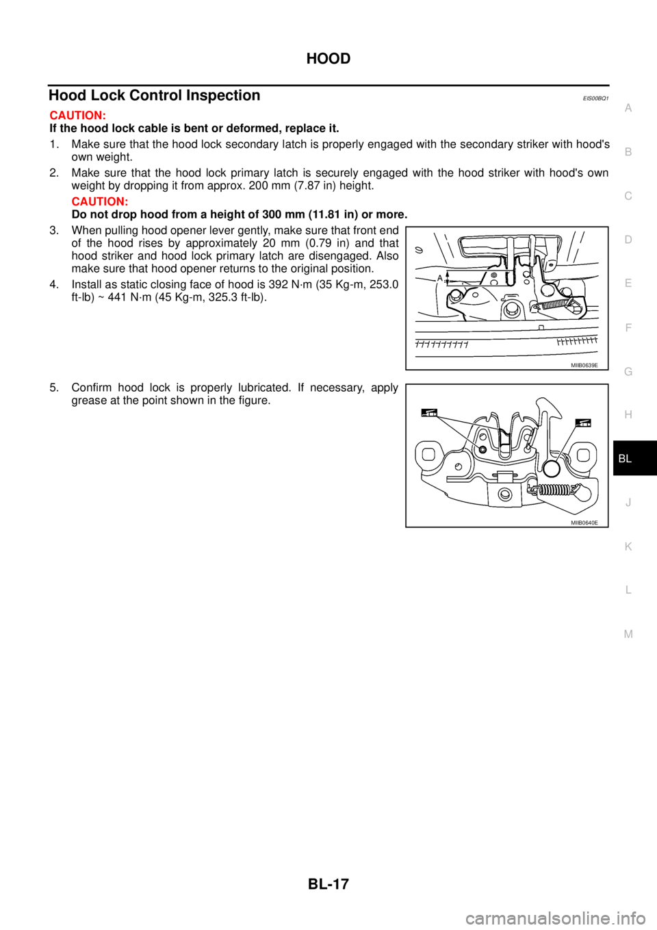
3. When pulling hood opener lever gently, make sure that front end
of the hood rises by approximately 20 mm (0.79 in) and that
hood striker and hood lock primary latch are disengaged. Also
make sure that hood opener returns to the original position.
4. Install as static closing face of hood is 392 N·m (35 Kg-m, 253.0
ft-lb) ~ 441 N·m (45 Kg-m, 325.3 ft-lb).
5. Confirm hood lock is properly lubricated. If necessary, apply
grease at the point shown in the figure.
MIIB0639E
MIIB0640E
Page 602 of 3171
BL-18
RADIATOR CORE SUPPORT
RADIATOR CORE SUPPORT
PFP:62500
Removal and InstallationEIS00DGJ
REMOVAL
1. Remove the hood assembly. Refer toBL-14, "Removal and Installation of Hood Assembly".
2. Remove the front grille. Refer toEI-19, "
FRONT GRILLE".
3. Remove the front bumper, bumper reinforcement and bumper bracket. Refer toEI-15, "
FRONT BUMPER"
.
4. Remove the headlamp assembly (LH/RH). Refer toLT-30, "
Removal and Installation".
5. Remove the air intake duct (Air guide). Refer toEM-15, "
AIR CLEANER AND AIR DUCT".
6. Remove the charge air cooler. (for YD25 engine models only) Refer toEM-18, "
CHARGE AIR COOLER".
7. Remove the power steering oil cooler. Refer toPS-30, "
HYDRAULIC LINE".
8. Remove the A/T fluid cooler and A/T fluid cooler tube mounting nuts. Refer toAT- 2 4 4 , "
A/T FLUID
COOLER".
9. Remove the hood lock assembly, and then remove the hood lock cable. Refer toBL-15, "
Removal and
Installation of Hood Lock Control".
10. Remove the horn harness connector.
11. Disconnect the ambient sensor connector and remove the ambient sensor. Refer toAT C - 11 7 , "
Removal
and Installation".
12. Remove the mounting harness clip on radiator core support assembly, the harness is separate.
13. Remove the upper radiator bracket. Refer toCO-11, "
RADIATOR".
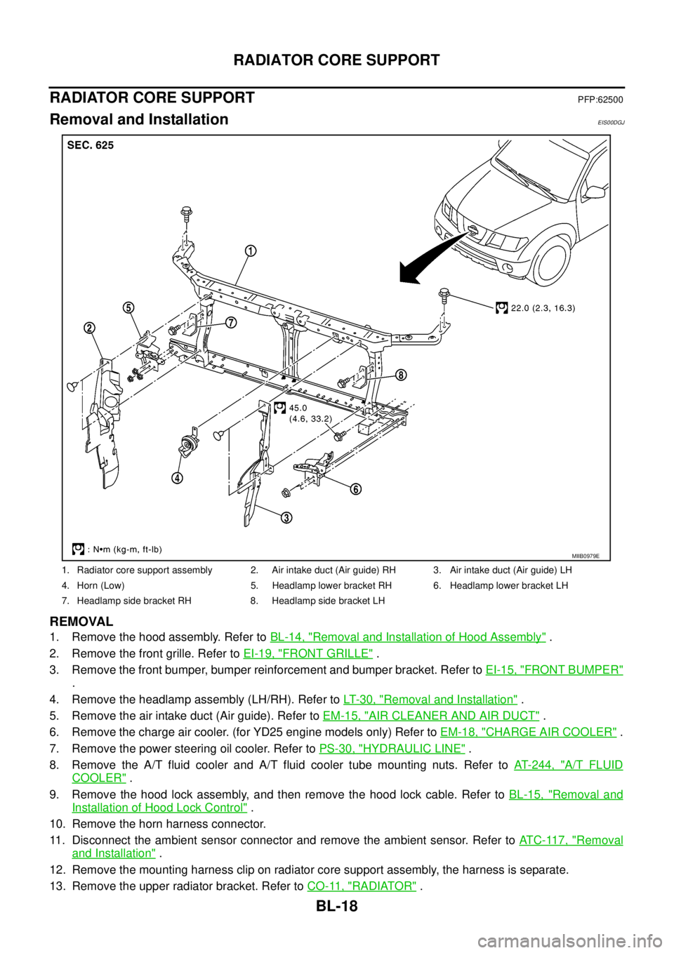
1. Radiator core support assembly 2. Air intake duct (Air guide) RH 3. Air intake duct (Air guide) LH
4. Horn (Low) 5. Headlamp lower bracket RH 6. Headlamp lower bracket LH
7. Headlamp side bracket RH 8. Headlamp side bracket LH
MIIB0979E
Page 603 of 3171
RADIATOR CORE SUPPORT
BL-19
C
D
E
F
G
H
J
K
L
MA
B
BL
14. Remove the radiator core support mounting bolts and remove the radiator core support assembly.
15. After removing the radiator core support assembly, the following parts are separate.
lHorn (Low).
lHeadlamp side bracket (LH/RH).
lHeadlamp lower bracket (LH/RH).
INSTALLATION
Install in the reverse order of removal.
CAUTION:
After installing, check the hood adjustment and hood opener operation. Refer toBL-12, "
Fitting
Adjustment"andBL-17, "Hood Lock Control Inspection".
Page 604 of 3171
BL-20
FRONT FENDER
FRONT FENDER
PFP:63100
Removal and InstallationEIS00BK0
REMOVAL
1. Remove the front bumper. Refer toEI-15, "FRONT BUMPER".
2. Remove the headlamp. Refer toLT-30, "
Removal and Installation".
3. Remove the front fender protector. Refer toEI-22, "
Removal and Installation of Front Fender Protector".
4. Remove the front side turn signal lamp. Refer toLT- 111 , "
Removal and Installation of Front Turn Signal
Lamp".
5. Remove the front fender mounting bolt and remove the front fender.
CAUTION:
While removing use a shop cloth to protect body from damaging.
INSTALLATION
Install in the reverse order of removal.
CAUTION:
lAfter installing, apply touch-up paint (the body color) onto the head of the front fender mounting
bolts.
lAfter installing, check front fender adjustment. Refer toBL-117, "Fitting Adjustment (King Cab)"
andBL-12, "Fitting Adjustment"andBL-119, "Fitting Adjustment (Double Cab)".
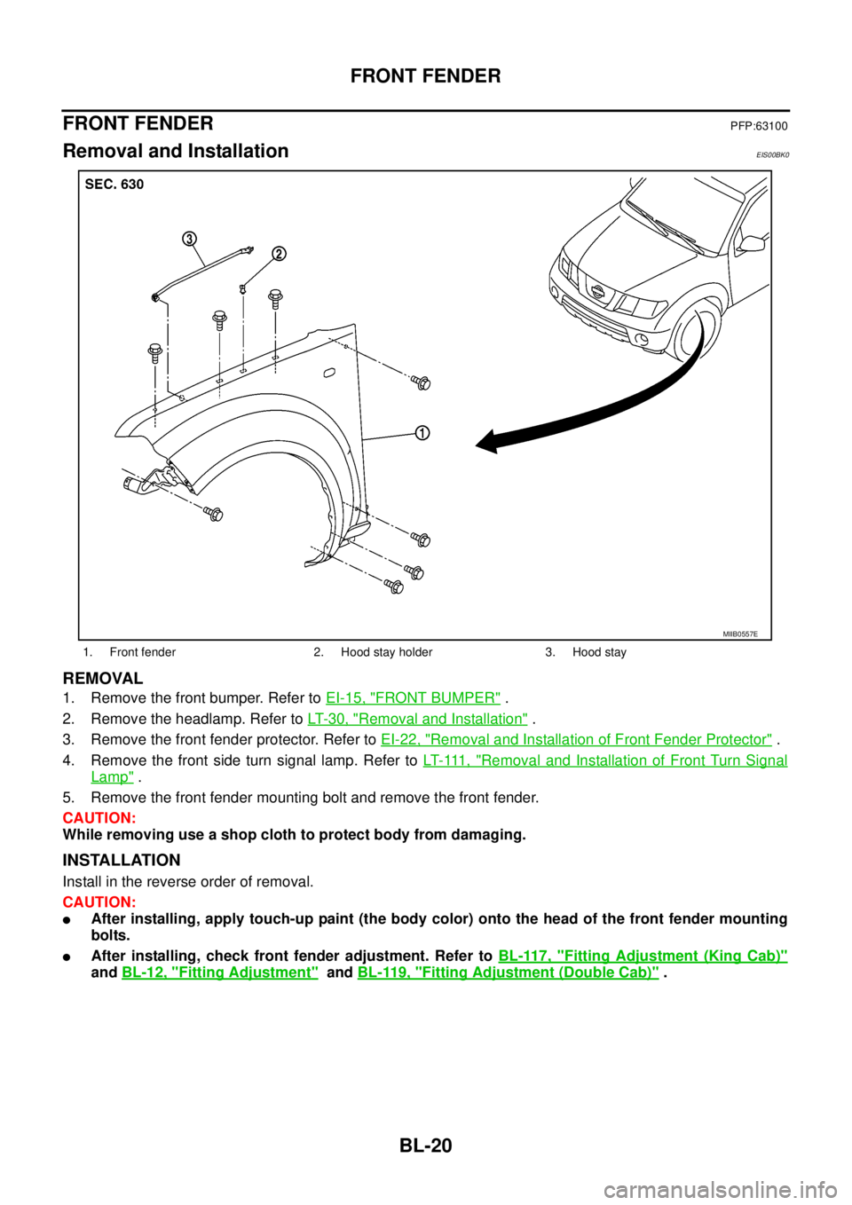
1. Front fender 2. Hood stay holder 3. Hood stay
MIIB0557E
Page 605 of 3171
POWERDOORLOCKSYSTEM
BL-21
C
D
E
F
G
H
J
K
L
MA
B
BL
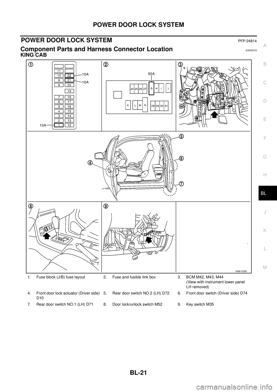
POWER DOOR LOCK SYSTEMPFP:24814
Component Parts and Harness Connector LocationEIS00D7Q
KING CAB
1. Fuse block (J/B) fuse layout 2. Fuse and fusible link box 3. BCM M42, M43, M44
(View with instrument lower panel
LH removed)
4. Front door lock actuator (Driver side)
D105. Rear door switch NO.2 (LH) D72 6. Front door switch (Driver side) D74
7. Rear door switch NO.1 (LH) D71 8. Door lock/unlock switch M52 9. Key switch M35
MIIB1028E
Page 606 of 3171
BL-22
POWER DOOR LOCK SYSTEM
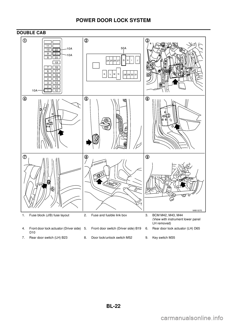
DOUBLE CAB
1. Fuse block (J/B) fuse layout 2. Fuse and fusible link box 3. BCM M42, M43, M44
(View with instrument lower panel
LH removed)
4. Front door lock actuator (Driver side)
D105. Front door switch (Driver side) B19 6. Rear door lock actuator (LH) D65
7. Rear door switch (LH) B23 8. Door lock/unlock switch M52 9. Key switch M35
MIIB1027E
Page 607 of 3171

POWERDOORLOCKSYSTEM
BL-23
C
D
E
F
G
H
J
K
L
MA
B
BL
System DescriptionEIS00D7R
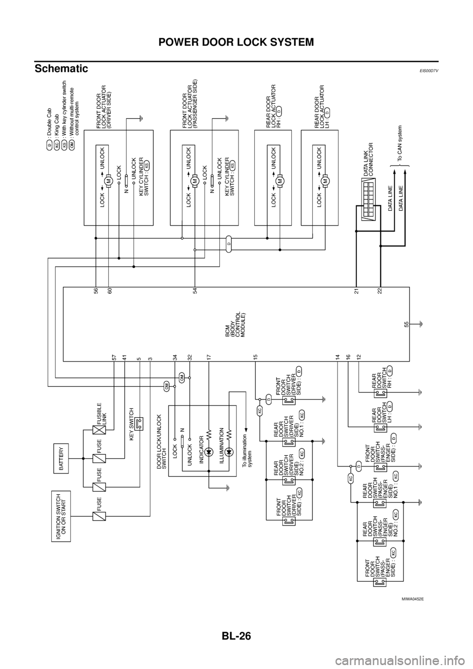
Power is supplied at all times
lthrough 50A fusible link (letterG, located in the fuse and fusible link box)
lto BCM terminal 57
lthrough 10A fuse [No. 21, located in the fuse block (J/B)]
lto BCM terminal 41
lthrough 10A fuse [No. 22, located in the fuse block (J/B)]
lto key switch terminal 2.
When key switch is ON, power is supplied
lthrough key switch terminal 1
lto BCM terminal 5.
When ignition switch is in ON or START position
lthrough 10A fuse [No. 1, located in the fuse block (J/B)]
lto BCM terminal 3.
Ground is supplied
lto BCM terminal 55
lthrough body grounds M21, M80 and M83.
Door switch operation
When front door switch (driver side) is ON (door is OPEN), ground is supplied
lto BCM terminal 15
lthrough front door switch (driver side) terminal 2
lthrough front door switch (driver side) case ground.
When front door switch (passenger side) is ON (door is OPEN), ground is supplied
lto BCM terminal 14
lthrough front door switch (passenger side) terminal 2
lthrough front door switch (passenger side) case ground.
When rear door switch LH is ON (door is OPEN), ground is supplied (Double cab model)
lto BCM terminal 16
lthrough rear door switch LH terminal 2
lthrough rear door switch LH case ground.
When rear door switch RH is ON (door is OPEN), ground is supplied (Double cab model)
lto BCM terminal 12
lthrough rear door switch RH terminal 2
lthrough rear door switch RH case ground.
Key cylinder switch operation (Without multi-remote control system)
When key cylinder is turned to lock position, ground is supplied
lthrough BCM terminal 34
lto key cylinder switch (driver and passenger side) terminals 4
lthrough key cylinder switch (driver and passenger side) terminals 5
lthrough body ground M21, M80 and M83
then all doors are locked.
When key cylinder is turned to unlock position, ground is supplied
lthrough BCM terminal 32
lto key cylinder switch (driver and passenger side) terminal 6
lthrough key cylinder switch (driver and passenger side) terminal 5
lthrough body ground M21, M80 and M83
then all doors are unlocked.
Power door lock operation with door lock/unlock switch
When doors are lock by door lock/unlock switch, ground is supplied
Page 608 of 3171

BL-24
POWER DOOR LOCK SYSTEM
lto BCM terminal 34
lthrough door lock /unlock switch terminals 1 and 3
lthrough body grounds M21, M80 and M83.
then all doors are locked.
When door lock/unlock switch is locked, ground is supplied
lthrough BCM terminal 56
lthrough all door actuators terminal 3
lthrough all door lock actuators terminal 2
lthrough back door lock actuator terminals 1 and 3
lto BCM terminals 54 and 60.
then all doors actuators are locked
Power door unlock operation with door lock/unlock switch
When doors are unlock by door lock/unlock switch, ground is supplied
lto BCM terminal 32
lthrough door lock/unlock switch terminals 2 and 3
lthrough body grounds M21, M80 and M83.
then all doors are locked.
When door lock/unlock switch is unlocked, ground is supplied
lthrough BCM terminals 54 and 60
lthrough all door lock actuators terminal 2
lthrough all door lock actuators terminal 3
lthen all door actuators are unlock
lto BCM terminal 56.
Door lock/unlock switch indicator operation
When door lock/unlock switch is locked, all doors are locked, door lock/unlock switch indicator is on, and
ground is supplied
lto BCM terminal 17
lthrough door lock/unlock switch terminals 5 and 3
lthrough body grounds M21, M80 and M83.
OUTLINE
Function Available by Operating the Door Lock/Unlock Switch
lOperating the door lock/unlock switch to “LOCK” will lock all doors.
lOperating the door lock/unlock switch to “UNLOCK” will unlock all doors.
NOTE:
Unlock via the interior door handles and door lock/unlock switch is always possible.
Door Lock Warning Function
Under following conditions lock actuators will not respond and buzzer warning will beeps while pressing door
lock/unlock switch in LOCK direction.
lIgnition switch is turned OFF
lMechanical key is out of ignition key cylinder
lDoor is opened (except driver side door)
Key Reminder Function
Under following conditions lock actuators will lock the door once, but then immediately unlock all doors and
buzzer warning will beeps while pressing door lock/unlock switch in LOCK direction.
lIgnition switch is turned OFF
lMechanical key is inserted in ignition key cylinder
lDriver side door is opened
Door Lock/Unlock Switch Indicator
The Door lock/unlock switch indicates door lock status. The indicator will illuminates when a lock operation is
accomplish, during this state, if any door is open, the indicator will turn OFF.
Page 609 of 3171
POWERDOORLOCKSYSTEM
BL-25
C
D
E
F
G
H
J
K
L
MA
B
BL
Door lock indicator timer
Door lock indicator timer is designed to reacts and shut down the indicator. The default timer values are 1
minute and 30 minutes.
lWhen the lock operation is activated by keyfob or auto door lock (for further details, refer toBL-92, "Auto
Re-lock Function"), then the illuminate time is set to 1 minute.
lWhen the lock operation is activated by door lock/unlock switch, then the timer is set to 30 minutes.
NOTE:
When the 30 minutes timer is active and ignition switch is turned ON, the indicator illuminate for perma-
nently, unless ignition switch is turned OFF then timer will be reset back to 30 minutes.
CAN Communication System DescriptionEIS00D7T
CAN (Controller Area Network) is a serial communication line for real time application. It is an on-vehicle mul-
tiplex communication line with high data communication speed and excellent error detection ability. Many elec-
tronic control units are equipped onto a vehicle, and each control unit shares information and links with other
control units during operation (not independent). In CAN communication, control units are connected with 2
communication lines (CAN H line, CAN L line) allowing a high rate of information transmission with less wiring.
Each control unit transmits/receives data but selectively reads required data only.
CAN Communication UnitEIS00D7U
Refer toLAN-23, "CAN COMMUNICATION".
Page 610 of 3171
BL-26
POWER DOOR LOCK SYSTEM
Schematic
EIS00D7V
MIWA0452E