NISSAN NAVARA 2005 Repair Workshop Manual
Manufacturer: NISSAN, Model Year: 2005, Model line: NAVARA, Model: NISSAN NAVARA 2005Pages: 3171, PDF Size: 49.59 MB
Page 861 of 3171
![NISSAN NAVARA 2005 Repair Workshop Manual SENSOR ROTOR
BRC-39
[ABS]
C
D
E
G
H
I
J
K
L
MA
B
BRC
SENSOR ROTORPFP:47970
Removal and InstallationEFS005UF
FRONT
The sensor rotors are built into the wheel hubs and are not removable. If damaged, rep NISSAN NAVARA 2005 Repair Workshop Manual SENSOR ROTOR
BRC-39
[ABS]
C
D
E
G
H
I
J
K
L
MA
B
BRC
SENSOR ROTORPFP:47970
Removal and InstallationEFS005UF
FRONT
The sensor rotors are built into the wheel hubs and are not removable. If damaged, rep](/img/5/57362/w960_57362-860.png)
SENSOR ROTOR
BRC-39
[ABS]
C
D
E
G
H
I
J
K
L
MA
B
BRC
SENSOR ROTORPFP:47970
Removal and InstallationEFS005UF
FRONT
The sensor rotors are built into the wheel hubs and are not removable. If damaged, replace wheel hub and
bearing assembly. Refer toFAX-5, "
Removal and Installation".
REAR
Removal
1. Remove axle shaft assembly. Refer toRAX-7, "Removal and Installation".
NOTE:
It is necessary to assemble the rear axle to replace the sensor rotor.
2. Pull the sensor rotor of off the axle shaft using Tool and a press.
Installation
1. Install new sensor rotor on axle shaft using a suitable length
steel tube and a press. Make sure sensor rotor is fully seated.
CAUTION:
Do not reuse the old sensor rotor.
2. Install axle shaft assembly. Refer toRAX-7, "
Removal and
Installation".
CAUTION:
Do not reuse the axle oil seal. The axle oil seal must be
replaced every time the axle shaft assembly is removed
from the axle shaft housing.
WFIA0341E
Page 862 of 3171
![NISSAN NAVARA 2005 Repair Workshop Manual BRC-40
[ABS]
ACTUATOR AND ELECTRIC UNIT (ASSEMBLY)
ACTUATOR AND ELECTRIC UNIT (ASSEMBLY)
PFP:47660
Removal and InstallationEFS005UG
CAUTION:
lBefore servicing, disconnect battery cables.
lTo remove br NISSAN NAVARA 2005 Repair Workshop Manual BRC-40
[ABS]
ACTUATOR AND ELECTRIC UNIT (ASSEMBLY)
ACTUATOR AND ELECTRIC UNIT (ASSEMBLY)
PFP:47660
Removal and InstallationEFS005UG
CAUTION:
lBefore servicing, disconnect battery cables.
lTo remove br](/img/5/57362/w960_57362-861.png)
BRC-40
[ABS]
ACTUATOR AND ELECTRIC UNIT (ASSEMBLY)
ACTUATOR AND ELECTRIC UNIT (ASSEMBLY)
PFP:47660
Removal and InstallationEFS005UG
CAUTION:
lBefore servicing, disconnect battery cables.
lTo remove brake tube, use flare nut wrench to prevent flare nuts and brake tube from being dam-
aged. To install, use flare nut torque wrench.
lDo not apply excessive impact to ABS actuator and electric unit (control unit), such as dropping it.
lDo not remove and install actuator by holding harness.
lAfter work is completed, bleed air from brake tube and hose. Refer toBR-11, "Bleeding Brake Sys-
tem".
REMOVAL
1. Disconnect ABS actuator and electric unit (control unit) connector.
2. Loosen brake tube flare nuts, then remove brake tubes from ABS actuator and electric unit (control unit).
3. Remove ABS actuator and electric unit (control unit) bracket mounting bolts.
4. Remove ABS actuator and electric unit (control unit) from vehicle.
1. To rear 2. From master cylinder secondary
side3. To front left
4. From master cylinder primary side 5. To front right 6. ABS actuator and electric unit (con-
trol unit)
7. Harness connector
Refer to GI section for symbol marks in the figure.
SFIA3016E
Page 863 of 3171
![NISSAN NAVARA 2005 Repair Workshop Manual ACTUATOR AND ELECTRIC UNIT (ASSEMBLY)
BRC-41
[ABS]
C
D
E
G
H
I
J
K
L
MA
B
BRC
INSTALLATION
Installation is the reverse order of removal.
NOTE:
After installing harness connector in the ABS actuator an NISSAN NAVARA 2005 Repair Workshop Manual ACTUATOR AND ELECTRIC UNIT (ASSEMBLY)
BRC-41
[ABS]
C
D
E
G
H
I
J
K
L
MA
B
BRC
INSTALLATION
Installation is the reverse order of removal.
NOTE:
After installing harness connector in the ABS actuator an](/img/5/57362/w960_57362-862.png)
ACTUATOR AND ELECTRIC UNIT (ASSEMBLY)
BRC-41
[ABS]
C
D
E
G
H
I
J
K
L
MA
B
BRC
INSTALLATION
Installation is the reverse order of removal.
NOTE:
After installing harness connector in the ABS actuator and electric unit (control unit), make sure connector is
securely locked.
Page 864 of 3171
![NISSAN NAVARA 2005 Repair Workshop Manual BRC-42
[ABS]
ACTUATOR AND ELECTRIC UNIT (ASSEMBLY) NISSAN NAVARA 2005 Repair Workshop Manual BRC-42
[ABS]
ACTUATOR AND ELECTRIC UNIT (ASSEMBLY)](/img/5/57362/w960_57362-863.png)
BRC-42
[ABS]
ACTUATOR AND ELECTRIC UNIT (ASSEMBLY)
Page 865 of 3171

CL-1
CLUTCH
C TRANSMISSION/TRANSAXLE
CONTENTS
D
E
F
G
H
I
J
K
L
M
SECTIONCL
A
B
CL
CLUTCH
PRECAUTIONS .......................................................... 2
Service Notice or Precautions .................................. 2
PREPARATION ........................................................... 3
Special Service Tools ............................................... 3
Commercial Service Tools ........................................ 3
NOISE, VIBRATION AND HARSHNESS (NVH)
TROUBLESHOOTING ................................................ 5
NVH Troubleshooting Chart ..................................... 5
CLUTCH PEDAL ........................................................ 6
On-Vehicle Inspection and Adjustment .................... 6
Removal and Installation .......................................... 7
COMPONENTS .................................................... 7
REMOVAL ............................................................. 7
INSPECTION AFTER REMOVAL ......................... 7
INSTALLATION ..................................................... 7
CLUTCH FLUID .......................................................... 8
Air Bleeding Procedure ............................................ 8
CLUTCH MASTER CYLINDER .................................. 9
Components ............................................................. 9
Removal and Installation .......................................... 9
REMOVAL ............................................................. 9
INSTALLATION ..................................................... 9
Disassembly and Assembly ................................... 10
DISASSEMBLY ................................................... 10
INSPECTION AFTER DISASSEMBLY ............... 10
ASSEMBLY ......................................................... 10
OPERATING CYLINDER ...........................................11
Components ............................................................ 11
Removal and Installation ......................................... 11REMOVAL ........................................................... 11
INSTALLATION ................................................... 12
Disassembly and Assembly .................................... 12
DISASSEMBLY ................................................... 12
INSPECTION AFTER DISASSEMBLY ................ 12
ASSEMBLY ......................................................... 12
CLUTCH PIPING ....................................................... 13
Removal and Installation ........................................ 13
CLUTCH RELEASE MECHANISM ........................... 14
Removal and Installation ........................................ 14
COMPONENTS ................................................... 14
REMOVAL ........................................................... 14
INSPECTION AFTER REMOVAL ....................... 15
INSTALLATION ................................................... 15
CLUTCH DISC, CLUTCH COVER AND FLYWHEEL... 17
Removal and Installation ........................................ 17
COMPONENTS ................................................... 17
REMOVAL ........................................................... 17
INSPECTION AND ADJUSTMENT AFTER
REMOVAL ........................................................... 17
INSTALLATION ................................................... 18
SERVICE DATA AND SPECIFICATIONS (SDS) ...... 20
Clutch Control System ............................................ 20
Clutch Master Cylinder ........................................... 20
Clutch Operating Cylinder ...................................... 20
Clutch Disc ............................................................. 20
Clutch Cover ........................................................... 20
Clutch Pedal ........................................................... 20
Page 866 of 3171
CL-2
PRECAUTIONS
PRECAUTIONS
PFP:00001
ServiceNoticeorPrecautionsECS00ICC
lRecommended clutch fluid is brake fluid “DOT 3” or “DOT 4”. Refer toMA-14, "RECOMMENDED FLUIDS
AND LUBRICANTS".
lDo not reuse drained clutch fluid.
lBe careful not to splash clutch fluid on painted areas.
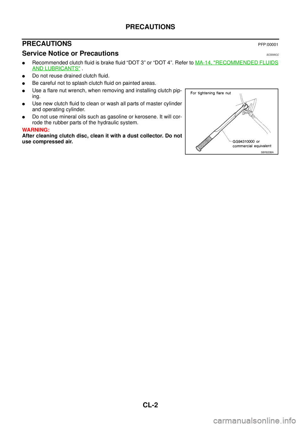
lUse a flare nut wrench, when removing and installing clutch pip-
ing.
lUse new clutch fluid to clean or wash all parts of master cylinder
and operating cylinder.
lDo not use mineral oils such as gasoline or kerosene. It will cor-
rode the rubber parts of the hydraulic system.
WARNING:
After cleaning clutch disc, clean it with a dust collector. Do not
use compressed air.
SBR820BA
Page 867 of 3171
PREPARATION
CL-3
D
E
F
G
H
I
J
K
L
MA
B
CL
PREPARATIONPFP:00002
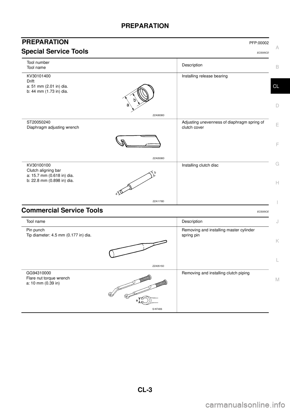
Special Service ToolsECS00ICD
Commercial Service ToolsECS00ICE
Tool number
Tool nameDescription
KV30101400
Drift
a: 51 mm (2.01 in) dia.
b: 44 mm (1.73 in) dia.Installing release bearing
ST20050240
Diaphragm adjusting wrenchAdjusting unevenness of diaphragm spring of
clutch cover
KV30100100
Clutch aligning bar
a: 15.7 mm (0.618 in) dia.
b: 22.8 mm (0.898 in) dia.Installing clutch disc
ZZA0838D
ZZA0508D
ZZA1178D
Tool nameDescription
Pin punch
Tip diameter: 4.5 mm (0.177 in) dia.Removing and installing master cylinder
spring pin
GG94310000
Flare nut torque wrench
a: 10 mm (0.39 in)Removing and installing clutch piping
ZZA0515D
S-NT406
Page 868 of 3171
CL-4
PREPARATION
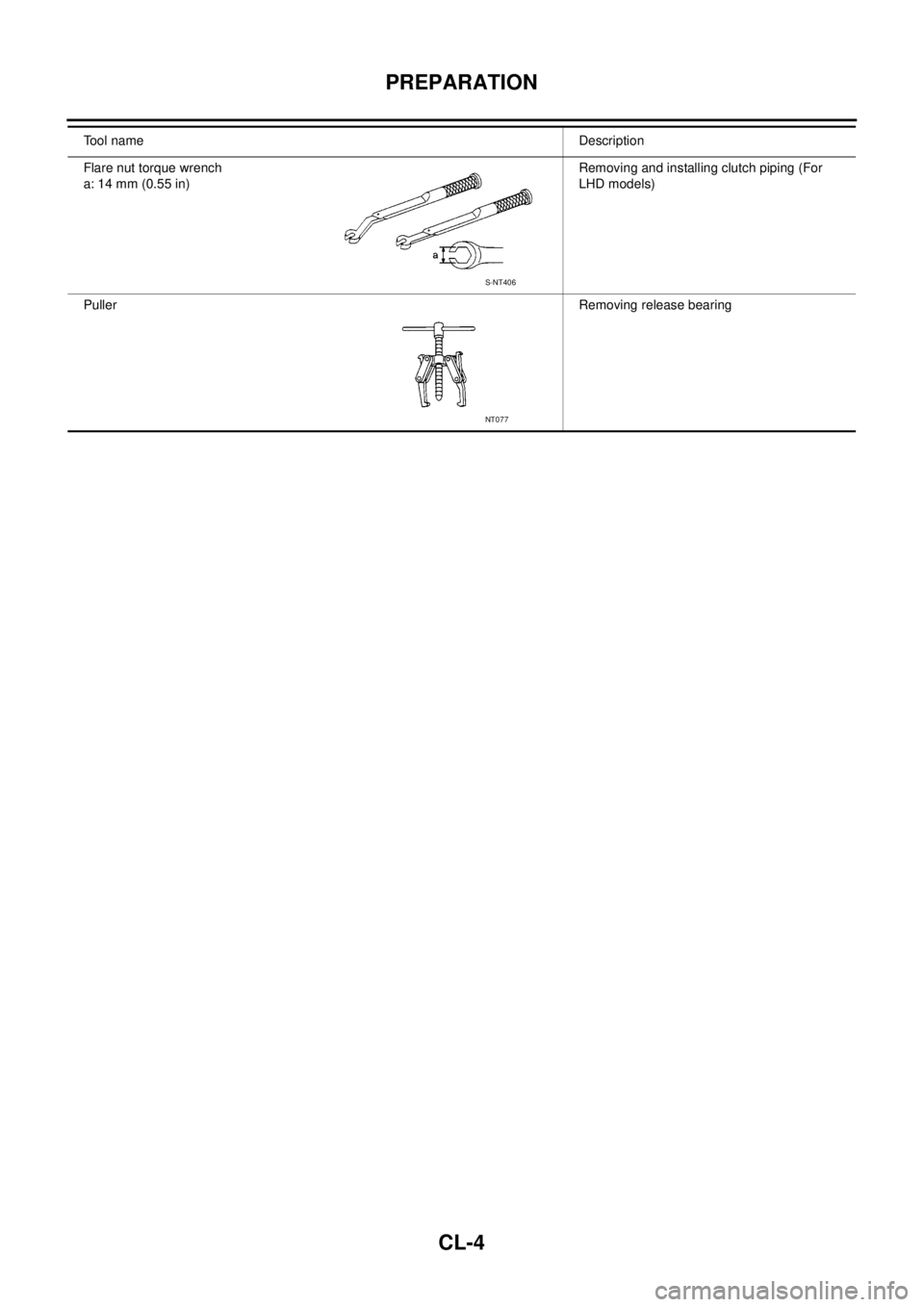
Flare nut torque wrench
a: 14 mm (0.55 in)Removing and installing clutch piping (For
LHD models)
PullerRemoving release bearing Tool nameDescription
S-NT406
NT077
Page 869 of 3171
NOISE, VIBRATION AND HARSHNESS (NVH) TROUBLESHOOTING
CL-5
D
E
F
G
H
I
J
K
L
MA
B
CL
NOISE, VIBRATION AND HARSHNESS (NVH) TROUBLESHOOTINGPFP:00003
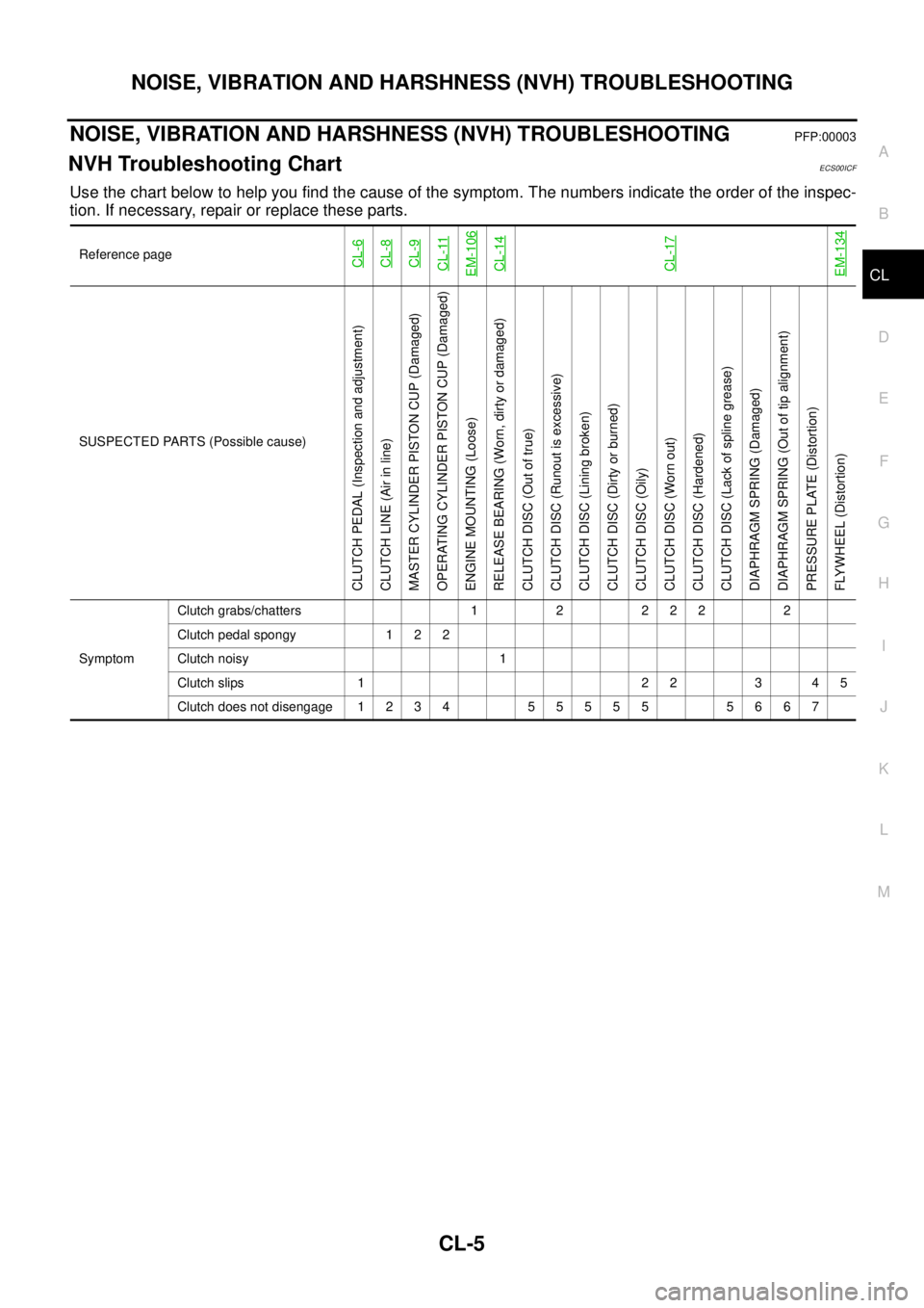
NVH Troubleshooting ChartECS00ICF
Use the chart below to help you find the cause of the symptom. The numbers indicate the order of the inspec-
tion. If necessary, repair or replace these parts.
Reference pageCL-6CL-8CL-9CL-11EM-106CL-14CL-17EM-134
SUSPECTED PARTS (Possible cause)
CLUTCH PEDAL (Inspection and adjustment)
CLUTCH LINE (Air in line)
MASTER CYLINDER PISTON CUP (Damaged)
OPERATING CYLINDER PISTON CUP (Damaged)
ENGINE MOUNTING (Loose)
RELEASE BEARING (Worn, dirty or damaged)
CLUTCH DISC (Out of true)
CLUTCH DISC (Runout is excessive)
CLUTCH DISC (Lining broken)
CLUTCH DISC (Dirty or burned)
CLUTCH DISC (Oily)
CLUTCH DISC (Worn out)
CLUTCH DISC (Hardened)
CLUTCH DISC (Lack of spline grease)
DIAPHRAGM SPRING (Damaged)
DIAPHRAGM SPRING (Out of tip alignment)
PRESSURE PLATE (Distortion)
FLYWHEEL (Distortion)
SymptomClutch grabs/chatters 1 2 2 2 2 2
Clutch pedal spongy 1 2 2
Clutch noisy 1
Clutch slips 1 2 2 3 4 5
Clutch does not disengage 1 2 3 4 5 5 5 5 5 5 6 6 7
Page 870 of 3171
CL-6
CLUTCH PEDAL
CLUTCH PEDAL
PFP:46540
On-Vehicle Inspection and AdjustmentECS00ICG
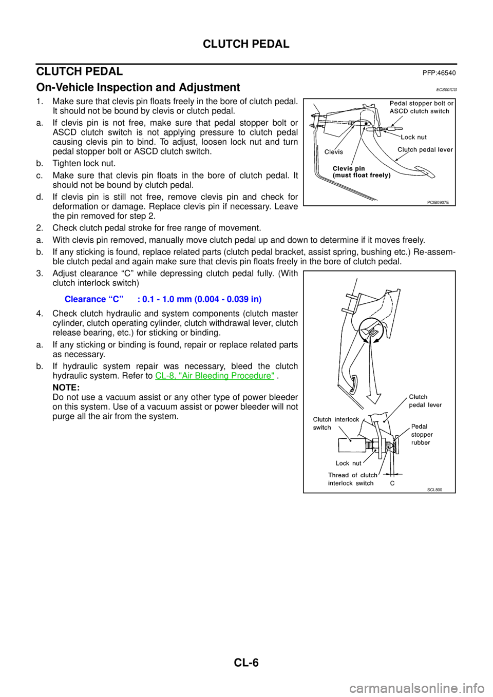
1. Make sure that clevis pin floats freely in the bore of clutch pedal.
It should not be bound by clevis or clutch pedal.
a. If clevis pin is not free, make sure that pedal stopper bolt or
ASCD clutch switch is not applying pressure to clutch pedal
causing clevis pin to bind. To adjust, loosen lock nut and turn
pedal stopper bolt or ASCD clutch switch.
b. Tighten lock nut.
c. Make sure that clevis pin floats in the bore of clutch pedal. It
should not be bound by clutch pedal.
d. If clevis pin is still not free, remove clevis pin and check for
deformation or damage. Replace clevis pin if necessary. Leave
the pin removed for step 2.
2. Check clutch pedal stroke for free range of movement.
a. With clevis pin removed, manually move clutch pedal up and down to determine if it moves freely.
b. If any sticking is found, replace related parts (clutch pedal bracket, assist spring, bushing etc.) Re-assem-
ble clutch pedal and again make sure that clevis pin floats freely in the bore of clutch pedal.
3. Adjust clearance “C” while depressing clutch pedal fully. (With
clutch interlock switch)
4. Check clutch hydraulic and system components (clutch master
cylinder, clutch operating cylinder, clutch withdrawal lever, clutch
release bearing, etc.) for sticking or binding.
a. If any sticking or binding is found, repair or replace related parts
as necessary.
b. If hydraulic system repair was necessary, bleed the clutch
hydraulic system. Refer toCL-8, "
Air Bleeding Procedure".
NOTE:
Do not use a vacuum assist or any other type of power bleeder
on this system. Use of a vacuum assist or power bleeder will not
purge all the air from the system.Clearance “C” : 0.1 - 1.0 mm (0.004 - 0.039 in)
PCIB0907E
SCL800