NISSAN NAVARA 2005 Repair Workshop Manual
Manufacturer: NISSAN, Model Year: 2005, Model line: NAVARA, Model: NISSAN NAVARA 2005Pages: 3171, PDF Size: 49.59 MB
Page 901 of 3171
RADIATOR (ALUMINUM TYPE)
CO-17
C
D
E
F
G
H
I
J
K
L
MA
CO
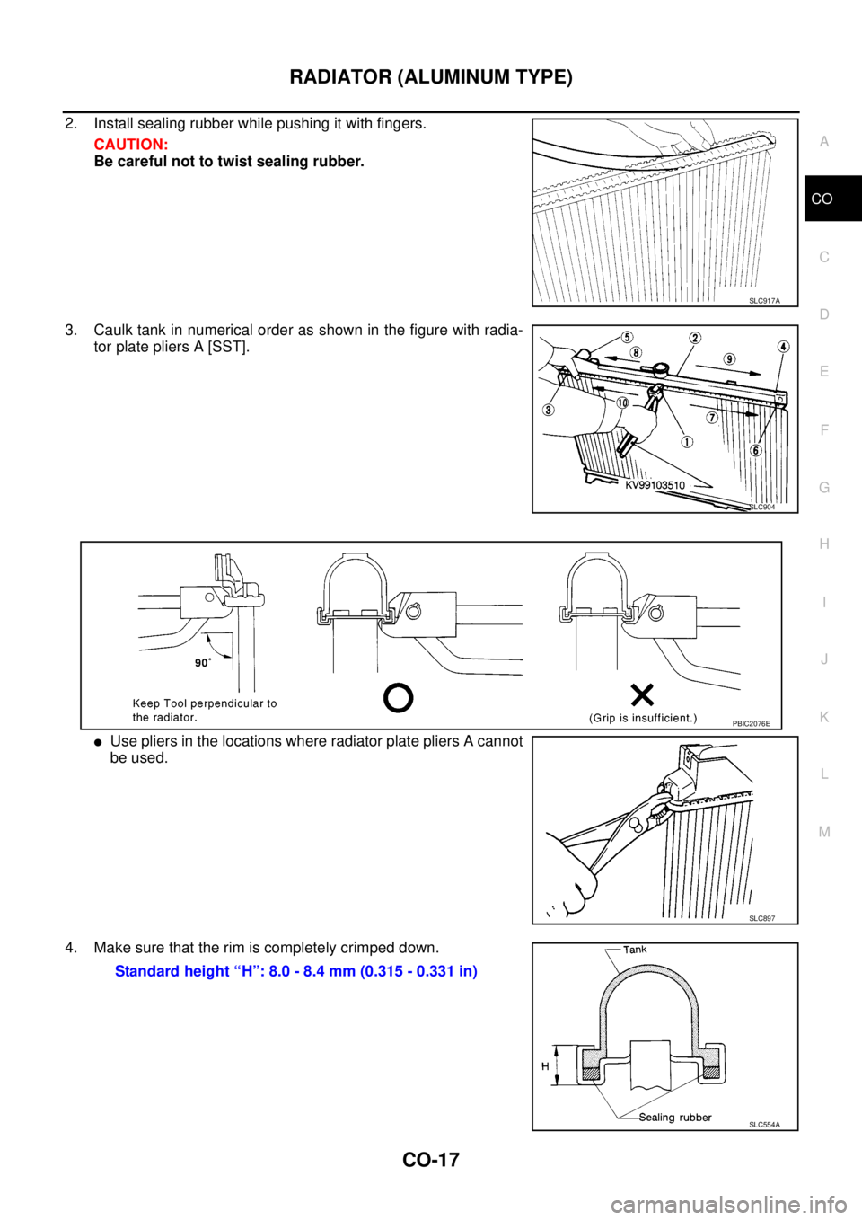
2. Install sealing rubber while pushing it with fingers.
CAUTION:
Be careful not to twist sealing rubber.
3. Caulk tank in numerical order as shown in the figure with radia-
tor plate pliers A [SST].
lUse pliers in the locations where radiator plate pliers A cannot
be used.
4. Make sure that the rim is completely crimped down.
SLC917A
SLC904
PBIC2076E
SLC897
Standard height “H”: 8.0 - 8.4 mm (0.315 - 0.331 in)
SLC554A
Page 902 of 3171
![NISSAN NAVARA 2005 Repair Workshop Manual CO-18
RADIATOR (ALUMINUM TYPE)
5. Make sure that there is no leakage.
Refer toCO-18, "
INSPECTION".
INSPECTION
1. Apply pressure with the radiator cap tester adapter [SST] and
the radiator cap tester NISSAN NAVARA 2005 Repair Workshop Manual CO-18
RADIATOR (ALUMINUM TYPE)
5. Make sure that there is no leakage.
Refer toCO-18, "
INSPECTION".
INSPECTION
1. Apply pressure with the radiator cap tester adapter [SST] and
the radiator cap tester](/img/5/57362/w960_57362-901.png)
CO-18
RADIATOR (ALUMINUM TYPE)
5. Make sure that there is no leakage.
Refer toCO-18, "
INSPECTION".
INSPECTION
1. Apply pressure with the radiator cap tester adapter [SST] and
the radiator cap tester (commercial service tool).
WARNING:
To prevent the risk of hose coming undone while under
pressure, securely fasten it down with hose clamp.
CAUTION:
Attach hose to A/T fluid cooler to seal its inlet and outlet. (A/
T models)
2. Check for leakage by soaking radiator in water container with
the testing pressure applied.Testing pressure
: 157 kPa (1.57 bar, 1.6 kg/cm
2,23psi)
SLC933
SLC934
Page 903 of 3171
COOLING FAN
CO-19
C
D
E
F
G
H
I
J
K
L
MA
CO
COOLING FANPFP:21140
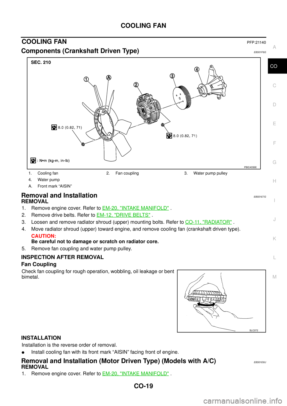
Components (Crankshaft Driven Type)EBS01F6G
Removal and InstallationEBS01E7G
REMOVAL
1. Remove engine cover. Refer toEM-20, "INTAKE MANIFOLD".
2. Remove drive belts. Refer toEM-12, "
DRIVE BELTS".
3. Loosen and remove radiator shroud (upper) mounting bolts. Refer toCO-11, "
RADIATOR".
4. Move radiator shroud (upper) toward engine, and remove cooling fan (crankshaft driven type).
CAUTION:
Be careful not to damage or scratch on radiator core.
5. Remove fan coupling and water pump pulley.
INSPECTION AFTER REMOVAL
Fan Coupling
Check fan coupling for rough operation, wobbling, oil leakage or bent
bimetal.
INSTALLATION
Installation is the reverse order of removal.
lInstall cooling fan with its front mark “AISIN” facing front of engine.
Removal and Installation (Motor Driven Type) (Models with A/C)EBS01E6U
REMOVAL
1. Remove engine cover. Refer toEM-20, "INTAKE MANIFOLD".
1. Cooling fan 2. Fan coupling 3. Water pump pulley
4. Water pump
A. Front mark “AISIN”
PBIC4056E
SLC072
Page 904 of 3171
CO-20
COOLING FAN
2. Disconnect harness connector from fan motor, and move it to aside.
3. Loosen and remove radiator shroud (upper) mounting bolts. Refer toCO-11, "
RADIATOR".
4. Move radiator shroud (upper) toward engine, and remove cooling fan (motor driven type). Refer toCO-11,
"RADIATOR".
CAUTION:
Be careful not to damage or scratch on radiator core.
INSTALLATION
Installation is the reverse order of removal.
lCooling fan (motor driven type) is controlled by ECM. For details, refer toEC-132, "DTC P0217 ENGINE
OVER TEMPERATURE".
Page 905 of 3171
WATER PUMP
CO-21
C
D
E
F
G
H
I
J
K
L
MA
CO
WAT E R P U MPPFP:21020
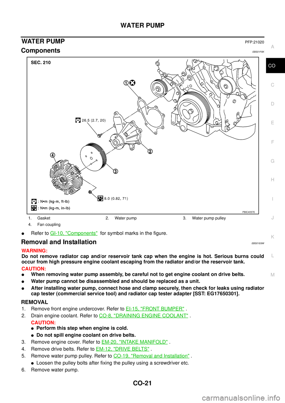
ComponentsEBS01F6K
lRefer toGI-10, "Components"for symbol marks in the figure.
Removal and InstallationEBS01E6W
WARNING:
Do not remove radiator cap and/or reservoir tank cap when the engine is hot. Serious burns could
occur from high pressure engine coolant escaping from the radiator and/or the reservoir tank.
CAUTION:
lWhen removing water pump assembly, be careful not to get engine coolant on drive belts.
lWater pump cannot be disassembled and should be replaced as a unit.
lAfter installing water pump, connect hose and clamp securely, then check for leaks using radiator
cap tester (commercial service tool) and radiator cap tester adapter [SST: EG17650301].
REMOVAL
1. Remove front engine undercover. Refer toEI-15, "FRONT BUMPER".
2. Drain engine coolant. Refer toCO-8, "
DRAINING ENGINE COOLANT".
CAUTION:
lPerform this step when engine is cold.
lDo not spill engine coolant on drive belts.
3. Remove engine cover. Refer toEM-20, "
INTAKE MANIFOLD".
4. Remove drive belts. Refer toEM-12, "
DRIVE BELTS".
5. Remove water pump pulley. Refer toCO-19, "
Removal and Installation".
lLoosen the pulley bolts after fixing the pulley using a screwdriver etc.
6. Remove water pump.
1. Gasket 2. Water pump 3. Water pump pulley
4. Fan coupling
PBIC4057E
Page 906 of 3171
CO-22
WATER PUMP
lEngine coolant will leak from cylinder block, so have a receptacle ready below.
CAUTION:
lHandle the water pump vane so that it does not contact any other parts.
lWater pump cannot be disassembled and should be replaced as a unit.
INSPECTION AFTER REMOVAL
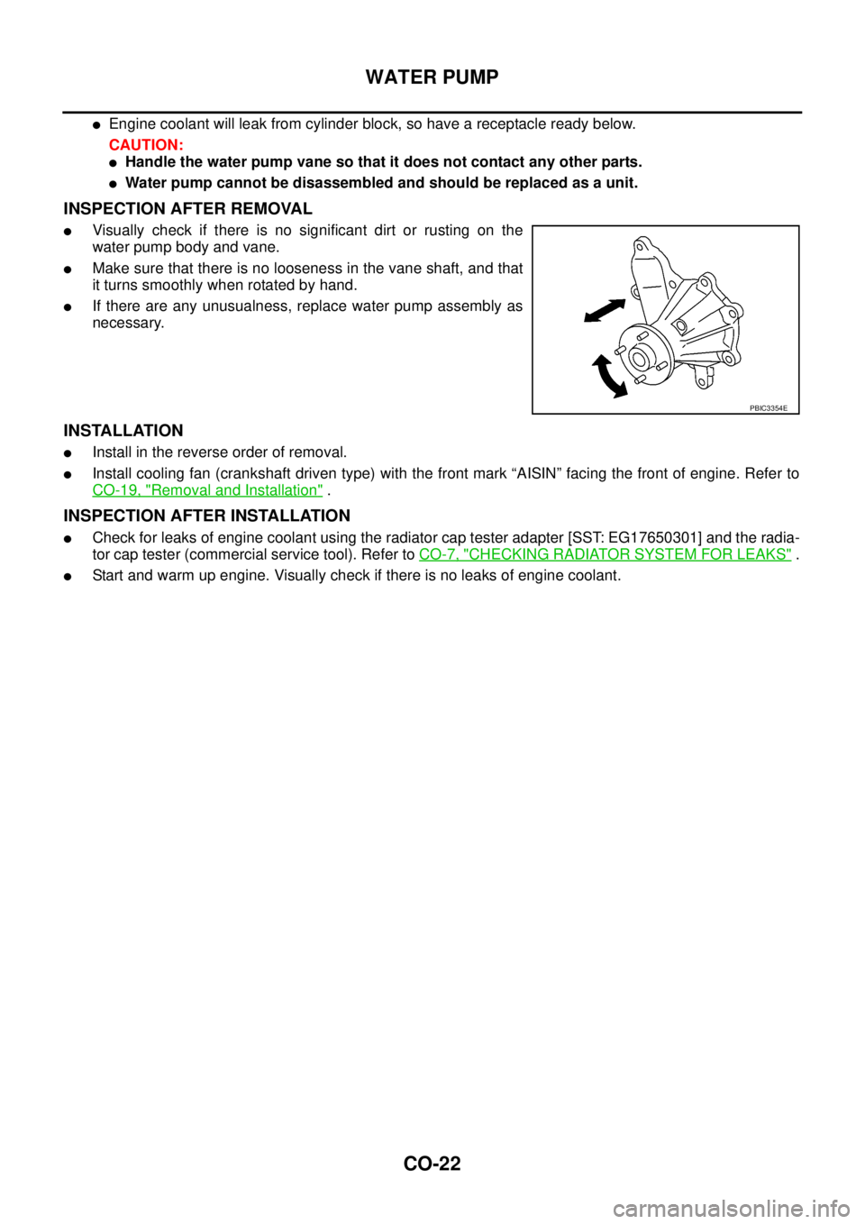
lVisually check if there is no significant dirt or rusting on the
water pump body and vane.
lMake sure that there is no looseness in the vane shaft, and that
it turns smoothly when rotated by hand.
lIf there are any unusualness, replace water pump assembly as
necessary.
INSTALLATION
lInstall in the reverse order of removal.
lInstall cooling fan (crankshaft driven type) with the front mark “AISIN” facing the front of engine. Refer to
CO-19, "
Removal and Installation".
INSPECTION AFTER INSTALLATION
lCheck for leaks of engine coolant using the radiator cap tester adapter [SST: EG17650301] and the radia-
tor cap tester (commercial service tool). Refer toCO-7, "
CHECKING RADIATOR SYSTEM FOR LEAKS".
lStart and warm up engine. Visually check if there is no leaks of engine coolant.
PBIC3354E
Page 907 of 3171
THERMOSTAT AND WATER PIPING
CO-23
C
D
E
F
G
H
I
J
K
L
MA
CO
THERMOSTAT AND WATER PIPINGPFP:21200
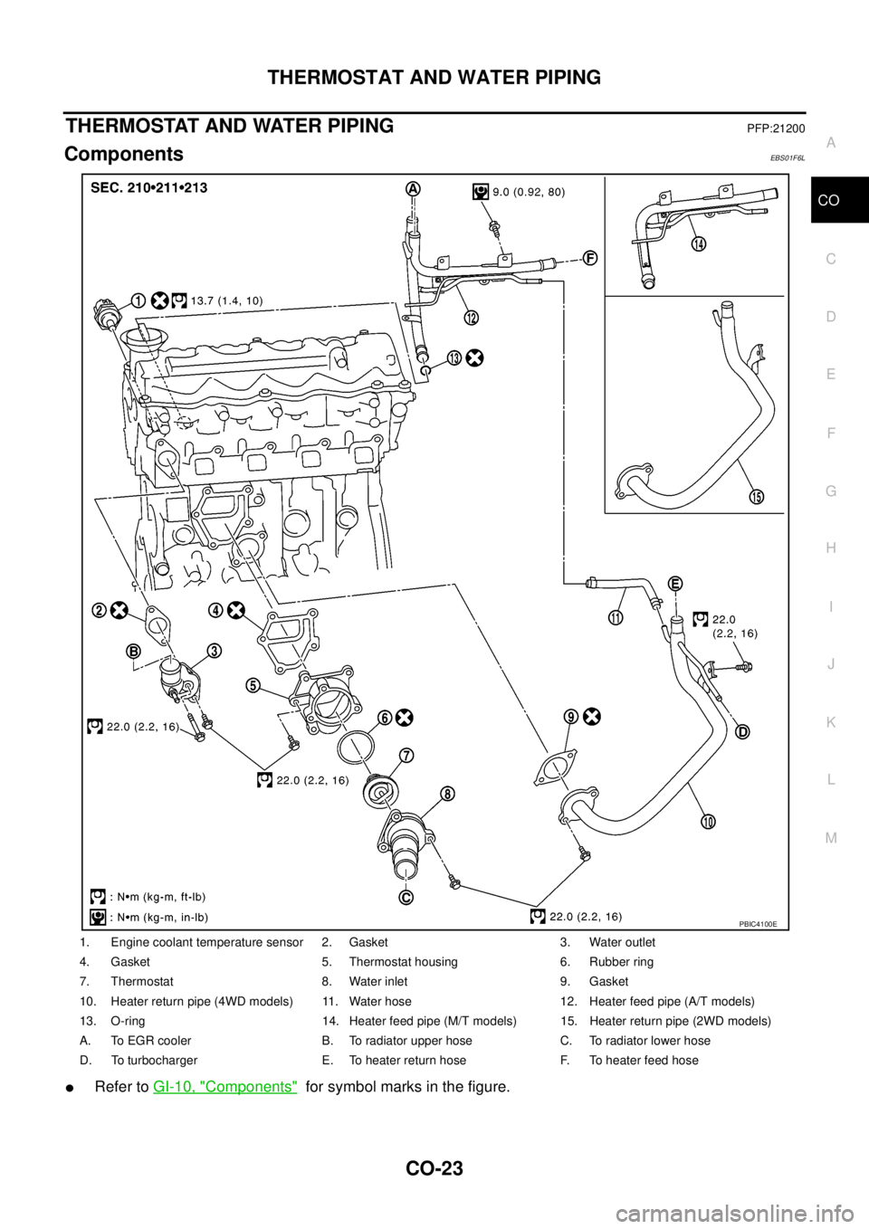
ComponentsEBS01F6L
lRefer toGI-10, "Components"for symbol marks in the figure.
1. Engine coolant temperature sensor 2. Gasket 3. Water outlet
4. Gasket 5. Thermostat housing 6. Rubber ring
7. Thermostat 8. Water inlet 9. Gasket
10. Heater return pipe (4WD models) 11. Water hose 12. Heater feed pipe (A/T models)
13. O-ring 14. Heater feed pipe (M/T models) 15. Heater return pipe (2WD models)
A. To EGR cooler B. To radiator upper hose C. To radiator lower hose
D. To turbocharger E. To heater return hose F. To heater feed hose
PBIC4100E
Page 908 of 3171
CO-24
THERMOSTAT AND WATER PIPING
Removal and Installation
EBS01E6X
WARNING:
Do not remove radiator cap and/or reservoir tank cap when engine is hot. Serious burns could occur
from high pressure engine coolant escaping from radiator and/or reservoir tank.
REMOVAL
1. Remove front engine undercover and middle engine undercover. Refer toEI-15, "FRONT BUMPER".
2. Drain engine coolant from radiator drain plug at the bottom of radiator, and from water drain plug at the
side of cylinder block. Refer toCO-7, "
Changing Engine Coolant"andEM-110, "CYLINDER BLOCK".
CAUTION:
Perform this step when engine is cold.
3. Remove engine cover. Refer toEM-20, "
INTAKE MANIFOLD".
4. Disconnect radiator hoses (upper and lower) from engine side. Refer toCO-11, "
RADIATOR".
5. Remove air inlet pipe and air duct between air cleaner case and turbocharger. Refer toEM-15, "
AIR
CLEANER AND AIR DUCT"andEM-28, "TURBO CHARGER".
6. Remove water outlet, water inlet and thermostat.
7. Remove thermostat housing.
8. Disconnect heater return hose and water hoses at heater return pipe side, and remove heater return pipe.
9. Remove oil level gauge guide mounting bolt, vacuum hoses (to turbocharger boost control solenoid valve)
and spill hose. Refer toEM-36, "
OIL PAN AND OIL STRAINER",EM-20, "INTAKE MANIFOLD"andEM-
44, "INJECTION TUBE AND FUEL INJECTOR".
10. Disconnect water hoses (to EGR cooler) (A/T models), vacuum hoses and heater feed hose at heater
feed pipe side, and remove heater feed pipe. Refer toEM-20, "
INTAKE MANIFOLD".
INSPECTION AFTER REMOVAL
Thermostat
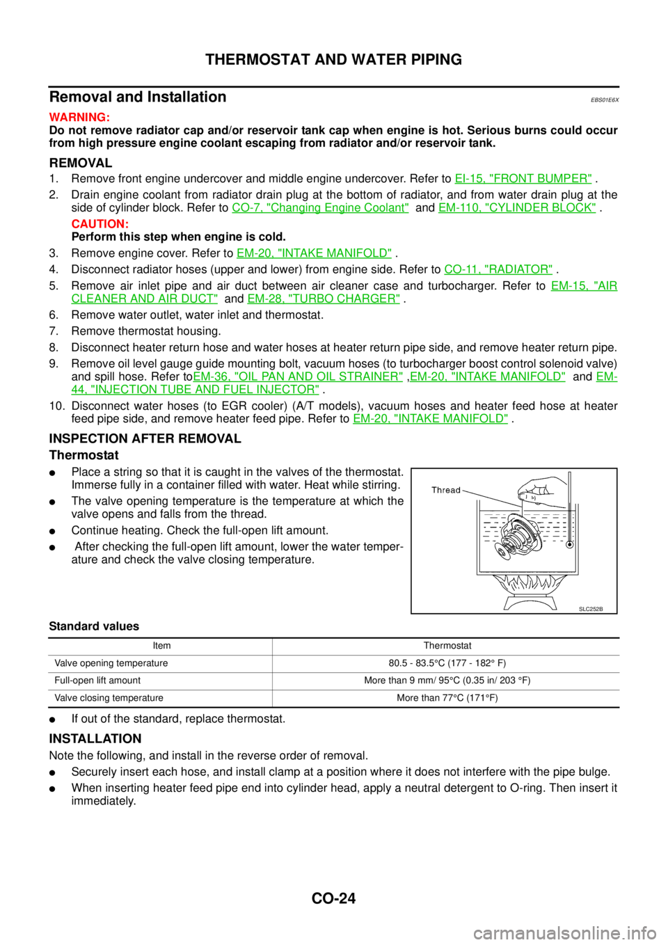
lPlace a string so that it is caught in the valves of the thermostat.
Immerse fully in a container filled with water. Heat while stirring.
lThe valve opening temperature is the temperature at which the
valve opens and falls from the thread.
lContinue heating. Check the full-open lift amount.
lAfter checking the full-open lift amount, lower the water temper-
ature and check the valve closing temperature.
Standard values
lIf out of the standard, replace thermostat.
INSTALLATION
Note the following, and install in the reverse order of removal.
lSecurely insert each hose, and install clamp at a position where it does not interfere with the pipe bulge.
lWhen inserting heater feed pipe end into cylinder head, apply a neutral detergent to O-ring. Then insert it
immediately.
SLC252B
Item Thermostat
Valve opening temperature 80.5 - 83.5°C (177 - 182°F)
Full-open lift amount More than 9 mm/ 95°C (0.35 in/ 203°F)
Valve closing temperature More than 77°C(171°F)
Page 909 of 3171
THERMOSTAT AND WATER PIPING
CO-25
C
D
E
F
G
H
I
J
K
L
MA
CO
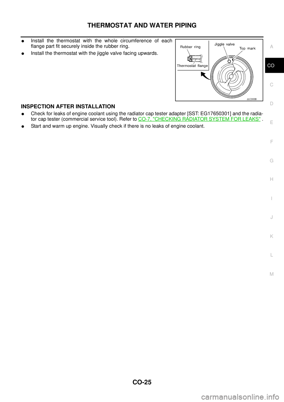
lInstall the thermostat with the whole circumference of each
flange part fit securely inside the rubber ring.
lInstall the thermostat with the jiggle valve facing upwards.
INSPECTION AFTER INSTALLATION
lCheck for leaks of engine coolant using the radiator cap tester adapter [SST: EG17650301] and the radia-
tor cap tester (commercial service tool). Refer toCO-7, "
CHECKING RADIATOR SYSTEM FOR LEAKS".
lStart and warm up engine. Visually check if there is no leaks of engine coolant.
JLC300B
Page 910 of 3171

CO-26
SERVICE DATA AND SPECIFICATIONS (SDS)
SERVICE DATA AND SPECIFICATIONS (SDS)
PFP:00030
Standard and LimitEBS01E6Y
ENGINE COOLANT CAPACITY
Unit: (lmp qt)
THERMOSTAT
RESERVOIR TANK
Unit:kPa(bar,kg/cm2, psi)
Engine coolant capacity
(With reservoir tank at “MAX” level)LHD models Approx. 9.9 (8-3/4)
RHD models Approx. 10.2 (9)
Reservoir tank (at “MAX” level)0.8 (3/4)
Valve opening temperature 80.5 - 83.5°C (177 - 182°F)
Full open lift amount More than 9 mm/ 95°C (0.35 in/203°F)
Valve closing temperature More than 77°C(171°F)
Cap relief pressureStandard 98.2 - 117.8 (0.98 - 1.18, 1.0 - 1.2, 14 - 17)
Limit 59 (0.59, 0.6, 9)
Leakage test pressure 157 (1.57, 1.6, 23)