fuse NISSAN NAVARA 2005 Repair Manual Online
[x] Cancel search | Manufacturer: NISSAN, Model Year: 2005, Model line: NAVARA, Model: NISSAN NAVARA 2005Pages: 3171, PDF Size: 49.59 MB
Page 2096 of 3171
HEADLAMP -CONVENTIONAL TYPE-
LT-13
C
D
E
F
G
H
I
J
L
MA
B
LT
How to Proceed With Trouble DiagnosisEKS00P7O
1. Confirm the symptom or customer complaint.
2. Understand operation description and function description. Refer toLT- 5 , "
System Description".
3. Perform the Preliminary Check. Refer toLT-13, "
Preliminary Check".
4. Check symptom and repair or replace the cause of malfunction.
5. Does the headlamp operate normally? If YES: GO TO 6. If NO: GO TO 4.
6. INSPECTION END
Preliminary CheckEKS00P7P
CHECK POWER SUPPLY AND GROUND CIRCUIT
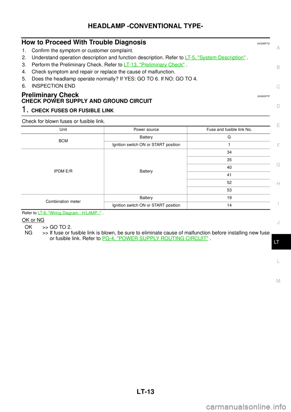
1.CHECK FUSES OR FUSIBLE LINK
Check for blown fuses or fusible link.
Refer toLT- 8 , "Wiring Diagram - H/LAMP -".
OK or NG
OK >> GO TO 2.
NG >> If fuse or fusible link is blown, be sure to eliminate cause of malfunction before installing new fuse
or fusible link. Refer toPG-4, "
POWER SUPPLY ROUTING CIRCUIT".
Unit Power source Fuse and fusible link No.
BCMBattery G
Ignition switch ON or START position 1
IPDM E/R Battery34
35
40
41
52
53
Combination meterBattery 19
Ignition switch ON or START position 14
Page 2115 of 3171

LT-32
HEADLAMP - DAYTIME LIGHT SYSTEM -
OUTLINE
Power is supplied at all times
lto ignition relay (located in IPDM E/R)
lto headlamp high relay (located in IPDM E/R) and
lto headlamp low relay (located in IPDM E/R), from battery directly,
lthrough 50A fusible link (letter G, located in fuse and fusible link box)
lto BCM terminal 57,
lthrough 20A fuse (No. 52, located in IPDM E/R) and
lthrough 20A fuse (No. 53, located in IPDM E/R)
lto CPU (located in IPDM E/R),
lthrough 10A fuse [No. 19, located in fuse block (J/B)]
lto combination meter terminal 3.
With the ignition switch in the ON or START position, power is supplied
lto ignition relay (located in IPDM E/R),
lthrough 10A fuse [No. 1, located in fuse block (J/B)]
lto BCM terminal 3,
lthrough 10A fuse [No. 14, located in fuse block (J/B)]
lto combination meter terminal 16.
Ground is supplied at all times
lto BCM terminal 55 and
lto combination meter terminal 23
lthrough grounds M21, M80 and M83,
lto IPDM E/R terminals 38 and 59
lthrough grounds E21, E41 and E61.
DAYTIME LIGHT OPERATION
With the lighting switch in the OFF position and engine running, the BCM receives input signal requesting
headlamp low beam, clearance lamp, license plate lamp, and tail lamp to illuminate. This input signal is com-
municated to the IPDM E/R through the CAN communication. The CPU located in the IPDM E/R controls
headlamp low relay.
lthrough 15A fuse (No. 41, located in IPDM E/R)
lthrough IPDM E/R terminal 54
lto front combination lamp RH terminal 1,
lthrough 15A fuse (No. 40, located in IPDM E/R)
lthrough IPDM E/R terminal 52
lto front combination lamp LH terminal 1.
Ground is supplied at all times
lto front combination lamp RH and LH terminals 3
lthrough grounds E21, E41 and E61.
With power and ground supplied, the headlamp low beam, clearance, license plate and tail lamps illuminate.
Page 2123 of 3171
LT-40
HEADLAMP - DAYTIME LIGHT SYSTEM -
How to Proceed With Trouble Diagnosis
EKS00Q7M
1. Confirm the symptom or customer complaint.
2. Understand operation description and function description. Refer toLT-31, "
System Description".
3. Perform the Preliminary Check. Refer toLT-40, "
Preliminary Check".
4. Check symptom and repair or replace the cause of malfunction.
5. Does the headlamp operate normally? If YES, GO TO 6. If NO, GO TO 4.
6. INSPECTION END
Preliminary CheckEKS00Q7N
CHECK POWER SUPPLY AND GROUND CIRCUIT
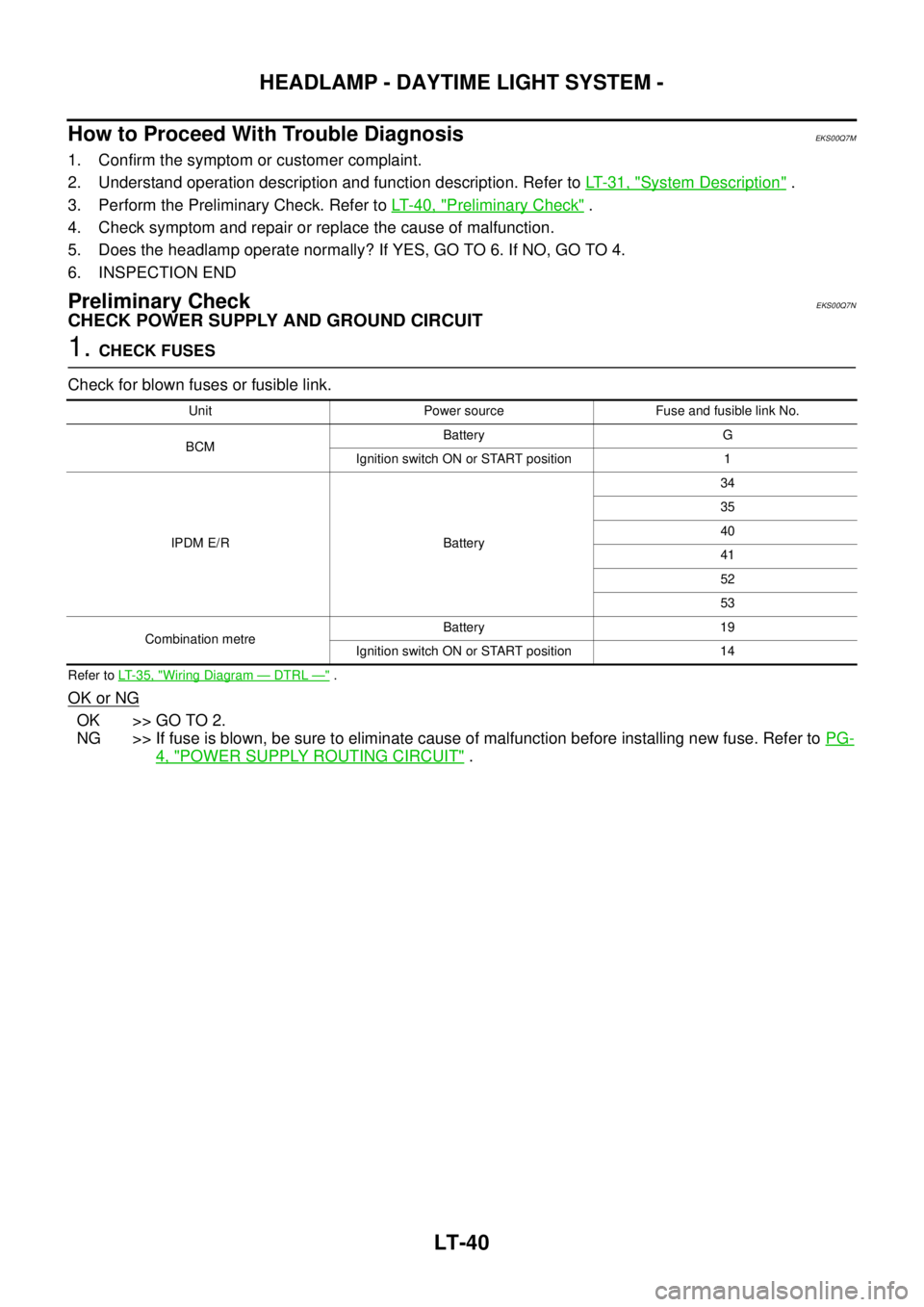
1.CHECK FUSES
Check for blown fuses or fusible link.
Refer toLT-35, "Wiring Diagram—DTRL—".
OK or NG
OK >> GO TO 2.
NG >> If fuse is blown, be sure to eliminate cause of malfunction before installing new fuse. Refer toPG-
4, "POWER SUPPLY ROUTING CIRCUIT".
Unit Power source Fuse and fusible link No.
BCMBattery G
Ignition switch ON or START position 1
IPDM E/R Battery34
35
40
41
52
53
Combination metreBattery 19
Ignition switch ON or START position 14
Page 2141 of 3171
LT-58
AUTO LIGHT SYSTEM
Preliminary Check
EKS00Q84
SETTING CHANGE FUNCTIONS
lSensitivity of auto light system can be adjusted using CONSULT-II. Refer toLT-60, "WORK SUPPORT".
CHECK POWER SUPPLY AND GROUND CIRCUIT
1.CHECK FUSES OR FUSIBLE LINK
Check for blown fuses or fusible link.
*1: Without daytime light system, *2: With daytime light system
Refer toLT-52, "
Wiring Diagram—AUTO/L—".
OK or NG
OK >> GO TO 2.
NG >> If fuse or fusible link is blown, be sure to eliminate cause of malfunction before installing new fuse
or fusible link. Refer toPG-4, "
POWER SUPPLY ROUTING CIRCUIT".
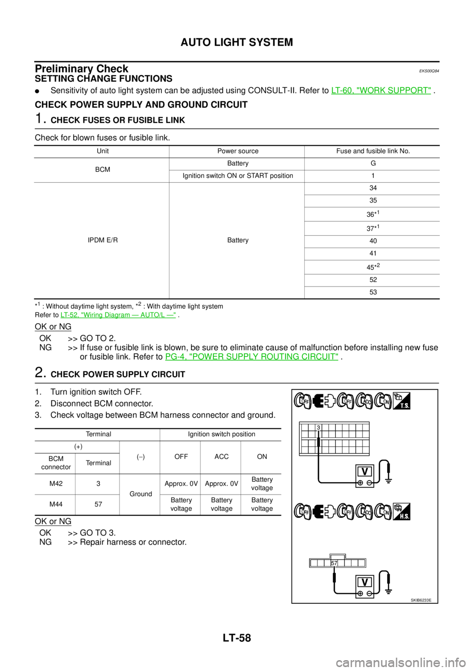
2.CHECK POWER SUPPLY CIRCUIT
1. Turn ignition switch OFF.
2. Disconnect BCM connector.
3. Check voltage between BCM harness connector and ground.
OK or NG
OK >> GO TO 3.
NG >> Repair harness or connector.
Unit Power source Fuse and fusible link No.
BCMBattery G
Ignition switch ON or START position 1
IPDM E/R Battery34
35
36*
1
37*1
40
41
45*
2
52
53
Terminal Ignition switch position
(+)
(-)OFFACCON
BCM
connectorTerminal
M42 3
GroundApprox. 0V Approx. 0VBattery
voltage
M44 57Battery
voltageBattery
voltageBattery
voltage
SKIB6233E
Page 2154 of 3171
FRONT FOG LAMP
LT-71
C
D
E
F
G
H
I
J
L
MA
B
LT
FRONT FOG LAMPPFP:26150
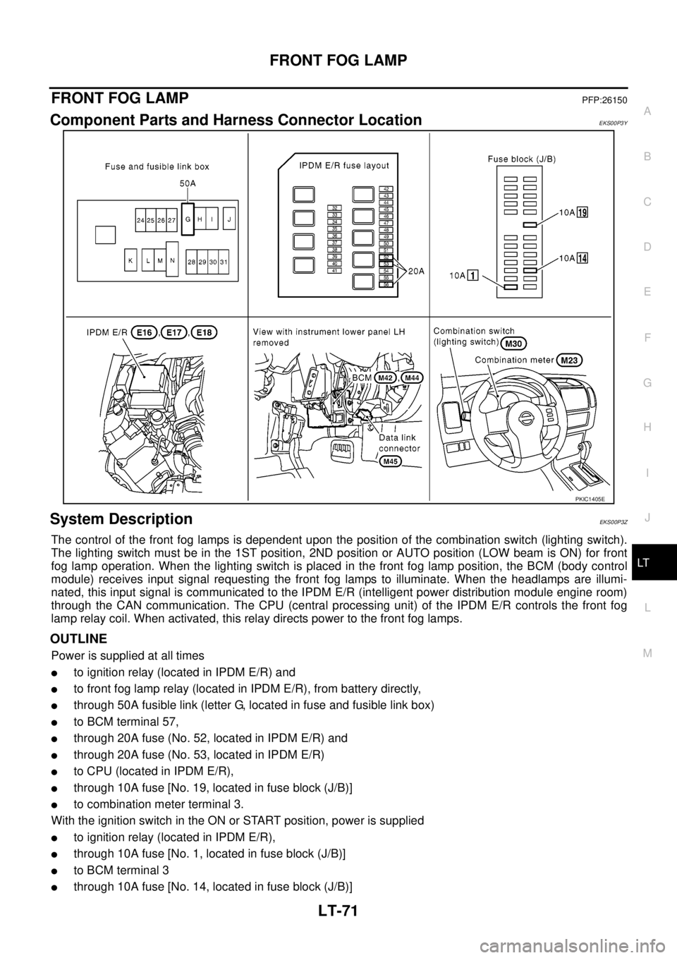
Component Parts and Harness Connector LocationEKS00P3Y
System DescriptionEKS00P3Z
The control of the front fog lamps is dependent upon the position of the combination switch (lighting switch).
The lighting switch must be in the 1ST position, 2ND position or AUTO position (LOW beam is ON) for front
fog lamp operation. When the lighting switch is placed in the front fog lamp position, the BCM (body control
module) receives input signal requesting the front fog lamps to illuminate. When the headlamps are illumi-
nated, this input signal is communicated to the IPDM E/R (intelligent power distribution module engine room)
through the CAN communication. The CPU (central processing unit) of the IPDM E/R controls the front fog
lamp relay coil. When activated, this relay directs power to the front fog lamps.
OUTLINE
Power is supplied at all times
lto ignition relay (located in IPDM E/R) and
lto front fog lamp relay (located in IPDM E/R), from battery directly,
lthrough 50A fusible link (letter G, located in fuse and fusible link box)
lto BCM terminal 57,
lthrough 20A fuse (No. 52, located in IPDM E/R) and
lthrough 20A fuse (No. 53, located in IPDM E/R)
lto CPU (located in IPDM E/R),
lthrough 10A fuse [No. 19, located in fuse block (J/B)]
lto combination meter terminal 3.
With the ignition switch in the ON or START position, power is supplied
lto ignition relay (located in IPDM E/R),
lthrough 10A fuse [No. 1, located in fuse block (J/B)]
lto BCM terminal 3
lthrough 10A fuse [No. 14, located in fuse block (J/B)]
PKIC1405E
Page 2155 of 3171

LT-72
FRONT FOG LAMP
lto combination meter terminal 16.
Ground is supplied
lto BCM terminal 55 and
lto combination meter terminal 23
lthrough grounds M21, M80 and M83,
lto IPDM E/R terminals 38 and 59
lthrough grounds E21, E41 and E61.
FOG LAMP OPERATION
The front fog lamp switch is built into the combination switch. The lighting switch must be in the 1ST position,
2ND position or AUTO position (LOW beam is ON) and the front fog lamp switch must be ON for front fog lamp
operation.
With the front fog lamp switch in the ON position, the CPU of the IPDM E/R grounds the coil side of the front
fog lamp relay. The front fog lamp relay then directs power
lthrough 20A fuse (No. 56, located in IPDM E/R)
lthrough IPDM E/R terminal 50
lto front fog lamp LH terminal 1 and
lthrough IPDM E/R terminal 51
lto front fog lamp RH terminal 1.
Ground is supplied at all times
lto front fog lamp RH and LH terminal 2
lthrough grounds E21, E41 and E61.
With power and ground supplied, the front fog lamps illuminate.
COMBINATION SWITCH READING FUNCTION
Refer toBCS-3, "COMBINATION SWITCH READING FUNCTION".
CAN Communication System DescriptionEKS00P40
Refer toLAN-23, "CAN COMMUNICATION".
Page 2161 of 3171
LT-78
FRONT FOG LAMP
How to Proceed With Trouble Diagnosis
EKS00P45
1. Confirm the symptom or customer complaint.
2. Understand operation description and function description. Refer toLT-71, "
System Description".
3. Perform the Preliminary Check. Refer toLT-78, "
Preliminary Check".
4. Check symptom and repair or replace the cause of malfunction.
5. Does the front fog lamp operate normally? If YES: GO TO 6. If NO: GO TO 4.
6. INSPECTION END
Preliminary CheckEKS00P46
CHECK POWER SUPPLY AND GROUND CIRCUIT
1.CHECK FUSES OR FUSIBLE LINK
Check for blown fuses or fusible link.
Refer toLT-74, "Wiring Diagram—F/FOG—".
OK or NG
OK >> GO TO 2.
NG >> If fuse or fusible link is blown, be sure to eliminate cause of malfunction before installing new fuse
or fusible link. Refer toPG-4, "
POWER SUPPLY ROUTING CIRCUIT".
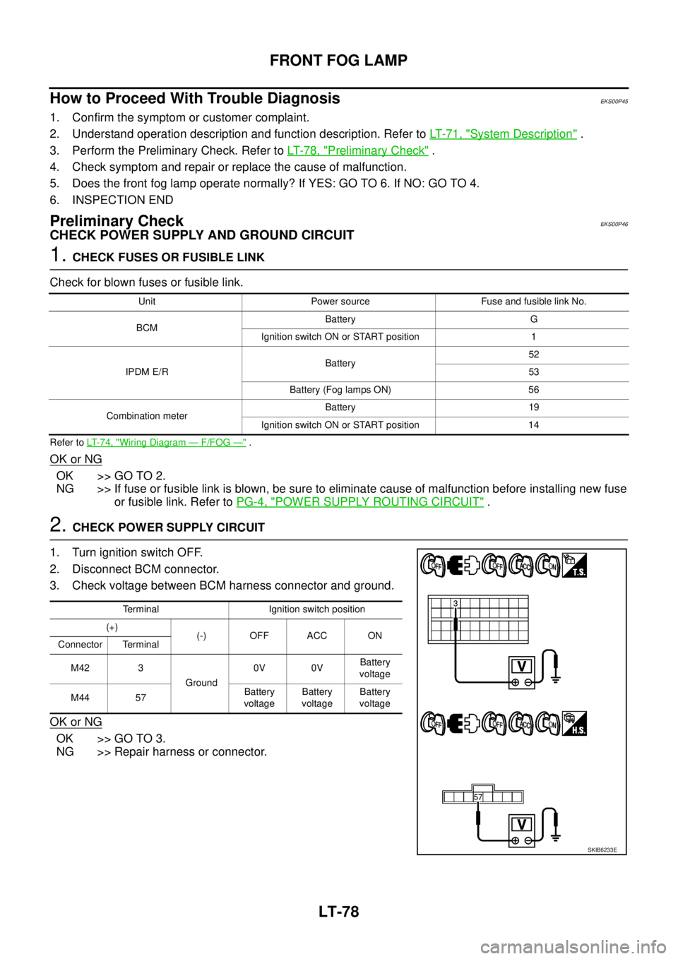
2.CHECK POWER SUPPLY CIRCUIT
1. Turn ignition switch OFF.
2. Disconnect BCM connector.
3. Check voltage between BCM harness connector and ground.
OK or NG
OK >> GO TO 3.
NG >> Repair harness or connector.
Unit Power source Fuse and fusible link No.
BCMBattery G
Ignition switch ON or START position 1
IPDM E/RBattery52
53
Battery (Fog lamps ON) 56
Combination meterBattery 19
Ignition switch ON or START position 14
Terminal Ignition switch position
(+)
(-) OFF ACC ON
Connector Terminal
M42 3
Ground0V 0VBattery
voltage
M44 57Battery
voltageBattery
voltageBattery
voltage
SKIB6233E
Page 2170 of 3171
REAR FOG LAMP
LT-87
C
D
E
F
G
H
I
J
L
MA
B
LT
REAR FOG LAMPPFP:26550
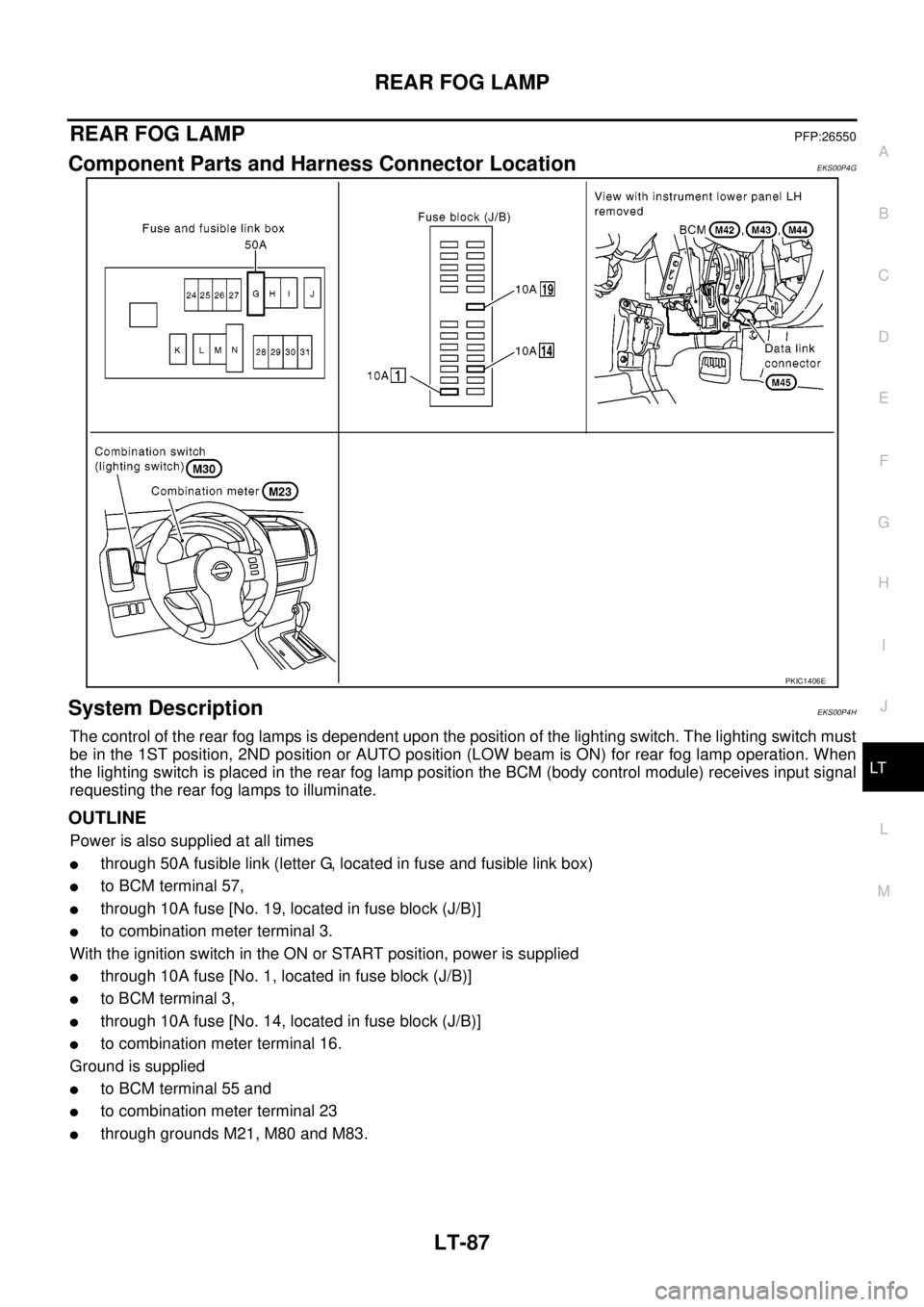
Component Parts and Harness Connector LocationEKS00P4G
System DescriptionEKS00P4H
The control of the rear fog lamps is dependent upon the position of the lighting switch. The lighting switch must
be in the 1ST position, 2ND position or AUTO position (LOW beam is ON) for rear fog lamp operation. When
the lighting switch is placed in the rear fog lamp position the BCM (body control module) receives input signal
requesting the rear fog lamps to illuminate.
OUTLINE
Power is also supplied at all times
lthrough 50A fusible link (letter G, located in fuse and fusible link box)
lto BCM terminal 57,
lthrough 10A fuse [No. 19, located in fuse block (J/B)]
lto combination meter terminal 3.
With the ignition switch in the ON or START position, power is supplied
lthrough 10A fuse [No. 1, located in fuse block (J/B)]
lto BCM terminal 3,
lthrough 10A fuse [No. 14, located in fuse block (J/B)]
lto combination meter terminal 16.
Ground is supplied
lto BCM terminal 55 and
lto combination meter terminal 23
lthrough grounds M21, M80 and M83.
PKIC1406E
Page 2175 of 3171
LT-92
REAR FOG LAMP
Preliminary Check
EKS00P4N
CHECK POWER SUPPLY AND GROUND CIRCUIT
1.CHECK FUSES
Check for blown fuses.
Refer toLT-89, "Wiring Diagram—R/FOG—".
OK or NG
OK >> GO TO 2.
NO >> If fuse or fusible link is blown, be sure to eliminate cause of malfunction before installing new fuse
or fusible link. Refer toPG-4, "
POWER SUPPLY ROUTING CIRCUIT".
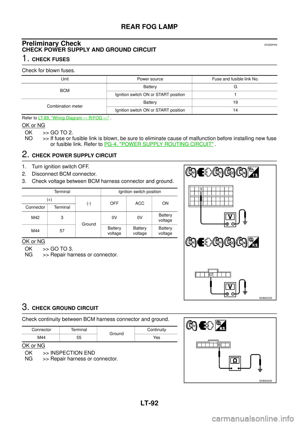
2.CHECK POWER SUPPLY CIRCUIT
1. Turn ignition switch OFF.
2. Disconnect BCM connector.
3. Check voltage between BCM harness connector and ground.
OK or NG
OK >> GO TO 3.
NG >> Repair harness or connector.
3.CHECK GROUND CIRCUIT
Check continuity between BCM harness connector and ground.
OK or NG
OK >> INSPECTION END
NG >> Repair harness or connector.
Unit Power source Fuse and fusible link No.
BCMBattery G
Ignition switch ON or START position 1
Combination meterBattery 19
Ignition switch ON or START position 14
Terminal Ignition switch position
(+)
(-) OFF ACC ON
Connector Terminal
M42 3
Ground0V 0VBattery
voltage
M44 57Battery
voltageBattery
voltageBattery
voltage
SKIB6233E
Connector Terminal
GroundContinuity
M44 55 Yes
SKIB6293E
Page 2180 of 3171
TURN SIGNAL AND HAZARD WARNING LAMPS
LT-97
C
D
E
F
G
H
I
J
L
MA
B
LT
TURN SIGNAL AND HAZARD WARNING LAMPSPFP:26120
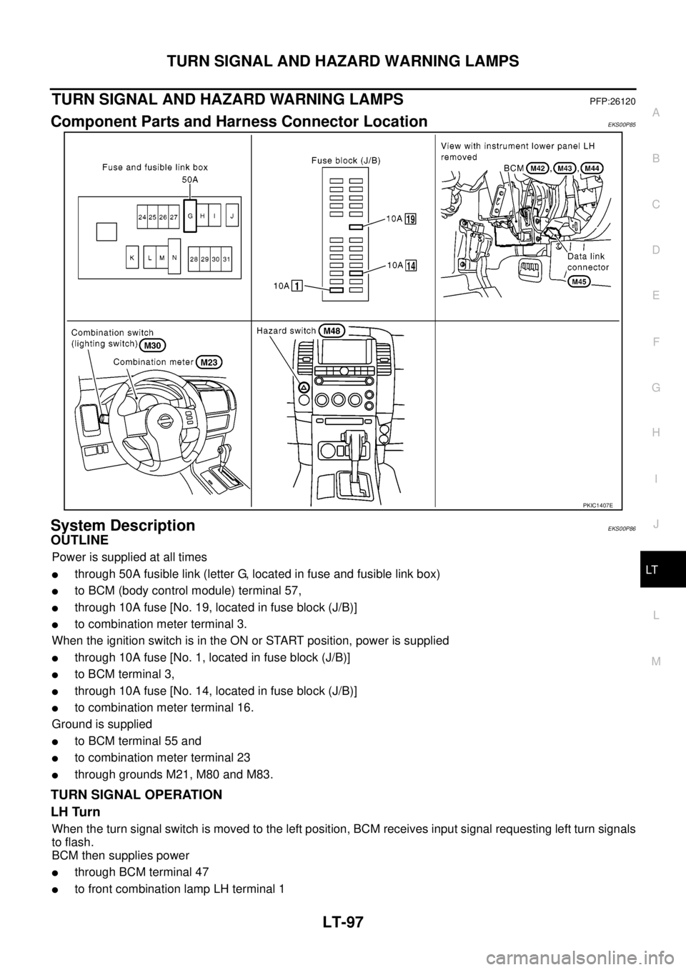
Component Parts and Harness Connector LocationEKS00P85
System DescriptionEKS00P86
OUTLINE
Power is supplied at all times
lthrough 50A fusible link (letter G, located in fuse and fusible link box)
lto BCM (body control module) terminal 57,
lthrough 10A fuse [No. 19, located in fuse block (J/B)]
lto combination meter terminal 3.
When the ignition switch is in the ON or START position, power is supplied
lthrough 10A fuse [No. 1, located in fuse block (J/B)]
lto BCM terminal 3,
lthrough 10A fuse [No. 14, located in fuse block (J/B)]
lto combination meter terminal 16.
Ground is supplied
lto BCM terminal 55 and
lto combination meter terminal 23
lthrough grounds M21, M80 and M83.
TURN SIGNAL OPERATION
LH Turn
When the turn signal switch is moved to the left position, BCM receives input signal requesting left turn signals
to flash.
BCM then supplies power
lthrough BCM terminal 47
lto front combination lamp LH terminal 1
PKIC1407E