NISSAN NAVARA 2005 Repair Workshop Manual
Manufacturer: NISSAN, Model Year: 2005, Model line: NAVARA, Model: NISSAN NAVARA 2005Pages: 3171, PDF Size: 49.59 MB
Page 971 of 3171
WARNING CHIME
DI-61
C
D
E
F
G
H
I
J
L
MA
B
DI
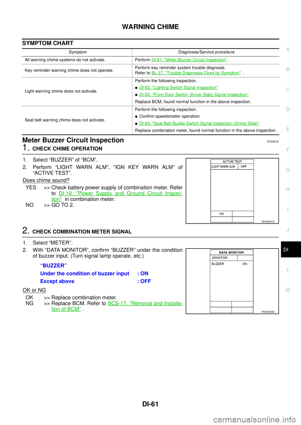
SYMPTOM CHART
Meter Buzzer Circuit InspectionEKS00L9L
1.CHECK CHIME OPERATION
1. Select “BUZZER” of “BCM”.
2. Perform “LIGHT WARN ALM”, “IGN KEY WARN ALM” of
“ACTIVE TEST”.
Does chime sound?
YES >> Check battery power supply of combination meter. Refer
toDI-19, "
Power Supply and Ground Circuit Inspec-
tion"in combination meter.
NO >> GO TO 2.
2.CHECK COMBINATION METER SIGNAL
1. Select “METER”.
2. With “DATA MONITOR”, confirm “BUZZER” under the condition
of buzzer input. (Turn signal lamp operate, etc.)
OK or NG
OK >> Replace combination meter.
NG >> Replace BCM. Refer toBCS-17, "
Removal and Installa-
tion of BCM".
Symptom Diagnoses/Service procedure
All warning chime systems do not activate. PerformDI-61, "
Meter Buzzer Circuit Inspection".
Key reminder warning chime does not operate.Perform key reminder system trouble diagnosis.
Refer toBL-37, "
Trouble Diagnoses Chart by Symptom".
Light warning chime does not activate.Perform the following inspection.
lDI-62, "Lighting Switch Signal Inspection"
lDI-62, "Front Door Switch (Driver Side) Signal Inspection"
Replace BCM, found normal function in the above inspection.
Seat belt warning chime does not activate.Perform the following inspection.
lConfirm speedometer operation
lDI-63, "Seat Belt Buckle Switch Signal Inspection (Driver Side)"
Replace combination meter, found normal function in the above inspection.
SKIA6331E
“BUZZER”
Under the condition of buzzer input : ON
Except above : OFF
PKIA2063E
Page 972 of 3171
DI-62
WARNING CHIME
Lighting Switch Signal Inspection
EKS00L9O
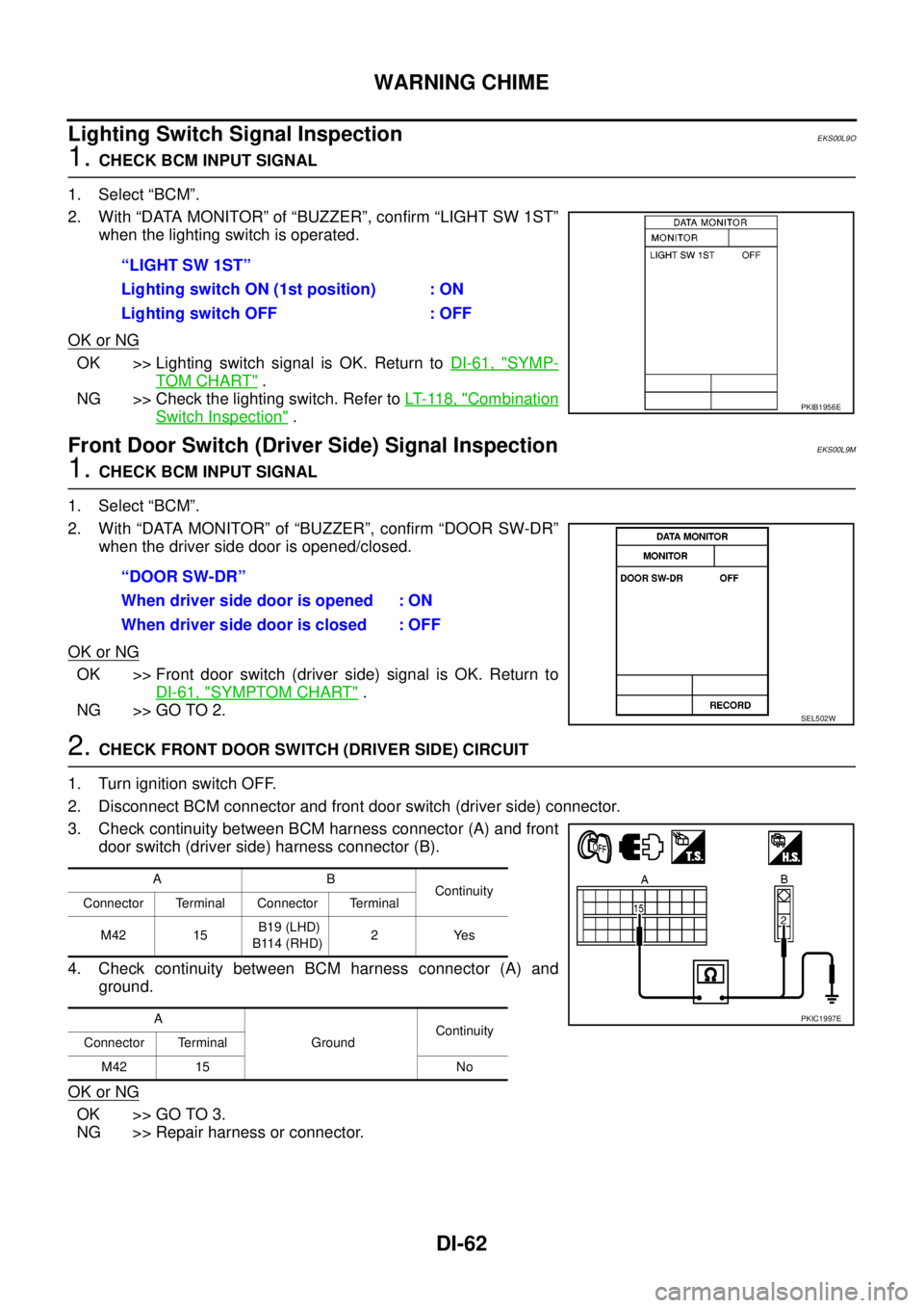
1.CHECK BCM INPUT SIGNAL
1. Select “BCM”.
2. With “DATA MONITOR” of “BUZZER”, confirm “LIGHT SW 1ST”
whenthelightingswitchisoperated.
OK or NG
OK >> Lighting switch signal is OK. Return toDI-61, "SYMP-
TOM CHART".
NG >> Check the lighting switch. Refer toLT- 11 8 , "
Combination
Switch Inspection".
Front Door Switch (Driver Side) Signal InspectionEKS00L9M
1.CHECK BCM INPUT SIGNAL
1. Select “BCM”.
2. With “DATA MONITOR” of “BUZZER”, confirm “DOOR SW-DR”
when the driver side door is opened/closed.
OK or NG
OK >> Front door switch (driver side) signal is OK. Return to
DI-61, "
SYMPTOM CHART".
NG >> GO TO 2.
2.CHECK FRONT DOOR SWITCH (DRIVER SIDE) CIRCUIT
1. Turn ignition switch OFF.
2. Disconnect BCM connector and front door switch (driver side) connector.
3. Check continuity between BCM harness connector (A) and front
door switch (driver side) harness connector (B).
4. Check continuity between BCM harness connector (A) and
ground.
OK or NG
OK >> GO TO 3.
NG >> Repair harness or connector.“LIGHT SW 1ST”
Lighting switch ON (1st position) : ON
Lighting switch OFF : OFF
PKIB1956E
“DOOR SW-DR”
When driver side door is opened : ON
When driver side door is closed : OFF
SEL502W
AB
Continuity
Connector Terminal Connector Terminal
M42 15B19 (LHD)
B114 (RHD)2Yes
A
GroundContinuity
Connector Terminal
M42 15 No
PKIC1997E
Page 973 of 3171
WARNING CHIME
DI-63
C
D
E
F
G
H
I
J
L
MA
B
DI
3.CHECK FRONT DOOR SWITCH (DRIVER SIDE)
Check front door switch (driver side). Refer toDI-64, "
FRONT DOOR SWITCH (DRIVER SIDE)".
OK or NG
OK >> Replace BCM. Refer toBCS-17, "Removal and Installation of BCM".
NG >> Replace front door switch (driver side).
Seat Belt Buckle Switch Signal Inspection (Driver Side)EKS00L9P
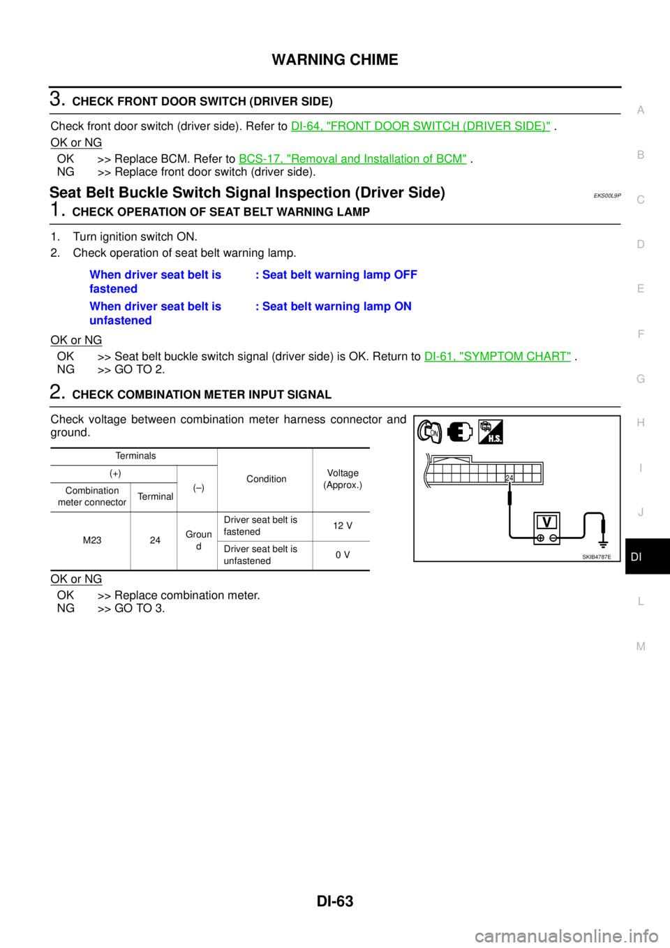
1.CHECK OPERATION OF SEAT BELT WARNING LAMP
1. Turn ignition switch ON.
2. Check operation of seat belt warning lamp.
OK or NG
OK >> Seat belt buckle switch signal (driver side) is OK. Return toDI-61, "SYMPTOM CHART".
NG >> GO TO 2.
2.CHECK COMBINATION METER INPUT SIGNAL
Check voltage between combination meter harness connector and
ground.
OK or NG
OK >> Replace combination meter.
NG >> GO TO 3.When driver seat belt is
fastened: Seat belt warning lamp OFF
When driver seat belt is
unfastened: Seat belt warning lamp ON
Terminals
ConditionVoltag e
(Approx.) (+)
(–)
Combination
meter connectorTerminal
M23 24Groun
dDriver seat belt is
fastened12 V
Driver seat belt is
unfastened0V
SKIB4787E
Page 974 of 3171
DI-64
WARNING CHIME
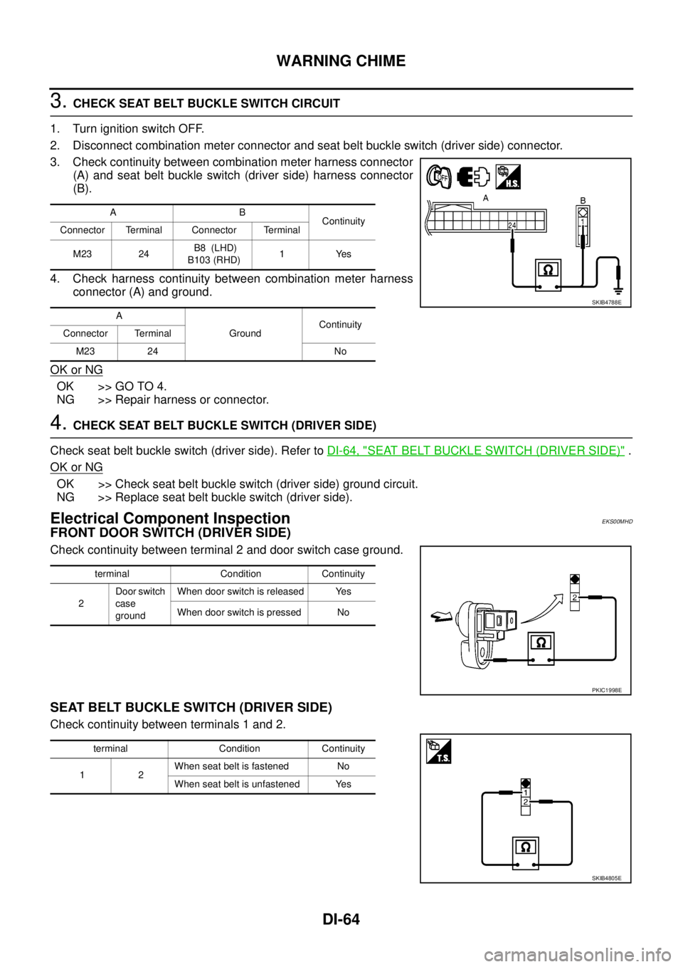
3.CHECK SEAT BELT BUCKLE SWITCH CIRCUIT
1. Turn ignition switch OFF.
2. Disconnect combination meter connector and seat belt buckle switch (driver side) connector.
3. Check continuity between combination meter harness connector
(A) and seat belt buckle switch (driver side) harness connector
(B).
4. Check harness continuity between combination meter harness
connector (A) and ground.
OK or NG
OK >> GO TO 4.
NG >> Repair harness or connector.
4.CHECK SEAT BELT BUCKLE SWITCH (DRIVER SIDE)
Check seat belt buckle switch (driver side). Refer toDI-64, "
SEAT BELT BUCKLE SWITCH (DRIVER SIDE)".
OK or NG
OK >> Check seat belt buckle switch (driver side) ground circuit.
NG >> Replace seat belt buckle switch (driver side).
Electrical Component InspectionEKS00MHD
FRONT DOOR SWITCH (DRIVER SIDE)
Check continuity between terminal 2 and door switch case ground.
SEAT BELT BUCKLE SWITCH (DRIVER SIDE)
Check continuity between terminals 1 and 2.
AB
Continuity
Connector Terminal Connector Terminal
M23 24B8 (LHD)
B103 (RHD)1Yes
A
GroundContinuity
Connector Terminal
M23 24 No
SKIB4788E
terminal Condition Continuity
2Door switch
case
groundWhen door switch is released Yes
When door switch is pressed No
PKIC1998E
terminal Condition Continuity
12When seat belt is fastened No
When seat belt is unfastened Yes
SKIB4805E
Page 975 of 3171
CAN COMMUNICATION
DI-65
C
D
E
F
G
H
I
J
L
MA
B
DI
CAN COMMUNICATIONPFP:23710
System DescriptionEKS00MHE
CAN (Controller Area Network) is a serial communication line for real time application. It is an on-vehicle mul-
tiplex communication line with high data communication speed and excellent error detection ability. Many elec-
tronic control units are equipped onto a vehicle, and each control unit shares information and links with other
control units during operation (not independent). In CAN communication, control units are connected with 2
communication lines (CAN H line, CAN L line) allowing a high rate of information transmission with less wiring.
Each control unit transmits/receives data but selectively reads required data only.
CAN Communication UnitEKS00MHF
Refer toLAN-30, "CAN Communication Unit"in “LAN SYSTEM”.
Page 976 of 3171
DI-66
COMPASS
COMPASS
PFP:24835
System DescriptionEKS00M4Z
This unit displays earth magnetism and heading direction of vehicle.
DIRECTION DISPLAY
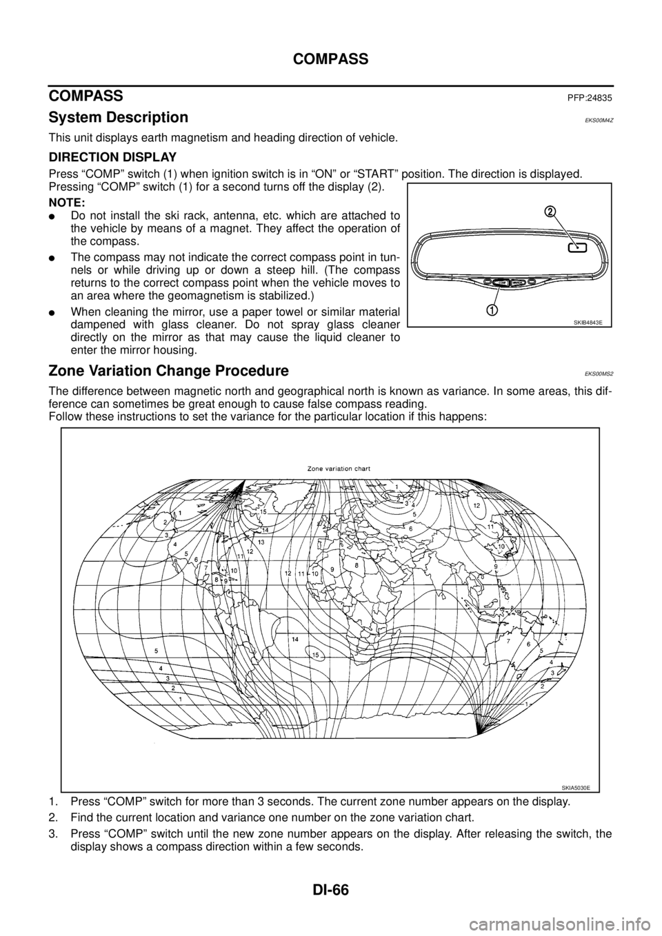
Press “COMP” switch (1) when ignition switch is in “ON” or “START” position. The direction is displayed.
Pressing “COMP” switch (1) for a second turns off the display (2).
NOTE:
lDo not install the ski rack, antenna, etc. which are attached to
the vehicle by means of a magnet. They affect the operation of
the compass.
lThe compass may not indicate the correct compass point in tun-
nels or while driving up or down a steep hill. (The compass
returns to the correct compass point when the vehicle moves to
an area where the geomagnetism is stabilized.)
lWhen cleaning the mirror, use a paper towel or similar material
dampened with glass cleaner. Do not spray glass cleaner
directly on the mirror as that may cause the liquid cleaner to
enter the mirror housing.
Zone Variation Change ProcedureEKS00MS2
The difference between magnetic north and geographical north is known as variance. In some areas, this dif-
ference can sometimes be great enough to cause false compass reading.
Follow these instructions to set the variance for the particular location if this happens:
1. Press “COMP” switch for more than 3 seconds. The current zone number appears on the display.
2. Find the current location and variance one number on the zone variation chart.
3. Press “COMP” switch until the new zone number appears on the display. After releasing the switch, the
display shows a compass direction within a few seconds.
SKIB4843E
SKIA5030E
Page 977 of 3171

COMPASS
DI-67
C
D
E
F
G
H
I
J
L
MA
B
DI
Correction Functions of the Compass DisplayEKS00MS3
AUTOMATIC CORRECTION
The compass display is equipped with automatic correction function. If the direction is not shown correctly,
perform manual correction procedure set out below.
MANUAL CORRECTION PROCEDURE
When the display reads “C” or “CAL”, calibrate the compass by driving the vehicle in 3 complete circles at less
than8km/h(5MPH).
The compass can be calibrated by driving the vehicle on everyday route. The compass is calibrated once it
has tracked 3 complete circles.
In places where the terrestrial magnetism is extremely disturbed, the initial correction procedure may start
automatically.
Page 978 of 3171
DI-68
COMPASS
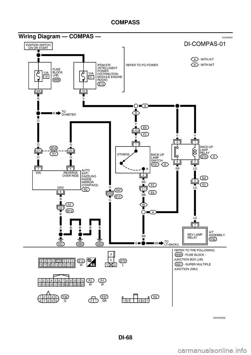
Wiring Diagram — COMPAS —
EKS00M50
MKWA3656E
Page 979 of 3171
COMPASS
DI-69
C
D
E
F
G
H
I
J
L
MA
B
DI
Removal and Installation of CompassEKS00M51
Refer toGW-46, "Removal and Installation".
Page 980 of 3171

DI-70
COMPASS