NISSAN NAVARA 2005 Repair Workshop Manual
NAVARA 2005
NISSAN
NISSAN
https://www.carmanualsonline.info/img/5/57362/w960_57362-0.png
NISSAN NAVARA 2005 Repair Workshop Manual
Trending: engine oil, ABS, fuse box diagram, wheelbase, wiper fluid, P1272, Brc
Page 951 of 3171
WARNING LAMPS
DI-41
C
D
E
F
G
H
I
J
L
MA
B
DI
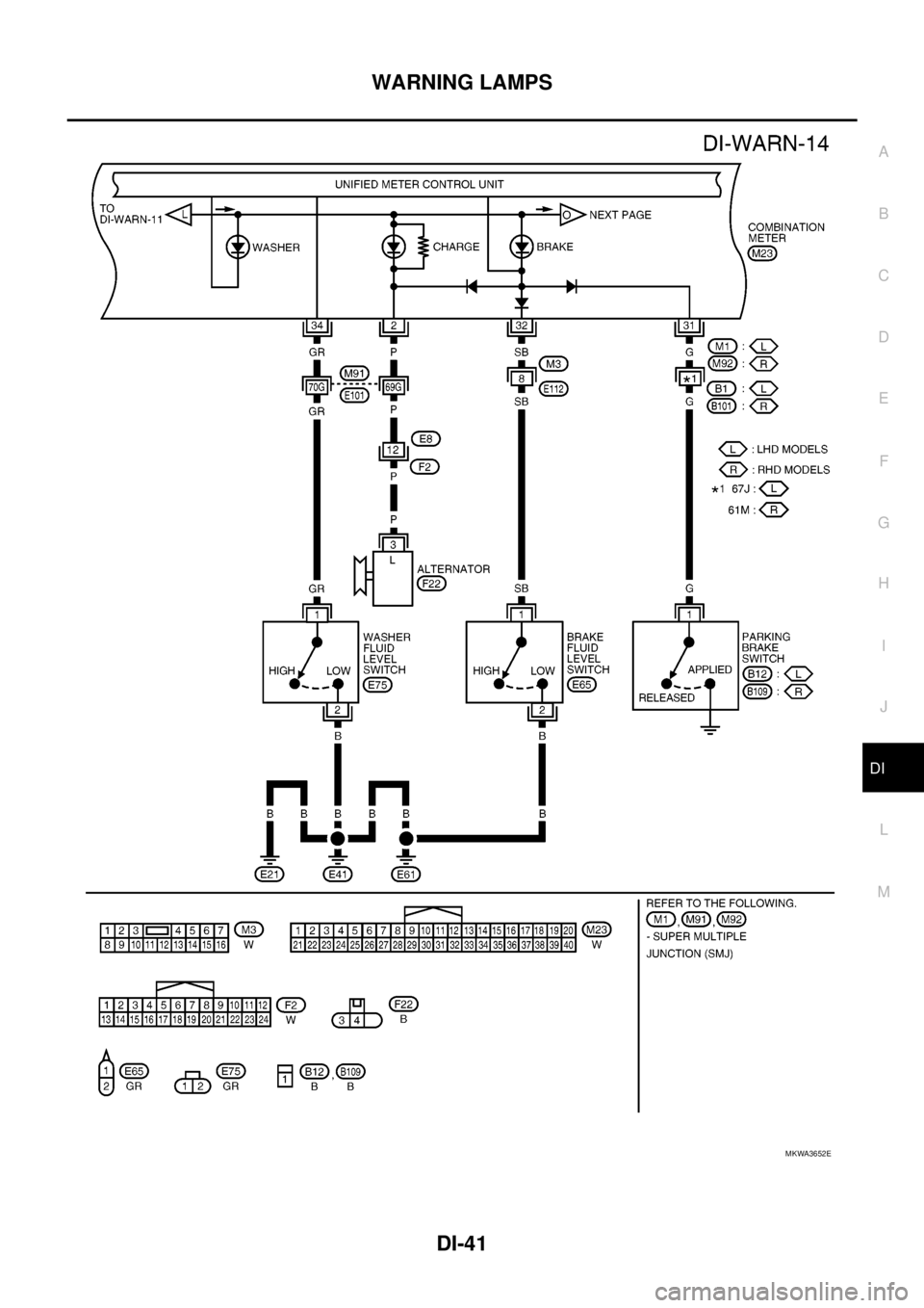
MKWA3652E
Page 952 of 3171
DI-42
WARNING LAMPS
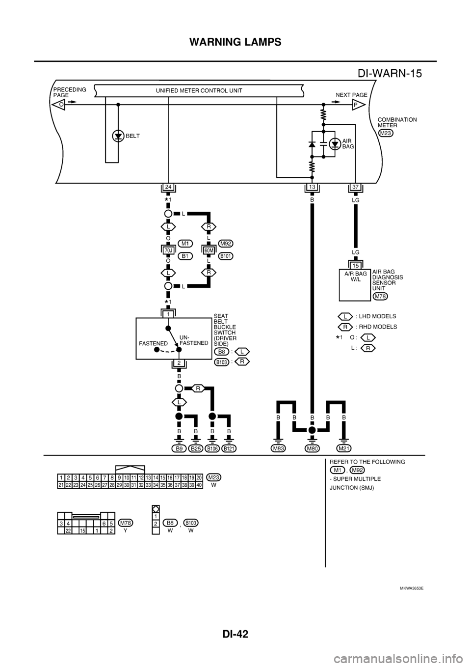
MKWA3653E
Page 953 of 3171
WARNING LAMPS
DI-43
C
D
E
F
G
H
I
J
L
MA
B
DI
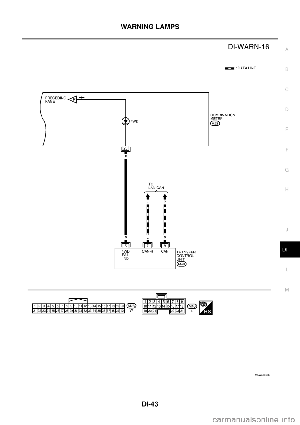
MKWA3665E
Page 954 of 3171
DI-44
WARNING LAMPS
Oil Pressure Warning Lamp Stays Off (Ignition Switch ON)
EKS00M52
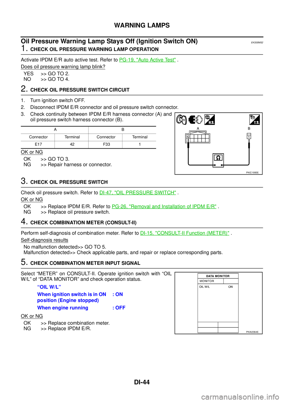
1.CHECK OIL PRESSURE WARNING LAMP OPERATION
Activate IPDM E/R auto active test. Refer toPG-19, "
Auto Active Test".
Does oil pressure warning lamp blink?
YES >> GO TO 2.
NO >> GO TO 4.
2.CHECK OIL PRESSURE SWITCH CIRCUIT
1. Turn ignition switch OFF.
2. Disconnect IPDM E/R connector and oil pressure switch connector.
3. Check continuity between IPDM E/R harness connector (A) and
oil pressure switch harness connector (B).
OK or NG
OK >> GO TO 3.
NG >> Repair harness or connector.
3.CHECK OIL PRESSURE SWITCH
Check oil pressure switch. Refer toDI-47, "
OIL PRESSURE SWITCH".
OK or NG
OK >> Replace IPDM E/R. Refer toPG-26, "Removal and Installation of IPDM E/R".
NG >> Replace oil pressure switch.
4.CHECK COMBINATION METER (CONSULT-II)
Perform self-diagnosis of combination meter. Refer toDI-15, "
CONSULT-II Function (METER)".
Self-diagnosis results
No malfunction detected>> GO TO 5.
Malfunction detected>> Check applicable parts, and repair or replace corresponding parts.
5.CHECK COMBINATION METER INPUT SIGNAL
Select “METER” on CONSULT-II. Operate ignition switch with “OIL
W/L” of “DATA MONITOR” and check operation status.
OK or NG
OK >> Replace combination meter.
NG >> Replace IPDM E/R.
AB
Connector Terminal Connector Terminal
E17 42 F33 1
PKIC1995E
“OIL W/L”
When ignition switch is in ON
position (Engine stopped):ON
When engine running : OFF
PKIA2064E
Page 955 of 3171
WARNING LAMPS
DI-45
C
D
E
F
G
H
I
J
L
MA
B
DI
Oil Pressure Warning Lamp Does Not Turn Off (Oil Pressure Is Normal)EKS00M53
NOTE:
For oil pressure inspection, refer toLU-5, "
ENGINE OIL PRESSURE CHECK".
1.CHECK OIL PRESSURE WARNING LAMP OPERATION
Activate IPDM E/R auto active test. Refer toPG-19, "
Auto Active Test".
Does oil pressure warning lamp blink?
YES >> GO TO 2.
NO >> GO TO 5.
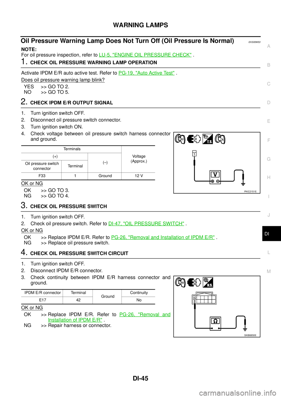
2.CHECK IPDM E/R OUTPUT SIGNAL
1. Turn ignition switch OFF.
2. Disconnect oil pressure switch connector.
3. Turn ignition switch ON.
4. Check voltage between oil pressure switch harness connector
and ground.
OK or NG
OK >> GO TO 3.
NG >> GO TO 4.
3.CHECK OIL PRESSURE SWITCH
1. Turn ignition switch OFF.
2. Check oil pressure switch. Refer toDI-47, "
OIL PRESSURE SWITCH".
OK or NG
OK >> Replace IPDM E/R. Refer toPG-26, "Removal and Installation of IPDM E/R".
NG >> Replace oil pressure switch.
4.CHECK OIL PRESSURE SWITCH CIRCUIT
1. Turn ignition switch OFF.
2. Disconnect IPDM E/R connector.
3. Check continuity between IPDM E/R harness connector and
ground.
OK or NG
OK >> Replace IPDM E/R. Refer toPG-26, "Removal and
Installation of IPDM E/R".
NG >> Repair harness or connector.
Terminals
Vo l ta g e
(Approx.) (+)
(–)
Oil pressure switch
connectorTerminal
F33 1 Ground 12 V
PKIC2151E
IPDM E/R connector Terminal
GroundContinuity
E17 42 No
SKIB6850E
Page 956 of 3171
DI-46
WARNING LAMPS
5.CHECK IPDM E/R (CONSULT-II)
Perform self-diagnosis of IPDM E/R. Refer toPG-16, "
CONSULT-II Function (IPDM E/R)".
Self-diagnosis results
No malfunction detected>>Replace combination meter.
Malfunction detected>> Check applicable parts, and repair or replace corresponding parts.
Oil Pressure Warning Lamp Keeps Blinking (Oil Level Is Normal)EKS00MM6
NOTE:
For engine oil level inspection, refer toLU-5, "
ENGINE OIL LEVEL".
If combination meter detects that oil level sensor is open or short circuit, oil level warning is displayed.
1.CHECK OIL LEVEL SENSOR
1. Turn ignition switch OFF.
2. Disconnect oil level sensor connector.
3. Check oil level sensor. Refer toDI-47, "
OIL LEVEL SENSOR".
OK or NG
OK >> GO TO 2.
NG >> Replace oil level sensor.
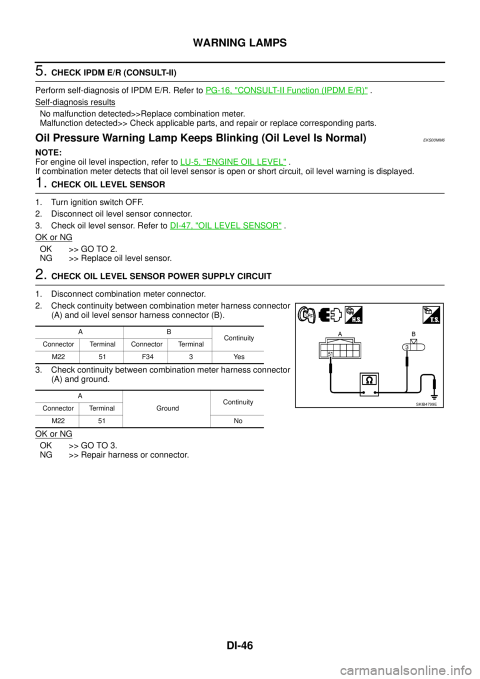
2.CHECK OIL LEVEL SENSOR POWER SUPPLY CIRCUIT
1. Disconnect combination meter connector.
2. Check continuity between combination meter harness connector
(A) and oil level sensor harness connector (B).
3. Check continuity between combination meter harness connector
(A) and ground.
OK or NG
OK >> GO TO 3.
NG >> Repair harness or connector.
AB
Continuity
Connector Terminal Connector Terminal
M22 51 F34 3 Yes
A
GroundContinuity
Connector Terminal
M22 51 No
SKIB4799E
Page 957 of 3171
WARNING LAMPS
DI-47
C
D
E
F
G
H
I
J
L
MA
B
DI
3.CHECK OIL LEVEL SENSOR GROUND CIRCUIT
1. Check continuity between combination meter harness connector
(A) and oil level sensor harness connector (B).
2. Check continuity between combination meter harness connector
(A) and ground.
OK or NG
OK >> Replace combination meter.
NG >> Repair harness or connector.
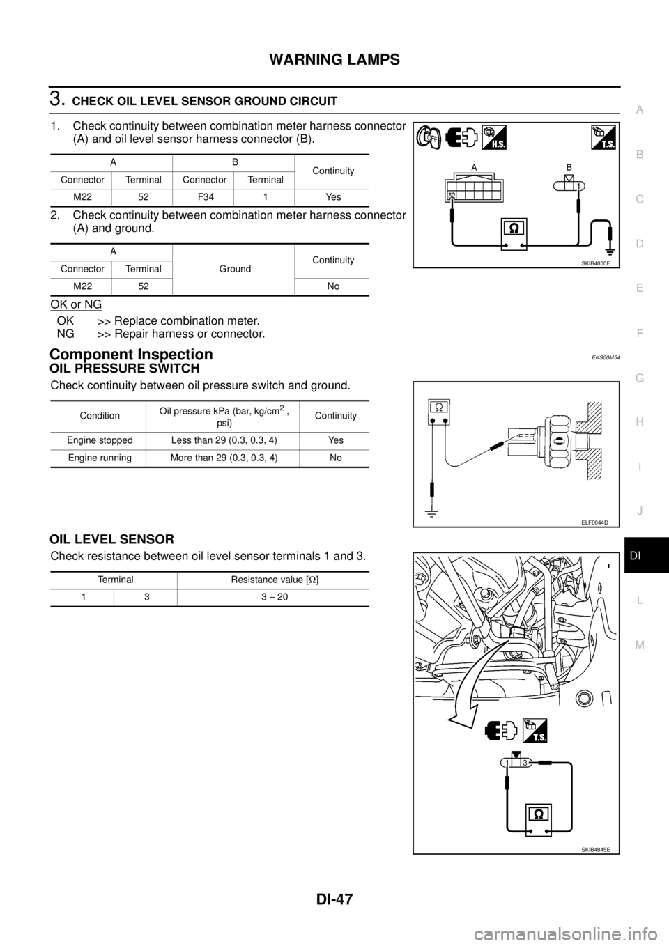
Component InspectionEKS00M54
OIL PRESSURE SWITCH
Check continuity between oil pressure switch and ground.
OIL LEVEL SENSOR
Check resistance between oil level sensor terminals 1 and 3.
AB
Continuity
Connector Terminal Connector Terminal
M22 52 F34 1 Yes
A
GroundContinuity
Connector Terminal
M22 52 No
SKIB4800E
ConditionOil pressure kPa (bar, kg/cm2,
psi)Continuity
Engine stopped Less than 29 (0.3, 0.3, 4) Yes
Engine running More than 29 (0.3, 0.3, 4) No
ELF0044D
Terminal Resistance value [W]
13 3–20
SKIB4845E
Page 958 of 3171
DI-48
A/T INDICATOR
A/T INDICATOR
PFP:24814
System DescriptionEKS00PDJ
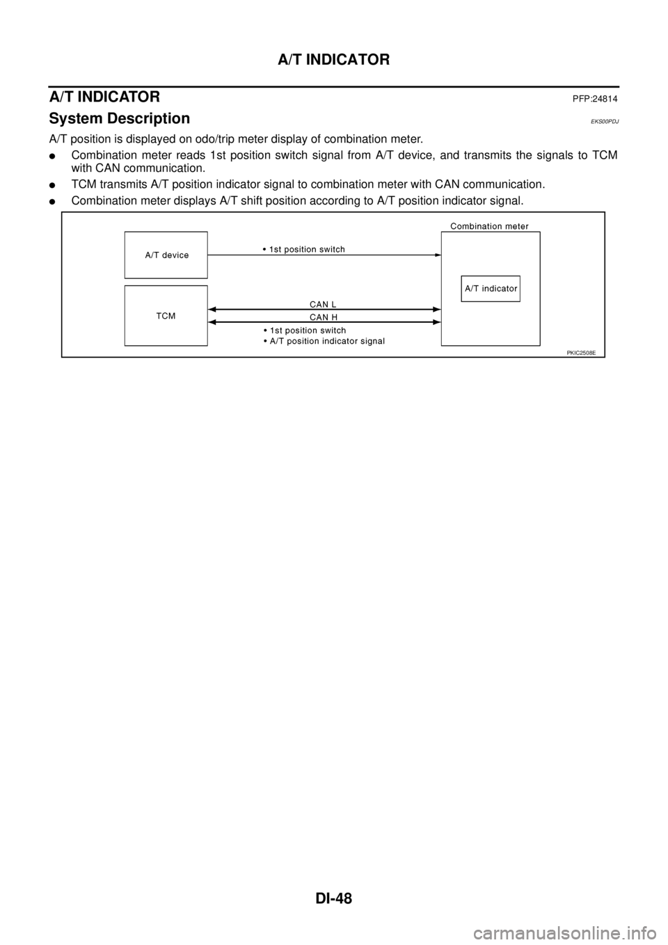
A/T position is displayed on odo/trip meter display of combination meter.
lCombination meter reads 1st position switch signal from A/T device, and transmits the signals to TCM
with CAN communication.
lTCM transmits A/T position indicator signal to combination meter with CAN communication.
lCombination meter displays A/T shift position according to A/T position indicator signal.
PKIC2508E
Page 959 of 3171
A/T INDICATOR
DI-49
C
D
E
F
G
H
I
J
L
MA
B
DI
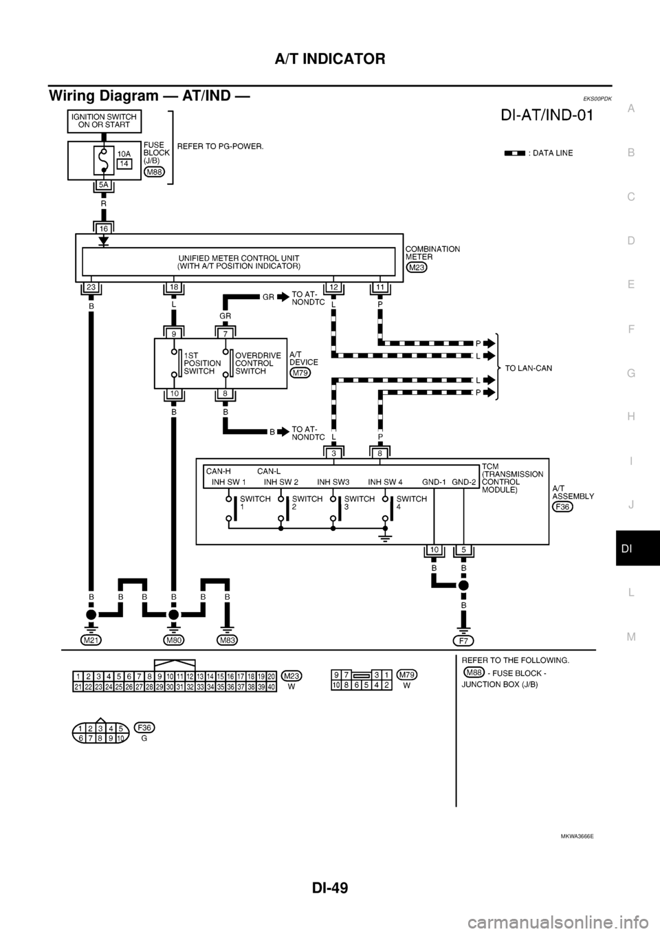
Wiring Diagram — AT/IND —EKS00PDK
MKWA3666E
Page 960 of 3171
DI-50
A/T INDICATOR
A/T Indicator Does Not Illuminate
EKS00PDL
1.CHECK SEGMENT OF A/T INDICATOR
Perform self-diagnosis mode of combination meter. Refer toDI-13, "
Self-Diagnosis Mode of Combination
Meter".
Are all segments displayed?
YES >> GO TO 2.
NO >> Replace combination meter.
2.CHECK COMBINATION METER (CONSULT-II)
Perform self-diagnosis of combination meter. Refer toDI-15, "
CONSULT-II Function (METER)".
OK or NG
OK >> GO TO 3.
NG >> Check applicable part, and repair or replace corresponding parts.
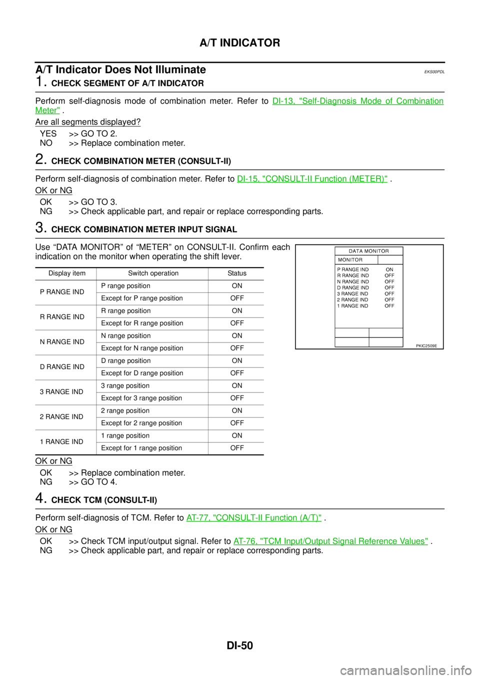
3.CHECK COMBINATION METER INPUT SIGNAL
Use “DATA MONITOR” of “METER” on CONSULT-II. Confirm each
indication on the monitor when operating the shift lever.
OK or NG
OK >> Replace combination meter.
NG >> GO TO 4.
4.CHECK TCM (CONSULT-II)
Perform self-diagnosis of TCM. Refer toAT-77, "
CONSULT-II Function (A/T)".
OK or NG
OK >> Check TCM input/output signal. Refer toAT-76, "TCM Input/Output Signal Reference Values".
NG >> Check applicable part, and repair or replace corresponding parts.
Display item Switch operation Status
P RANGE INDP range position ON
Except for P range position OFF
RRANGEINDR range position ON
Except for R range position OFF
NRANGEINDN range position ON
Except for N range position OFF
DRANGEINDD range position ON
Except for D range position OFF
3RANGEIND3 range position ON
Except for 3 range position OFF
2RANGEIND2 range position ON
Except for 2 range position OFF
1RANGEIND1 range position ON
Except for 1 range position OFF
PKIC2509E
Trending: trailer, body, service schedule, automatic transmission fluid, spare tire, power steering fluid, Timing chain
