NISSAN NAVARA 2005 Repair Workshop Manual
Manufacturer: NISSAN, Model Year: 2005, Model line: NAVARA, Model: NISSAN NAVARA 2005Pages: 3171, PDF Size: 49.59 MB
Page 931 of 3171
COMBINATION METERS
DI-21
C
D
E
F
G
H
I
J
L
MA
B
DI
Engine Speed Signal InspectionEKS00PDG
Symptom: Tachometer indication is malfunction.
1.CHECK COMBINATION METER INPUT SIGNAL
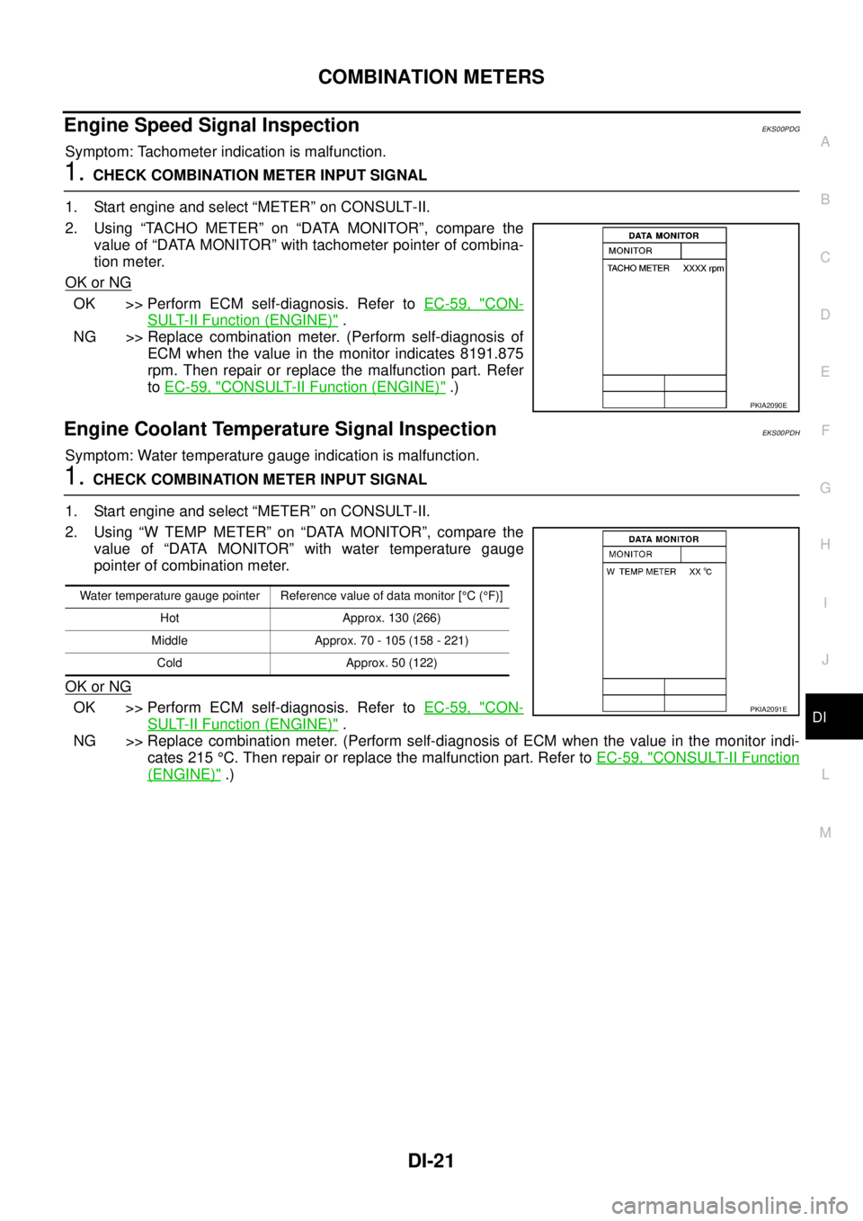
1. Start engine and select “METER” on CONSULT-II.
2. Using “TACHO METER” on “DATA MONITOR”, compare the
value of “DATA MONITOR” with tachometer pointer of combina-
tion meter.
OK or NG
OK >> Perform ECM self-diagnosis. Refer toEC-59, "CON-
SULT-II Function (ENGINE)".
NG >> Replace combination meter. (Perform self-diagnosis of
ECM when the value in the monitor indicates 8191.875
rpm. Then repair or replace the malfunction part. Refer
toEC-59, "
CONSULT-II Function (ENGINE)".)
Engine Coolant Temperature Signal InspectionEKS00PDH
Symptom: Water temperature gauge indication is malfunction.
1.CHECK COMBINATION METER INPUT SIGNAL
1. Start engine and select “METER” on CONSULT-II.
2. Using “W TEMP METER” on “DATA MONITOR”, compare the
value of “DATA MONITOR” with water temperature gauge
pointer of combination meter.
OK or NG
OK >> Perform ECM self-diagnosis. Refer toEC-59, "CON-
SULT-II Function (ENGINE)".
NG >> Replace combination meter. (Perform self-diagnosis of ECM when the value in the monitor indi-
cates 215°C. Then repair or replace the malfunction part. Refer toEC-59, "
CONSULT-II Function
(ENGINE)".)
PKIA2090E
Water temperature gauge pointer Reference value of data monitor [°C(°F)]
Hot Approx. 130 (266)
Middle Approx. 70 - 105 (158 - 221)
Cold Approx. 50 (122)
PKIA2091E
Page 932 of 3171
DI-22
COMBINATION METERS
Fuel Level Sensor Signal Inspection
EKS00L8U
Symptom:
lFuel gauge indication is malfunction.
lLow-fuel warning lamp indication is irregular.
NOTE:
The following symptoms are not malfunction.
Fuel level sensor unit
lDepending on vehicle incline or driving circumstance, the fuel level in the tank varies, and the pointer may
fluctuate.
lIf the vehicle is fueled with the ignition switch ON, the pointer moves slowly.
Low-fuel warning lamp
lDepending on vehicle incline or driving circumstance, the fuel in the tank flows and the warning lamp ON
timing may change.
1.CHECK COMBINATION METER INPUT SIGNAL
1. Select “METER” on CONSULT-II.
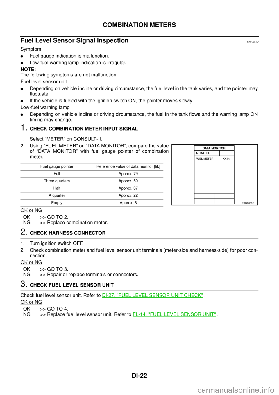
2. Using “FUEL METER” on “DATA MONITOR”, compare the value
of “DATA MONITOR” with fuel gauge pointer of combination
meter.
OK or NG
OK >> GO TO 2.
NG >> Replace combination meter.
2.CHECK HARNESS CONNECTOR
1. Turn ignition switch OFF.
2. Check combination meter and fuel level sensor unit terminals (meter-side and harness-side) for poor con-
nection.
OK or NG
OK >> GO TO 3.
NG >> Repair or replace terminals or connectors.
3.CHECK FUEL LEVEL SENSOR UNIT
Check fuel level sensor unit. Refer toDI-27, "
FUEL LEVEL SENSOR UNIT CHECK".
OK or NG
OK >> GO TO 4.
NG >> Replace fuel level sensor unit. Refer toFL-14, "
FUEL LEVEL SENSOR UNIT".
Fuel gauge pointer Reference value of data monitor [lit.]
Full Approx. 79
Three quarters Approx. 59
Half Approx. 37
A quarter Approx. 22
Empty Approx. 8
PKIA2088E
Page 933 of 3171
COMBINATION METERS
DI-23
C
D
E
F
G
H
I
J
L
MA
B
DI
4.CHECK FUEL LEVEL SENSOR UNIT CIRCUIT 1
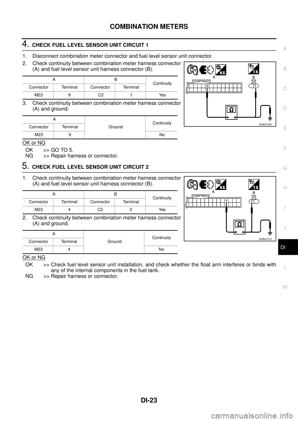
1. Disconnect combination meter connector and fuel level sensor unit connector.
2. Check continuity between combination meter harness connector
(A) and fuel level sensor unit harness connector (B).
3. Check continuity between combination meter harness connector
(A) and ground.
OK or NG
OK >> GO TO 5.
NG >> Repair harness or connector.
5.CHECK FUEL LEVEL SENSOR UNIT CIRCUIT 2
1. Check continuity between combination meter harness connector
(A) and fuel level sensor unit harness connector (B).
2. Check continuity between combination meter harness connector
(A) and ground.
OK or NG
OK >> Check fuel level sensor unit installation, and check whether the float arm interferes or binds with
any of the internal components in the fuel tank.
NG >> Repair harness or connector.
AB
Continuity
Connector Terminal Connector Terminal
M23 9 C2 1 Yes
A
GroundContinuity
Connector Terminal
M23 9 No
SKIB4720E
AB
Continuity
Connector Terminal Connector Terminal
M23 4 C2 2 Yes
A
GroundContinuity
Connector Terminal
M23 4 No
SKIB4721E
Page 934 of 3171
DI-24
COMBINATION METERS
Ambient Sensor Signal Inspection
EKS00MDQ
1.CHECK OUTPUT VOLTAGE OF COMBINATION METER
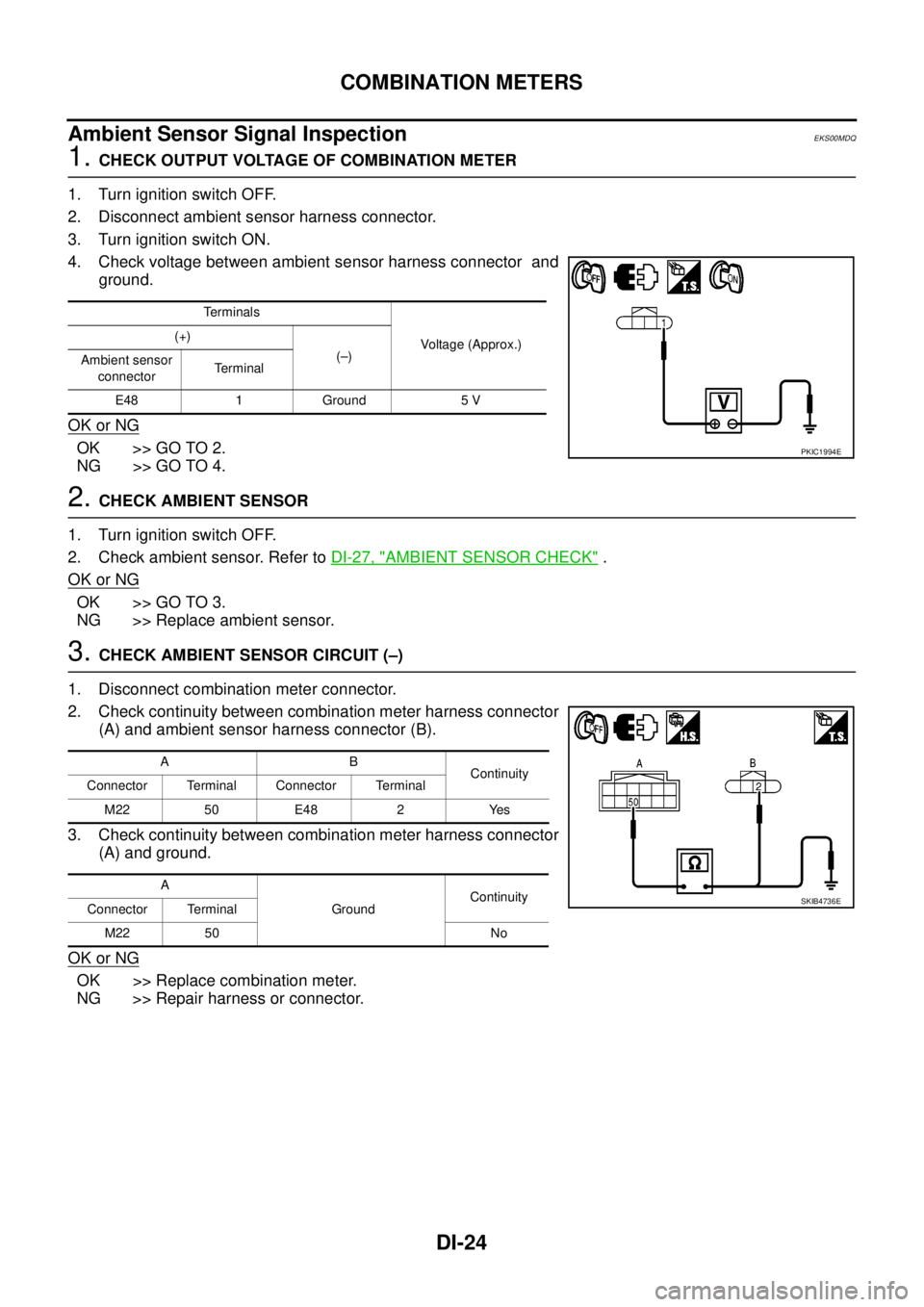
1. Turn ignition switch OFF.
2. Disconnect ambient sensor harness connector.
3. Turn ignition switch ON.
4. Check voltage between ambient sensor harness connector and
ground.
OK or NG
OK >> GO TO 2.
NG >> GO TO 4.
2.CHECK AMBIENT SENSOR
1. Turn ignition switch OFF.
2. Check ambient sensor. Refer toDI-27, "
AMBIENT SENSOR CHECK".
OK or NG
OK >> GO TO 3.
NG >> Replace ambient sensor.
3.CHECK AMBIENT SENSOR CIRCUIT (–)
1. Disconnect combination meter connector.
2. Check continuity between combination meter harness connector
(A) and ambient sensor harness connector (B).
3. Check continuity between combination meter harness connector
(A) and ground.
OK or NG
OK >> Replace combination meter.
NG >> Repair harness or connector.
Terminals
Voltage (Approx.) (+)
(–)
Ambient sensor
connectorTerminal
E48 1 Ground 5 V
PKIC1994E
AB
Continuity
Connector Terminal Connector Terminal
M22 50 E48 2 Yes
A
GroundContinuity
Connector Terminal
M22 50 No
SKIB4736E
Page 935 of 3171
COMBINATION METERS
DI-25
C
D
E
F
G
H
I
J
L
MA
B
DI
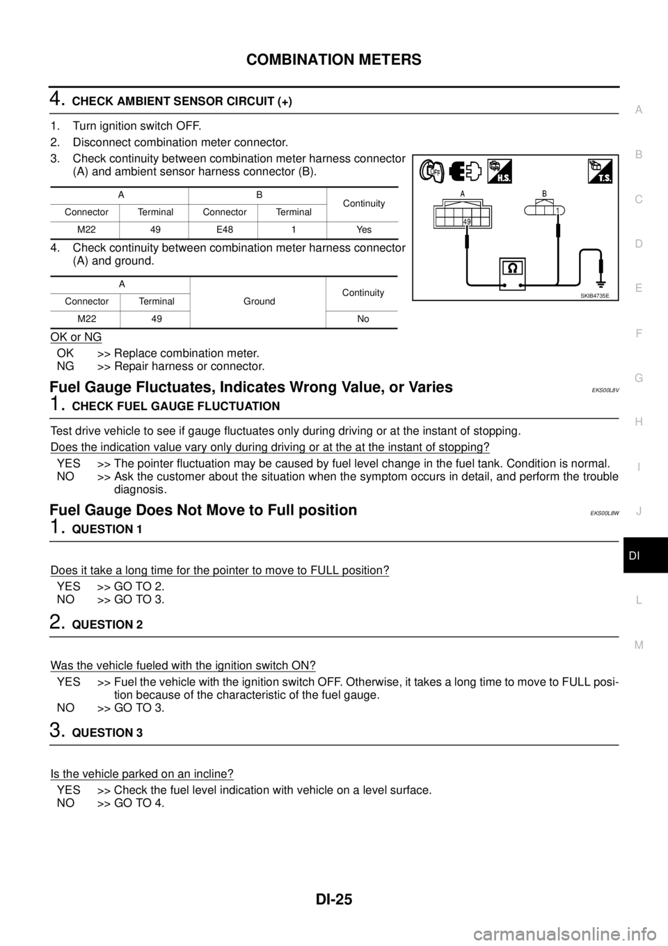
4.CHECK AMBIENT SENSOR CIRCUIT (+)
1. Turn ignition switch OFF.
2. Disconnect combination meter connector.
3. Check continuity between combination meter harness connector
(A) and ambient sensor harness connector (B).
4. Check continuity between combination meter harness connector
(A) and ground.
OK or NG
OK >> Replace combination meter.
NG >> Repair harness or connector.
Fuel Gauge Fluctuates, Indicates Wrong Value, or VariesEKS00L8V
1.CHECK FUEL GAUGE FLUCTUATION
Test drive vehicle to see if gauge fluctuates only during driving or at the instant of stopping.
Does the indication value vary only during driving or at the at the instant of stopping?
YES >> The pointer fluctuation may be caused by fuel level change in the fuel tank. Condition is normal.
NO >> Ask the customer about the situation when the symptom occurs in detail, and perform the trouble
diagnosis.
Fuel Gauge Does Not Move to Full positionEKS00L8W
1.QUESTION 1
Does it take a long time for the pointer to move to FULL position?
YES >> GO TO 2.
NO >> GO TO 3.
2.QUESTION 2
Was the vehicle fueled with the ignition switch ON?
YES >> Fuel the vehicle with the ignition switch OFF. Otherwise, it takes a long time to move to FULL posi-
tion because of the characteristic of the fuel gauge.
NO >> GO TO 3.
3.QUESTION 3
Isthevehicleparkedonanincline?
YES >> Check the fuel level indication with vehicle on a level surface.
NO >> GO TO 4.
AB
Continuity
Connector Terminal Connector Terminal
M22 49 E48 1 Yes
A
GroundContinuity
Connector Terminal
M22 49 No
SKIB4735E
Page 936 of 3171
DI-26
COMBINATION METERS
4.QUESTION 4
During driving, does the fuel gauge pointer move gradually toward EMPTY position?
YES >> Check the fuel level sensor unit. Refer toDI-27, "FUEL LEVEL SENSOR UNIT CHECK".
NO >> The float arm may interfere or bind with any of the components in the fuel tank.
DTC [U1000] CAN Communication CircuitEKS00L8X
Symptom: Displays “CAN COMM CIRC [U1000]” at the self-diagnosis result for combination meter.
1.CHECK CAN COMMUNICATION
1. Select “SELF-DIAG RESULTS” mode for “METER” with CONSULT-II.
2. Print out CONSULT-II screen.
>> Go to “LAN SYSTEM”. Refer toLAN-3, "
Precautions When Using CONSULT-II".
DTC [B2205] Vehicle Speed CircuitEKS00L8Y
Symptom: Displays “VEHICLE SPEED CIRC [B2205]” at the self-diagnosis result for combination meter.
Perform the ABS actuator and electric unit (control unit) self-diagnosis, and repair or replace malfunctioning
parts. Refer toBRC-17, "
CONSULT- II Functions".
Page 937 of 3171
COMBINATION METERS
DI-27
C
D
E
F
G
H
I
J
L
MA
B
DI
Electrical Components InspectionEKS00L8Z
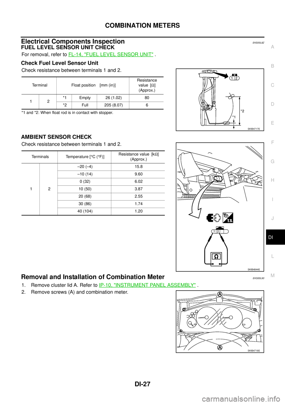
FUEL LEVEL SENSOR UNIT CHECK
For removal, refer toFL-14, "FUEL LEVEL SENSOR UNIT".
Check Fuel Level Sensor Unit
Check resistance between terminals 1 and 2.
*1 and *2: When float rod is in contact with stopper.
AMBIENT SENSOR CHECK
Check resistance between terminals 1 and 2.
Removal and Installation of Combination MeterEKS00L90
1. Remove cluster lid A. Refer toIP-10, "INSTRUMENT PANEL ASSEMBLY".
2. Remove screws (A) and combination meter.
Terminal Float position [mm (in)]Resistance
value [W]
(Approx.)
12*1 Empty 26 (1.02) 80
*2 Full 205 (8.07) 6
SKIB4717E
Terminals Temperature [°C(°F)]Resistance value [kW]
(Approx.)
12–20 (–4) 15.8
–10 (14) 9.60
0 (32) 6.02
10 (50) 3.87
20 (68) 2.55
30 (86) 1.74
40 (104) 1.20
SKIB4844E
SKIB4716E
Page 938 of 3171
DI-28
WARNING LAMPS
WARNING LAMPS
PFP:24814
System DescriptionEKS00MHA
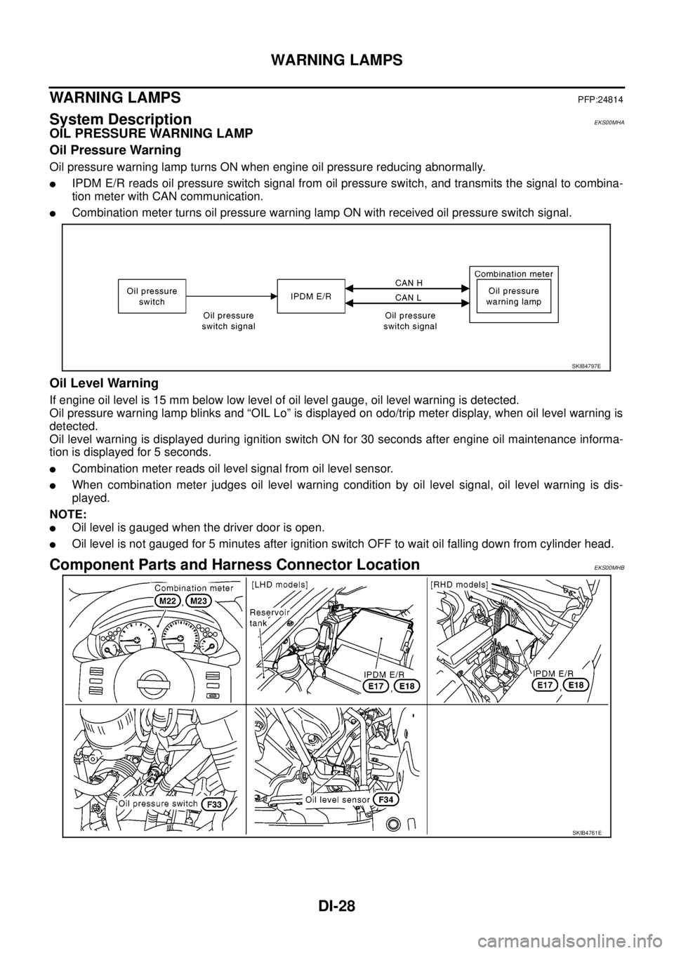
OIL PRESSURE WARNING LAMP
Oil Pressure Warning
Oil pressure warning lamp turns ON when engine oil pressure reducing abnormally.
lIPDM E/R reads oil pressure switch signal from oil pressure switch, and transmits the signal to combina-
tion meter with CAN communication.
lCombination meter turns oil pressure warning lamp ON with received oil pressure switch signal.
Oil Level Warning
If engine oil level is 15 mm below low level of oil level gauge, oil level warning is detected.
Oil pressure warning lamp blinks and “OIL Lo” is displayed on odo/trip meter display, when oil level warning is
detected.
Oil level warning is displayed during ignition switch ON for 30 seconds after engine oil maintenance informa-
tion is displayed for 5 seconds.
lCombination meter reads oil level signal from oil level sensor.
lWhen combination meter judges oil level warning condition by oil level signal, oil level warning is dis-
played.
NOTE:
lOil level is gauged when the driver door is open.
lOil level is not gauged for 5 minutes after ignition switch OFF to wait oil falling down from cylinder head.
Component Parts and Harness Connector LocationEKS00MHB
SKIB4797E
SKIB4761E
Page 939 of 3171
WARNING LAMPS
DI-29
C
D
E
F
G
H
I
J
L
MA
B
DI
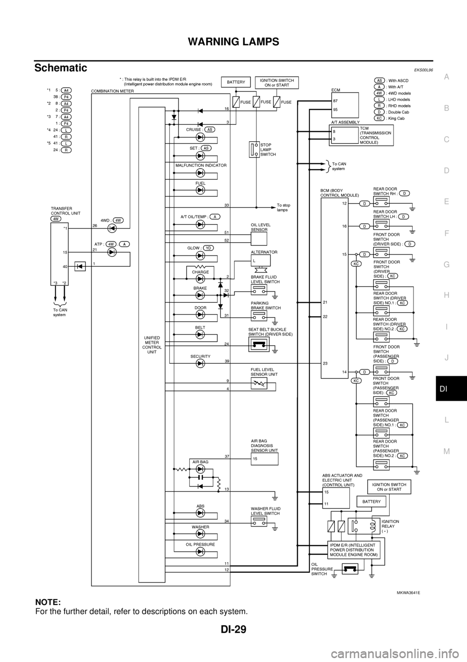
SchematicEKS00L96
NOTE:
For the further detail, refer to descriptions on each system.
MKWA3641E
Page 940 of 3171
DI-30
WARNING LAMPS
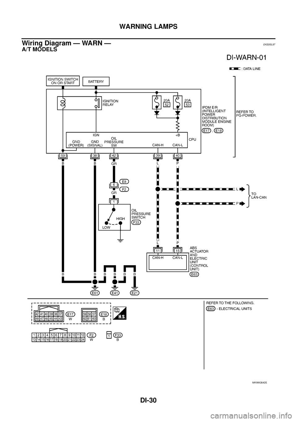
Wiring Diagram — WARN —
EKS00L97
A/T MODELS
MKWA3642E