NISSAN NOTE 2016 Service Repair Manual
Manufacturer: NISSAN, Model Year: 2016, Model line: NOTE, Model: NISSAN NOTE 2016Pages: 3641, PDF Size: 28.72 MB
Page 1731 of 3641
HEADLAMP (LO) CIRCUITEXL-79
< DTC/CIRCUIT DIAGNOSIS >
C
DE
F
G H
I
J
K
M A
B
EXL
N
O P
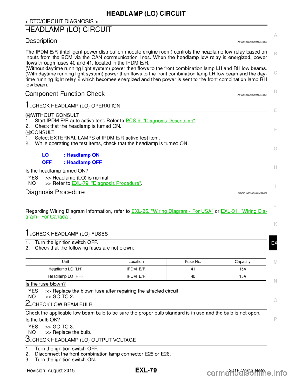
HEADLAMP (LO) CIRCUIT
DescriptionINFOID:0000000012432807
The IPDM E/R (intelligent power distribution modul e engine room) controls the headlamp low relay based on
inputs from the BCM via the CAN communication li nes. When the headlamp low relay is energized, power
flows through fuses 40 and 41, located in the IPDM E/R.
(Without daytime running light system) power then flow s to the front combination lamp LH and RH low beams.
(With daytime running light system) power then flows to the front combination lamp LH low beam and the day-
time running light relay 2 which becomes energized and t hen power is sent to the front combination lamp RH
low beam.
Component Function CheckINFOID:0000000012432808
1.CHECK HEADLAMP (LO) OPERATION
WITHOUT CONSULT
1. Start IPDM E/R auto active test. Refer to PCS-9, "
Diagnosis Description".
2. Check that the headlamp is turned ON.
CONSULT
1. Select EXTERNAL LAMPS of IP DM E/R active test item.
2. While operating the test items, check that the headlamp is turned ON.
Is the headlamp turned ON?
YES >> Headlamp (LO) is normal.
NO >> Refer to EXL-79, "
Diagnosis Procedure".
Diagnosis ProcedureINFOID:0000000012432809
Regarding Wiring Diagram information, refer to EXL-25, "Wiring Diagram - For USA" or EXL-31, "Wiring Dia-
gram - For Canada".
1.CHECK HEADLAMP (LO) FUSES
1. Turn the ignition switch OFF.
2. Check that the following fuses are not blown:
Is the fuse blown?
YES >> Replace the blown fuse after repairing the affected circuit.
NO >> GO TO 2.
2.CHECK LOW BEAM BULB
Check the applicable low beam bulb to be sure the proper bulb standard is in use and the bulb is not open.
Is the bulb OK?
YES >> GO TO 3.
NO >> Replace the bulb.
3.CHECK HEADLAMP (LO) OUTPUT VOLTAGE
1. Turn the ignition switch OFF.
2. Disconnect the front combination lamp connector E25 or E26.
3. Turn the ignition switch ON. LO : Headlamp ON
OFF : Headlamp OFF
Unit
LocationFuse No.Capacity
Headlamp LO (L H) IPDM E/R 4115A
Headlamp LO (RH) IPDM E/R4015A
Revision: August 2015 2016 Versa Note
cardiagn.com
Page 1732 of 3641

EXL-80
< DTC/CIRCUIT DIAGNOSIS >
HEADLAMP (LO) CIRCUIT
4. Turn the low beam headlamps ON.
5. With the low beam headlamps ON, check the voltage between the combination lamp connector andground.
Is the inspection result normal?
YES >> GO TO 9.
NO >> GO TO 4 (without daytime running light system). >> GO TO 5 (with daytime running light system).
4.CHECK HEADLAMP (LO) CIRCUIT FOR OPEN
1. Turn the ignition switch OFF.
2. Disconnect IPDM E/R connector E44.
3. Check continuity between the IPDM E/R harness connector E44 and the front combination lamp harness connectors E25 and E26.
Is the inspection result normal?
YES >> Replace IPDM E/R. Refer to PCS-30, "Removal and Installation".
NO >> Repair or replace the harness or connector.
5.CHECK DAYTIME RUNNING LIGHT RELAY 2 TO FR ONT COMBINATION LAMP LH CIRCUIT FOR OPEN
1. Disconnect daytime running light relay 2 connector E38.
2. Check continuity between the daytime running light relay 2 harness connector E38 and the front combina- tion lamp LH harness connector E25.
Is the inspection result normal?
YES >> GO TO 6.
NO >> Repair or replace the harness or connector.
6.CHECK DAYTIME RUNNING LIGHT RELAY 2 VOLTAGE CIRCUIT
With the low beam headlamps ON, check the voltage bet ween the daytime running light relay 2 connector E38
and ground.
Is the inspection result normal?
YES >> GO TO 7.
NO >> GO TO 8.
7.CHECK DAYTIME RUNNING LIGHT RELAY 2 GROUND CIRCUIT
Check continuity between the daytime running light relay 2 harness connector E38 and ground.
(+) (−)Voltage
Connector Terminal
LH E25 3 Ground Battery voltage
RH E26
Connector TerminalConnector Terminal Continuity
LH E44 14
E25
3Y es
RH 16E26
Connector TerminalConnector Terminal Continuity
E38 3E25 3Yes
(+)
(−)Voltage
Connector Terminal
E38 2
Ground Battery voltage
5
Revision: August 2015 2016 Versa Note
cardiagn.com
Page 1733 of 3641
HEADLAMP (LO) CIRCUITEXL-81
< DTC/CIRCUIT DIAGNOSIS >
C
DE
F
G H
I
J
K
M A
B
EXL
N
O P
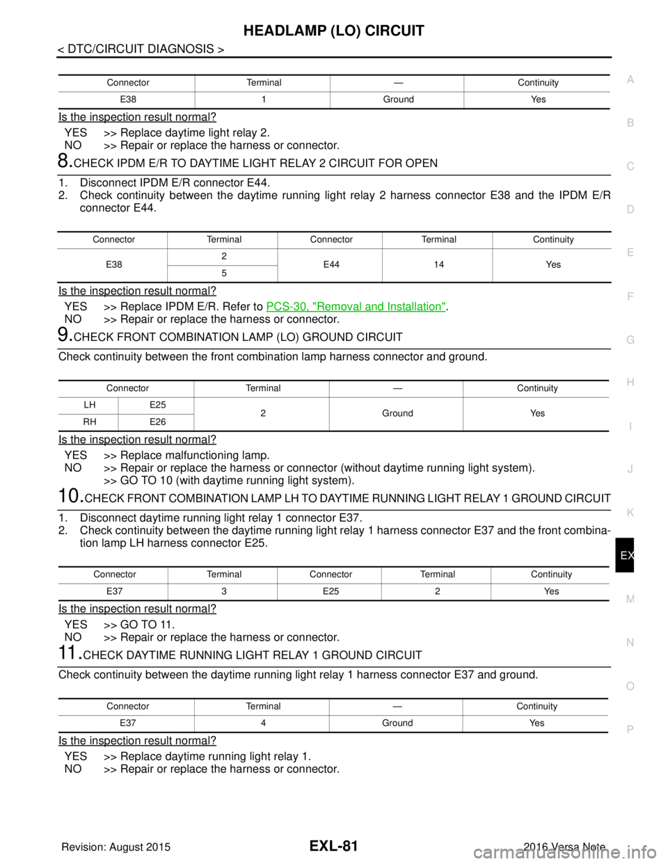
Is the inspection result normal?
YES >> Replace daytime light relay 2.
NO >> Repair or replace the harness or connector.
8.CHECK IPDM E/R TO DAYTIME LIGHT RELAY 2 CIRCUIT FOR OPEN
1. Disconnect IPDM E/R connector E44.
2. Check continuity between the daytime running li ght relay 2 harness connector E38 and the IPDM E/R
connector E44.
Is the inspection result normal?
YES >> Replace IPDM E/R. Refer to PCS-30, "Removal and Installation".
NO >> Repair or replace the harness or connector.
9.CHECK FRONT COMBINATION LAMP (LO) GROUND CIRCUIT
Check continuity between the front combination lamp harness connector and ground.
Is the inspection result normal?
YES >> Replace malfunctioning lamp.
NO >> Repair or replace the harness or connec tor (without daytime running light system).
>> GO TO 10 (with daytime running light system).
10.CHECK FRONT COMBINATION LAMP LH TO DA YTIME RUNNING LIGHT RELAY 1 GROUND CIRCUIT
1. Disconnect daytime running light relay 1 connector E37.
2. Check continuity between the daytime running light relay 1 harness connector E37 and the front combina-
tion lamp LH harness connector E25.
Is the inspection result normal?
YES >> GO TO 11.
NO >> Repair or replace the harness or connector.
11 .CHECK DAYTIME RUNNING LIGHT RELAY 1 GROUND CIRCUIT
Check continuity between the daytime running light relay 1 harness connector E37 and ground.
Is the inspection result normal?
YES >> Replace daytime running light relay 1.
NO >> Repair or replace the harness or connector.
Connector Terminal —Continuity
E38 1Ground Yes
ConnectorTerminalConnector Terminal Continuity
E38 2
E44 14 Yes
5
Connector Terminal —Continuity
LH E25
2 Ground Yes
RH E26
Connector TerminalConnector Terminal Continuity
E37 3E25 2Yes
Connector Terminal —Continuity
E37 4Ground Yes
Revision: August 2015 2016 Versa Note
cardiagn.com
Page 1734 of 3641
EXL-82
< DTC/CIRCUIT DIAGNOSIS >
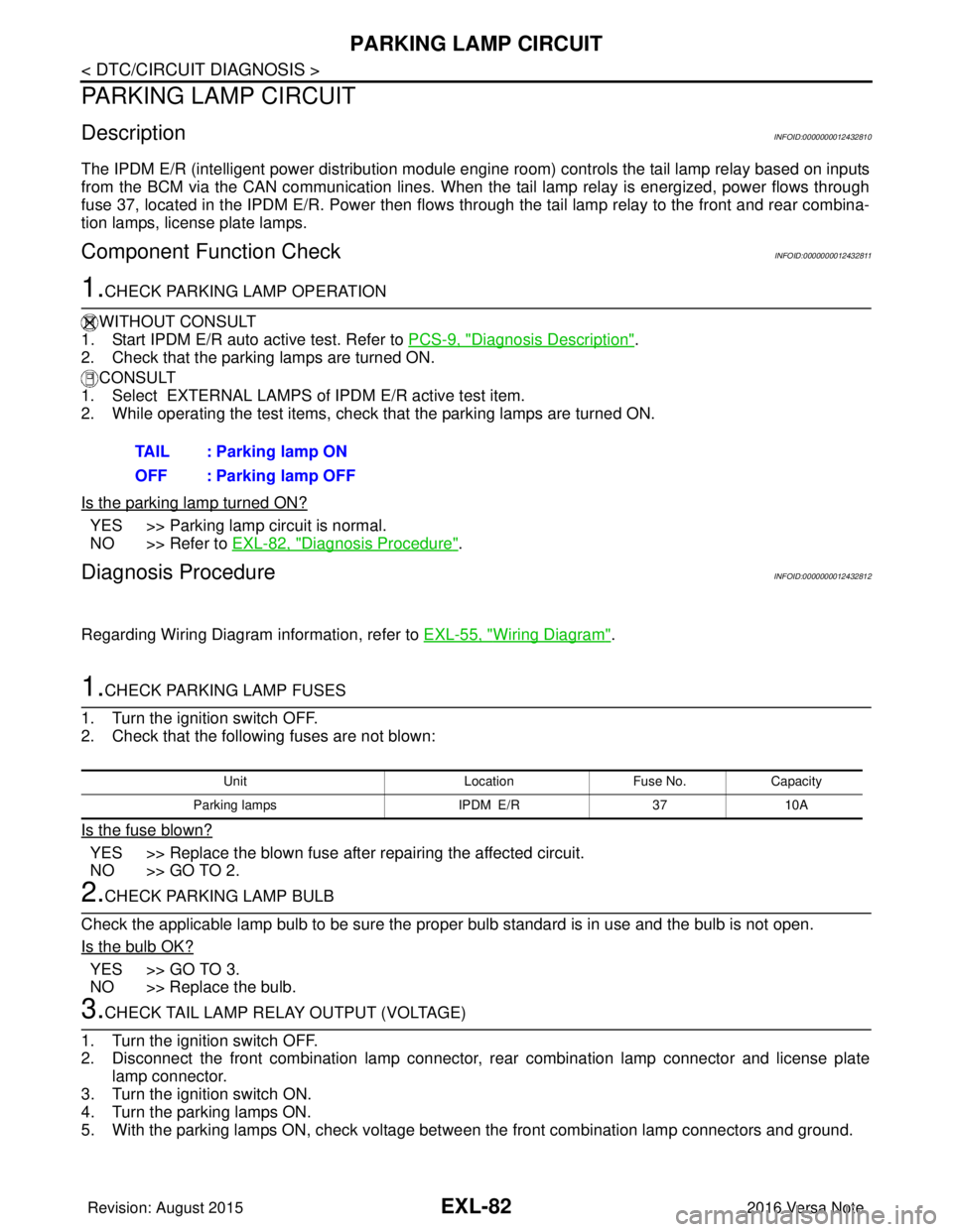
PARKING LAMP CIRCUIT
PARKING LAMP CIRCUIT
DescriptionINFOID:0000000012432810
The IPDM E/R (intelligent power distribution module engine room) controls the tail lamp relay based on inputs
from the BCM via the CAN communication lines. When the tail lamp relay is energized, power flows through
fuse 37, located in the IPDM E/R. Power then flows through the tail lamp relay to the front and rear combina-
tion lamps, license plate lamps.
Component Function CheckINFOID:0000000012432811
1.CHECK PARKING LAMP OPERATION
WITHOUT CONSULT
1. Start IPDM E/R auto active test. Refer to PCS-9, "
Diagnosis Description".
2. Check that the parking lamps are turned ON.
CONSULT
1. Select EXTERNAL LAMPS of IPDM E/R active test item.
2. While operating the test items, check that the parking lamps are turned ON.
Is the parking lamp turned ON?
YES >> Parking lamp circuit is normal.
NO >> Refer to EXL-82, "
Diagnosis Procedure".
Diagnosis ProcedureINFOID:0000000012432812
Regarding Wiring Diagram information, refer to EXL-55, "Wiring Diagram".
1.CHECK PARKING LAMP FUSES
1. Turn the ignition switch OFF.
2. Check that the following fuses are not blown:
Is the fuse blown?
YES >> Replace the blown fuse after repairing the affected circuit.
NO >> GO TO 2.
2.CHECK PARKING LAMP BULB
Check the applicable lamp bulb to be sure the proper bulb standard is in use and the bulb is not open.
Is the bulb OK?
YES >> GO TO 3.
NO >> Replace the bulb.
3.CHECK TAIL LAMP RELAY OUTPUT (VOLTAGE)
1. Turn the ignition switch OFF.
2. Disconnect the front combination lamp connector, rear combination lamp connector and license plate
lamp connector.
3. Turn the ignition switch ON.
4. Turn the parking lamps ON.
5. With the parking lamps ON, check voltage between the front combination lamp connectors and ground. TAIL : Parking lamp ON
OFF : Parking lamp OFF
Unit
LocationFuse No.Capacity
Parking lamps IPDM E/R3710A
Revision: August 2015 2016 Versa Note
cardiagn.com
Page 1735 of 3641

PARKING LAMP CIRCUITEXL-83
< DTC/CIRCUIT DIAGNOSIS >
C
DE
F
G H
I
J
K
M A
B
EXL
N
O P
6. With the parking lamps ON, check voltage betw een the rear combination lamp connectors and ground.
7. With the parking lamps ON, check voltage bet ween the license plate lamp connector and ground.
Are the inspection results normal?
YES >> GO TO 5.
NO >> GO TO 4.
4.CHECK PARKING, LICENSE PLATE AND TAIL LAMP CIRCUIT (OPEN)
1. Turn the ignition switch OFF.
2. Disconnect IPDM E/R connector.
3. Check continuity between the IPDM E/R harness connector and the front combination lamp harness con- nector.
4. Check continuity between the IPDM E/R harness connector and the rear combination lamp harness con- nector.
5. Check continuity between the IPDM E/R harness connector and license plate lamp connector.
(+) (−)V olt a g e
Connector Terminal
LH E27
7
Ground Battery voltage
E29
5
RH E28
7
E30 5
(+)
(−)V olt a g e
Connector Terminal
LH B25 1Ground Battery voltage
RH B27
(+) (−)V olt a ge
Connector Terminal
LH D507 1Ground Battery voltage
RH D508
Connector TerminalConnector Terminal Continuity
LH E45 23 E27
7
Ye s
E29
5
RH E28
7
E30 5
ConnectorTerminalConnector TerminalContinuity
LH E45 23 B25
1Y es
RH B27
ConnectorTerminalConnector TerminalContinuity
E45 23D507
1Yes
D508
Revision: August 2015 2016 Versa Note
cardiagn.com
Page 1736 of 3641

EXL-84
< DTC/CIRCUIT DIAGNOSIS >
PARKING LAMP CIRCUIT
Are the inspection results normal?
YES >> Replace IPDM E/R. Refer to PCS-30, "Removal and Installation".
NO >> Repair or replace the harness or connector.
5.CHECK PARKING, LICENSE A ND TAIL LAMP GROUND CIRCUITS
1. Check continuity between the front co mbination lamp harness connectors and ground.
2. Check continuity between the rear co mbination lamp harness connectors and ground.
3. Check continuity between the license plate lamp harness connectors and ground.
Are the inspection results normal?
YES >> Replace the malfunctioning lamp.
NO >> Repair or replace the harness or connector.
Connector Terminal —Continuity
LH E27
8
Ground Yes
E29
6
RH E28
8
E30 6
Connector Terminal —Continuity
LH B25
6 Ground Yes
RH B27
Connector Terminal —Continuity
B507 2Ground Yes
B508
Revision: August 2015 2016 Versa Note
cardiagn.com
Page 1737 of 3641
TURN SIGNAL LAMP CIRCUITEXL-85
< DTC/CIRCUIT DIAGNOSIS >
C
DE
F
G H
I
J
K
M A
B
EXL
N
O P
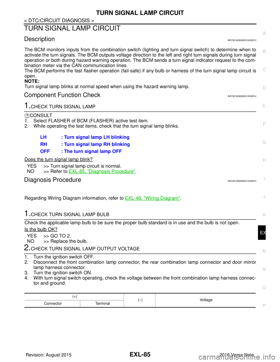
TURN SIGNAL LAMP CIRCUIT
DescriptionINFOID:0000000012432813
The BCM monitors inputs from the combination switch (lighting and turn signal switch) to determine when to
activate the turn signals. The BCM outputs voltage direction to the left and right turn signals during turn signal
operation or both during hazard warning operation. The BCM sends a turn signal indicator request to the com-
bination meter via the CAN communication lines.
The BCM performs the fast flasher operation (fail-safe) if any bulb or harness of the turn signal lamp circuit is
open.
NOTE:
Turn signal lamp blinks at normal speed when using the hazard warning lamp.
Component Function CheckINFOID:0000000012432814
1.CHECK TURN SIGNAL LAMP
CONSULT
1. Select FLASHER of BCM (FLASHER) active test item.
2. While operating the test items, check that the turn signal lamp blinks.
Does the turn signal lamp blink?
YES >> Turn signal lamp circuit is normal.
NO >> Refer to EXL-85, "
Diagnosis Procedure".
Diagnosis ProcedureINFOID:0000000012432815
Regarding Wiring Diagram information, refer to EXL-48, "Wiring Diagram".
1.CHECK TURN SIGNAL LAMP BULB
Check the applicable lamp bulb to be sure the proper bulb standard is in use and the bulb is not open.
Is the bulb OK?
YES >> GO TO 2.
NO >> Replace the bulb.
2.CHECK TURN SIGNAL LA MP OUTPUT VOLTAGE
1. Turn the ignition switch OFF.
2. Disconnect the front combination lamp connector, the rear combination lamp connector and door mirror
lamp harness connector.
3. Turn the ignition switch ON.
4. With turn signal switch operating, check the vo ltage between the front combination lamp harness connec-
tor and ground. LH : Turn signal lamp LH blinking
RH : Turn signal lamp RH blinking
OFF : The turn signal lamp OFF
(+)
(−) Voltage
Connector Terminal
Revision: August 2015 2016 Versa Note
cardiagn.com
Page 1738 of 3641
EXL-86
< DTC/CIRCUIT DIAGNOSIS >
TURN SIGNAL LAMP CIRCUIT
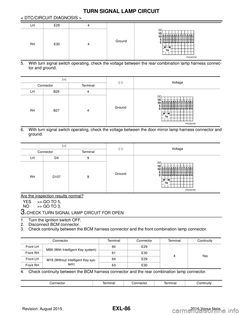
5. With turn signal switch operating, check the voltage between the rear combination lamp harness connec-tor and ground.
6. With turn signal switch operating, check the vo ltage between the door mirror lamp harness connector and
ground.
Are the inspection results normal?
YES >> GO TO 5.
NO >> GO TO 3.
3.CHECK TURN SIGNAL LAMP CIRCUIT FOR OPEN
1. Turn the ignition switch OFF.
2. Disconnect BCM connector.
3. Check continuity between the BCM harness connector and the front combination lamp connector.
4. Check continuity between the BCM harness connector and the rear combination lamp connector.
LH E29 4
Ground
RH E30 4
(+) (−) Voltage
Connector Terminal
LH B25 4
Ground
RH B27 4
(+) (−) Voltage
Connector Terminal
LH D4 9
Ground
RH D107 9
PKIC6370E
PKIC6370E
PKIC6370E
Connector Terminal Connector Terminal Continuity
Front LH M99 (With Intelligent Key system) 60
E29
4Yes
Front RH
61E30
Front LH M19 (Without Intelligent Key sys-
tem) 64
E29
Front RH 63E30
Connector Terminal Connector Terminal Continuity
Revision: August 2015 2016 Versa Note
cardiagn.com
Page 1739 of 3641
TURN SIGNAL LAMP CIRCUITEXL-87
< DTC/CIRCUIT DIAGNOSIS >
C
DE
F
G H
I
J
K
M A
B
EXL
N
O P
5. Check continuity between the BCM harness connector and the door mirror lamp connector.
Are the inspection results normal?
YES >> GO TO 4.
NO >> Repair or replace the harness or connector.
4.CHECK TURN SIGNAL LAMP SHORT CIRCUIT
Check continuity between the BCM harness connector and ground.
Is the inspection results normal?
YES >> Repair or replace the harness or connector.
NO >> Replace BCM. Refer to BCS-74, "
Removal and Installation" (with Intelligent Key system) or BCS-
137, "Removal and Installation" (without Intelligent Key system).
5.CHECK TURN SIGNAL LAMP GROUND CIRCUIT
1. Check continuity between the front combination lamp harness connector and ground.
2. Check continuity between the rear combination lamp harness connector and ground.
3. Check continuity between the door mirror lamp harness connector and ground.
Are the inspection results normal?
YES >> Replace the malfunctioning lamp.
NO >> Repair or replace the harness or connector.
Rear LH M99 (With Intelligent Key sys-
tem) 60
B25
4Y es
Rear RH
61B27
Rear LH M19 (Without Intelligent Key
system) 64
B25
Rear RH 63B27
Connector Terminal Connector Terminal Continuity
LH M99 (With Intelligent Key sys-
tem) 60
D4
9Y es
RH
61D107
LH M19 (Without Intelligent Key
system) 64
D4
RH 63D107
Connector Terminal—Continuity
LH M99 (With Intelligent Key system) 60
Ground No
RH
61
LH M19 (Without Intelligent Key system) 64
RH 63
ConnectorTerminal —Continuity
Front LH E29
6 Ground Yes
Front RH E30
Connector Terminal —Continuity
Rear LH B25
6 Ground Yes
Rear RH B27
Connector Terminal —Continuity
LH D4
10 Ground Yes
RH D107
Revision: August 2015 2016 Versa Note
cardiagn.com
Page 1740 of 3641

EXL-88
< DTC/CIRCUIT DIAGNOSIS >
FRONT FOG LAMP CIRCUIT
FRONT FOG LAMP CIRCUIT
Component Function CheckINFOID:0000000012432816
1.CHECK FRONT FOG LAMP OPERATION
WITHOUT CONSULT
1. Start IPDM E/R auto active test. Refer to PCS-9, "
Diagnosis Description".
2. Check that the front fog lamp is turned ON.
CONSULT
1. Select EXTERNAL LAMPS of IPDM E/R active test item.
2. While operating the test items, check that the front fog lamp is turned ON.
Is the front fog lamp turned ON?
YES >> Front fog lamp circuit is normal.
NO >> Refer to EXL-88, "
Diagnosis Procedure".
Diagnosis ProcedureINFOID:0000000012432817
Regarding Wiring Diagram information, refer to EXL-43, "Wiring Diagram".
1.CHECK FRONT FOG LAMP FUSE
1. Turn ignition switch OFF.
2. Check that the following fuse is not blown:
Is the fuse blown?
YES >> GO TO 2.
NO >> Replace the blown fuse after repairing the affected circuit.
2.CHECK FOG LAMP BULB
Check the applicable fog lamp bulb to be sure the proper bulb standard is in use and the bulb is not open.
Is the bulb OK?
YES >> GO TO 3.
NO >> Replace the bulb.
3.CHECK FRONT FOG LAMP OUTPUT VOLTAGE
CONSULT ACTIVE TEST
1. Turn ignition switch OFF.
2. Disconnect front fog lamp connector.
3. Turn ignition switch ON.
4. Select EXTERNAL LAMPS of IPDM E/R active test item.
5. While operating the fog lamps, check voltage between front fog lamp harness connector and ground.
FOG : Front fog lamp ON
OFF : Front fog lamp OFF
Unit
Fuse No.Capacity
Front fog lamp 3115 A
(+)
(−) Test item Vo l ta g e
(Approx.)
Front fog lamp
Connector Terminal
Revision: August 2015 2016 Versa Note
cardiagn.com