NISSAN NOTE 2016 Service Repair Manual
Manufacturer: NISSAN, Model Year: 2016, Model line: NOTE, Model: NISSAN NOTE 2016Pages: 3641, PDF Size: 28.72 MB
Page 1721 of 3641
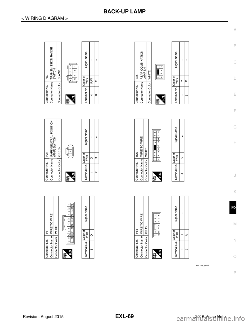
BACK-UP LAMPEXL-69
< WIRING DIAGRAM >
C
DE
F
G H
I
J
K
M A
B
EXL
N
O P
ABLIA8088GB
Revision: August 2015 2016 Versa Note
cardiagn.com
Page 1722 of 3641
EXL-70
< WIRING DIAGRAM >
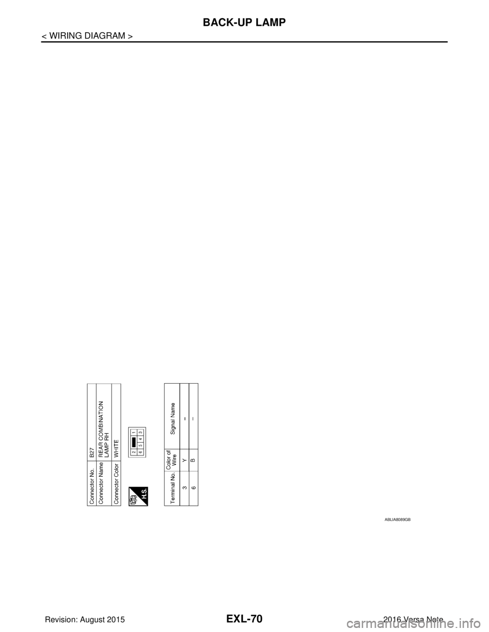
BACK-UP LAMP
ABLIA8089GB
Revision: August 20152016 Versa Note
cardiagn.com
Page 1723 of 3641
DIAGNOSIS AND REPAIR WORKFLOWEXL-71
< BASIC INSPECTION >
C
DE
F
G H
I
J
K
M A
B
EXL
N
O P
BASIC INSPECTION
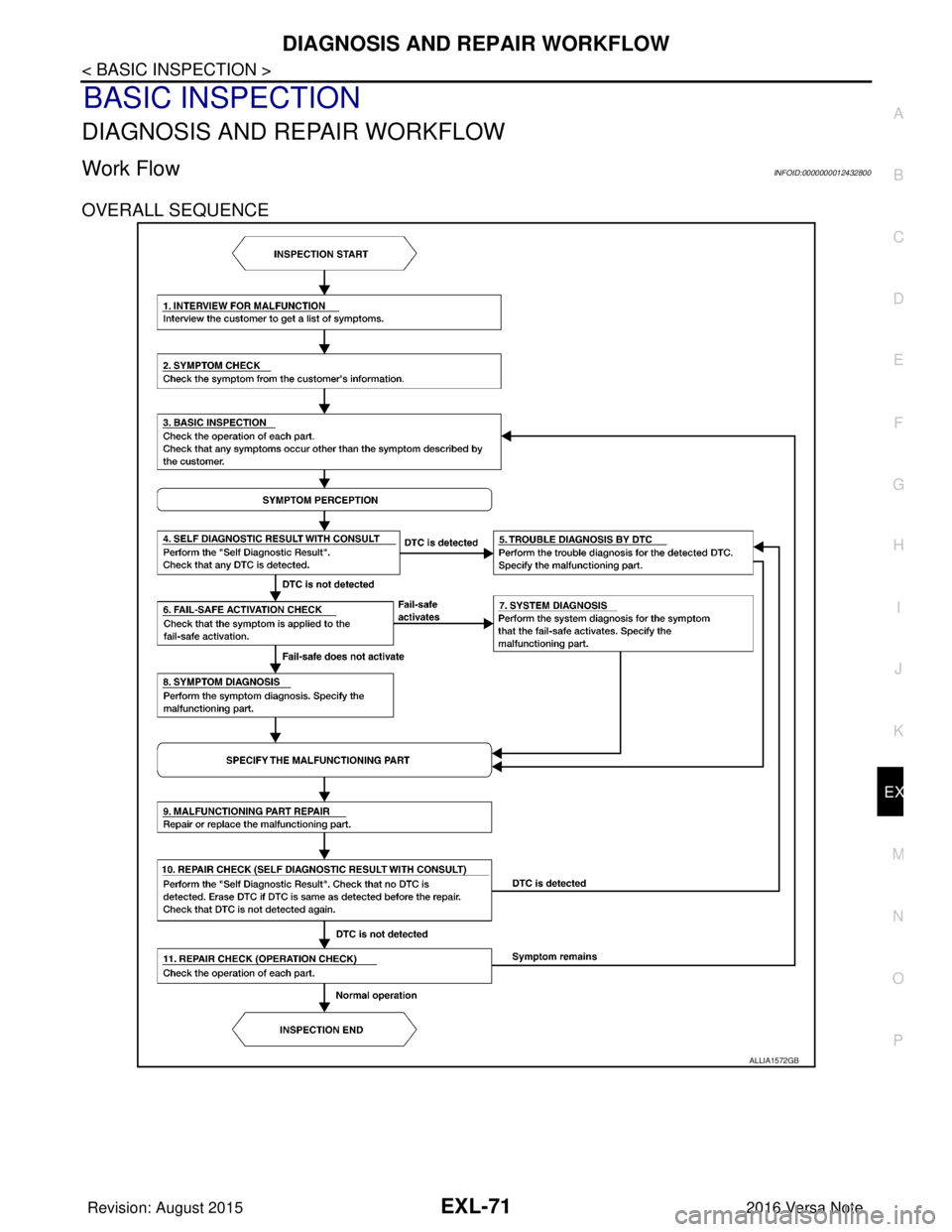
DIAGNOSIS AND REPAIR WORKFLOW
Work FlowINFOID:0000000012432800
OVERALL SEQUENCE
ALLIA1572GB
Revision: August 2015 2016 Versa Note
cardiagn.com
Page 1724 of 3641
EXL-72
< BASIC INSPECTION >
DIAGNOSIS AND REPAIR WORKFLOW
DETAILED FLOW
1.INTERVIEW FOR MALFUNCTION
Find out what the customer's concerns are.
>> GO TO 2.
2.SYMPTOM CHECK
Verify the symptom from the customer's information.
>> GO TO 3.
3.BASIC INSPECTION
Check the operation of each part. Check that any conc erns occur other than those mentioned in the customer
interview.
>> GO TO 4.
4.SELF DIAGNOSTIC RE SULT WITH CONSULT
Perform the “Self Diagnostic Result”. Check that any DTC is detected.
Is any DTC detected?
YES >> GO TO 5.
NO >> GO TO 6.
5.TROUBLE DIAGNOSIS BY DTC
Perform the trouble diagnosis for the detect ed DTC. Specify the malfunctioning part.
>> GO TO 9.
6.FAIL-SAFE ACTIVATION CHECK
Determine if the customer's concern is related to fail-safe activation.
Does the fail-safe activate?
YES >> GO TO 7.
NO >> GO TO 8.
7.SYSTEM DIAGNOSIS
Perform the system diagnosis for the system in which the fail-safe activates. Specify the malfunctioning part.
>> GO TO 9.
8.SYMPTOM DIAGNOSIS
Perform the symptom diagnosis, refer to EXL-91, "
Symptom Table". Specify the malfunctioning part.
>> GO TO 9.
9.MALFUNCTION PART REPAIR
Repair or replace the malfunctioning part.
>> GO TO 10.
10.REPAIR CHECK (SELF-DIAGNOSTIC RESULT WITH CONSULT)
Perform the “Self Diagnostic Result”. Verify that no DTCs are detected. Erase all DTCs detected prior to the
repair. Verify that DTC is not detected again.
Is any DTC detected?
Revision: August 2015 2016 Versa Note
cardiagn.com
Page 1725 of 3641

DIAGNOSIS AND REPAIR WORKFLOWEXL-73
< BASIC INSPECTION >
C
DE
F
G H
I
J
K
M A
B
EXL
N
O P
YES >> GO TO 5.
NO >> GO TO 11.
11 .REPAIR CHECK (OPERATION CHECK)
Check the operation of each part.
Does it operate normally?
YES >> Inspection End.
NO >> GO TO 3.
Revision: August 2015 2016 Versa Note
cardiagn.com
Page 1726 of 3641
EXL-74
< DTC/CIRCUIT DIAGNOSIS >
POWER SUPPLY AND GROUND CIRCUIT
DTC/CIRCUIT DIAGNOSIS
POWER SUPPLY AND GROUND CIRCUIT
BCM (BODY CONTROL SYSTEM) (WITH INTELLIGENT KEY SYSTEM)
BCM (BODY CONTROL SYSTEM) (WITH INTELLIGENT KEY SYSTEM) : Diagnosis
Procedure
INFOID:0000000012542318
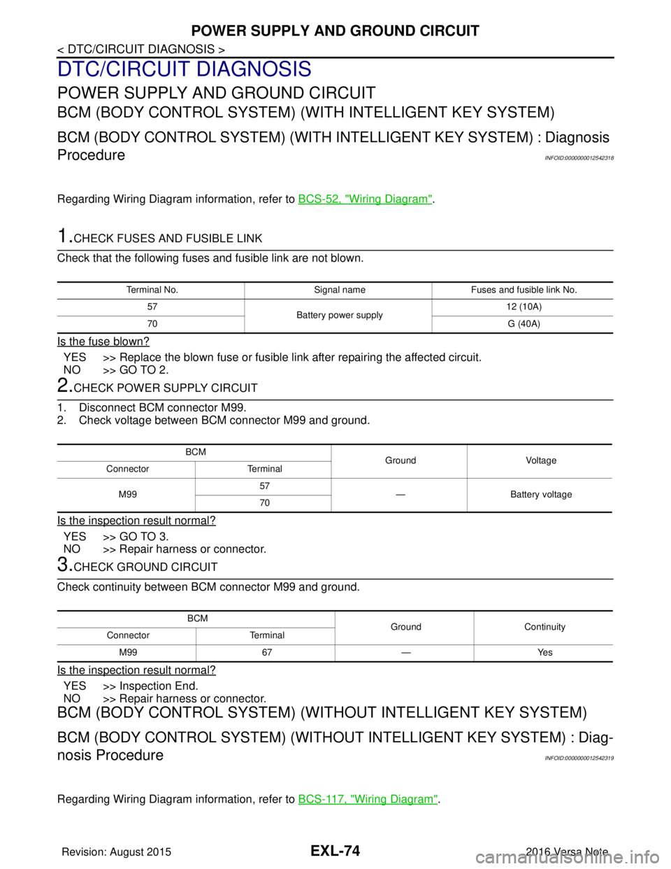
Regarding Wiring Diagram information, refer to BCS-52, "Wiring Diagram".
1.CHECK FUSES AND FUSIBLE LINK
Check that the following fuses and fusible link are not blown.
Is the fuse blown?
YES >> Replace the blown fuse or fusible link after repairing the affected circuit.
NO >> GO TO 2.
2.CHECK POWER SUPPLY CIRCUIT
1. Disconnect BCM connector M99.
2. Check voltage between BCM connector M99 and ground.
Is the inspection result normal?
YES >> GO TO 3.
NO >> Repair harness or connector.
3.CHECK GROUND CIRCUIT
Check continuity between BCM connector M99 and ground.
Is the inspection result normal?
YES >> Inspection End.
NO >> Repair harness or connector.
BCM (BODY CONTROL SYSTEM) (WIT HOUT INTELLIGENT KEY SYSTEM)
BCM (BODY CONTROL SYSTEM) (WITHOUT INTELLIGENT KEY SYSTEM) : Diag-
nosis Procedure
INFOID:0000000012542319
Regarding Wiring Diagram information, refer to BCS-117, "Wiring Diagram".
Terminal No.Signal nameFuses and fusible link No.
57 Battery power supply 12 (10A)
70 G (40A)
BCM
Ground Voltage
Connector Terminal
M99 57
— Battery voltage
70
BCM GroundContinuity
Connector Terminal
M99 67—Yes
Revision: August 2015 2016 Versa Note
cardiagn.com
Page 1727 of 3641
POWER SUPPLY AND GROUND CIRCUITEXL-75
< DTC/CIRCUIT DIAGNOSIS >
C
DE
F
G H
I
J
K
M A
B
EXL
N
O P
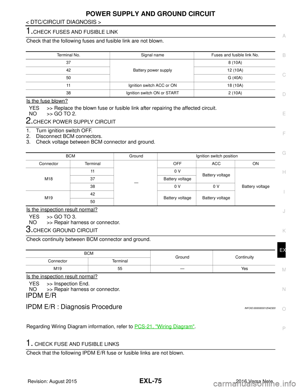
1.CHECK FUSES AND FUSIBLE LINK
Check that the following fuses and fusible link are not blown.
Is the fuse blown?
YES >> Replace the blown fuse or fusible link after repairing the affected circuit.
NO >> GO TO 2.
2.CHECK POWER SUPPLY CIRCUIT
1. Turn ignition switch OFF.
2. Disconnect BCM connectors.
3. Check voltage between BCM connector and ground.
Is the inspection result normal?
YES >> GO TO 3.
NO >> Repair harness or connector.
3.CHECK GROUND CIRCUIT
Check continuity between BCM connector and ground.
Is the inspection result normal?
YES >> Inspection End.
NO >> Repair harness or connector.
IPDM E/R
IPDM E/R : Diagnosis ProcedureINFOID:0000000012542320
Regarding Wiring Diagram information, refer to PCS-21, "Wiring Diagram".
1. CHECK FUSE AND FUSIBLE LINKS
Check that the following IPDM E/R fuse or fusible links are not blown.
Terminal No. Signal nameFuses and fusible link No.
37 Battery power supply 8 (10A)
42 12 (10A)
50 G (40A)
11 Ignition switch ACC or ON 18 (10A)
38 Ignition switch ON or START 2 (10A)
BCMGround Ignition switch position
Connector Terminal
—OFF
ACC ON
M18 11
0 V
Battery voltage
Battery voltage
37
Battery voltage
38 0 V0 V
M19 42
Battery voltage Battery voltage
50
BCM GroundContinuity
Connector Terminal
M19 55—Yes
Revision: August 2015 2016 Versa Note
cardiagn.com
Page 1728 of 3641

EXL-76
< DTC/CIRCUIT DIAGNOSIS >
POWER SUPPLY AND GROUND CIRCUIT
Is the fuse blown?
YES >> Replace the blown fuse or fusible link after repairing the affected circuit.
NO >> GO TO 2.
2. CHECK BATTERY POWER SUPPLY CIRCUIT
1. Disconnect IPDM E/R connector E42.
2. Check voltage between IPDM E/R connector E42 and ground.
Is the inspection result normal?
YES >> GO TO 3.
NO >> Repair or replace harness or connectors.
3. CHECK GROUND CIRCUIT
1. Disconnect IPDM E/R connectors E45, E46 and E47.
2. Check continuity between IPDM E/R connectors and ground.
Is the inspection result normal?
YES >> Inspection End.
NO >> Repair or replace harness or connectors.
Terminal No. Signal nameFuse and fusible link Nos.
1 Battery power supply A (120A), E (80A)
2 B (60A)
IPDM E/R
GroundVol tag e
(Approx.)
Connector Terminal
E42 1
—Battery voltage
2
IPDM E/R
GroundContinuity
Connector Terminal
E45 19
Ye s
E46 60
E47 89
Revision: August 2015 2016 Versa Note
cardiagn.com
Page 1729 of 3641
HEADLAMP (HI) CIRCUITEXL-77
< DTC/CIRCUIT DIAGNOSIS >
C
DE
F
G H
I
J
K
M A
B
EXL
N
O P
HEADLAMP (HI) CIRCUIT
DescriptionINFOID:0000000012432804
The IPDM E/R (intelligent power distribution modul e engine room) controls the headlamp high relay based on
inputs from the BCM via the CAN communication lines. When the headlamp high relay is energized, power
flows through fuses 34 and 35, located in the IPDM E/R. Power then flows to the front combination lamp LH
and RH high beams.
Component Function CheckINFOID:0000000012432805
1.CHECK HEADLAMP (HI) OPERATION
WITHOUT CONSULT
1. Start IPDM E/R auto active test. Refer to PCS-9, "
Diagnosis Description".
2. Check that the headlamp switches to the high beam.
CONSULT
1. Select EXTERNAL LAMPS of IP DM E/R active test item.
2. While operating the test items, check that the headlamp switches to the high beam.
Does the headlamp switch to high beam?
YES >> Headlamp (HI) circuit is normal.
NO >> Refer to EXL-77, "
Diagnosis Procedure".
Diagnosis ProcedureINFOID:0000000012432806
Regarding Wiring Diagram information, refer to EXL-25, "Wiring Diagram - For USA" or EXL-31, "Wiring Dia-
gram - For Canada".
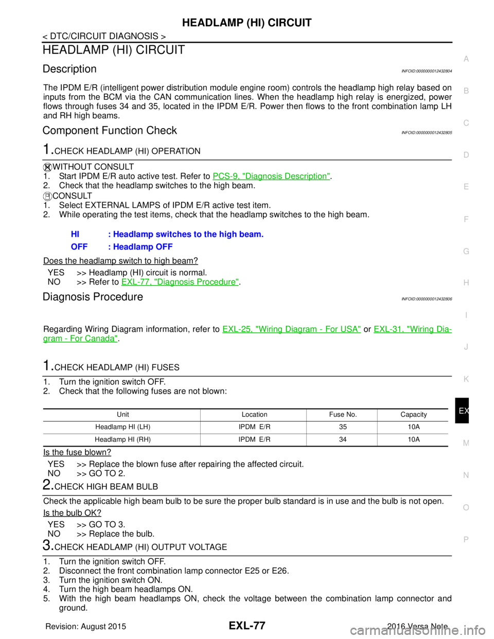
1.CHECK HEADLAMP (HI) FUSES
1. Turn the ignition switch OFF.
2. Check that the following fuses are not blown:
Is the fuse blown?
YES >> Replace the blown fuse after repairing the affected circuit.
NO >> GO TO 2.
2.CHECK HIGH BEAM BULB
Check the applicable high beam bulb to be sure the proper bulb standard is in use and the bulb is not open.
Is the bulb OK?
YES >> GO TO 3.
NO >> Replace the bulb.
3.CHECK HEADLAMP (HI) OUTPUT VOLTAGE
1. Turn the ignition switch OFF.
2. Disconnect the front combination lamp connector E25 or E26.
3. Turn the ignition switch ON.
4. Turn the high beam headlamps ON.
5. With the high beam headlamps ON, check the vo ltage between the combination lamp connector and
ground. HI : Headlamp switches to the high beam.
OFF : Headlamp OFF
Unit
LocationFuse No.Capacity
Headlamp HI (LH) IPDM E/R3510A
Headlamp HI (RH) IPDM E/R3410A
Revision: August 2015 2016 Versa Note
cardiagn.com
Page 1730 of 3641
EXL-78
< DTC/CIRCUIT DIAGNOSIS >
HEADLAMP (HI) CIRCUIT
Is the inspection result normal?
YES >> GO TO 5.
NO >> GO TO 4.
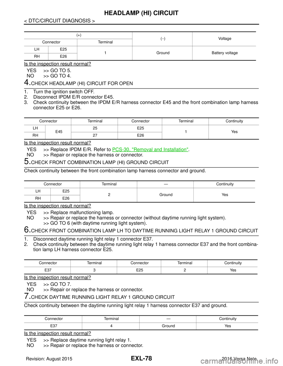
4.CHECK HEADLAMP (HI) CIRCUIT FOR OPEN
1. Turn the ignition switch OFF.
2. Disconnect IPDM E/R connector E45.
3. Check continuity between the IPDM E/R harness connector E45 and the front combination lamp harness connector E25 or E26.
Is the inspection result normal?
YES >> Replace IPDM E/R. Refer to PCS-30, "Removal and Installation".
NO >> Repair or replace the harness or connector.
5.CHECK FRONT COMBINATION LAMP (HI) GROUND CIRCUIT
Check continuity between the front combination lamp harness connector and ground.
Is the inspection result normal?
YES >> Replace malfunctioning lamp.
NO >> Repair or replace the harness or c onnector (without daytime running light system).
>> GO TO 6 (with daytime running light system).
6.CHECK FRONT COMBINATION LAMP LH TO DA YTIME RUNNING LIGHT RELAY 1 GROUND CIRCUIT
1. Disconnect daytime running light relay 1 connector E37.
2. Check continuity between the daytime running light relay 1 harness connector E37 and the front combina- tion lamp LH harness connector E25.
Is the inspection result normal?
YES >> GO TO 7.
NO >> Repair or replace the harness or connector.
7.CHECK DAYTIME RUNNING LIGHT RELAY 1 GROUND CIRCUIT
Check continuity between the daytime running light relay 1 harness connector E37 and ground.
Is the inspection result normal?
YES >> Replace daytime running light relay 1.
NO >> Repair or replace the harness or connector.
(+) (−)Voltage
Connector Terminal
LH E25
1 Ground Battery voltage
RH E26
Connector TerminalConnector Terminal Continuity
LH E45 25
E25
1Y es
RH 27E26
Connector Terminal —Continuity
LH E25
2G ro un dY es
RH E26
Connector TerminalConnector Terminal Continuity
E37 3E25 2Yes
Connector Terminal —Continuity
E37 4Ground Yes
Revision: August 2015 2016 Versa Note
cardiagn.com