NISSAN NOTE 2016 Service Repair Manual
Manufacturer: NISSAN, Model Year: 2016, Model line: NOTE, Model: NISSAN NOTE 2016Pages: 3641, PDF Size: 28.72 MB
Page 2331 of 3641
MA-16
< PERIODIC MAINTENANCE >
ENGINE MAINTENANCE
ENGINE COOLANT : Draining Engine Coolant
INFOID:0000000012432253
WARNING:
Do not remove the radiator cap when the engine is hot. Serious burns could occur from high-pressure
engine coolant escaping from the radiator. Wrap a th ick cloth around the cap. Slowly push down and
turn it a quarter turn to allow built-up pressure to escape. Carefully remove the cap by pushing it down
and turning it all the way.
1. Remove front under cover. Refer to EXT-39, "
FRONT UNDER COVER : Removal and Installation".
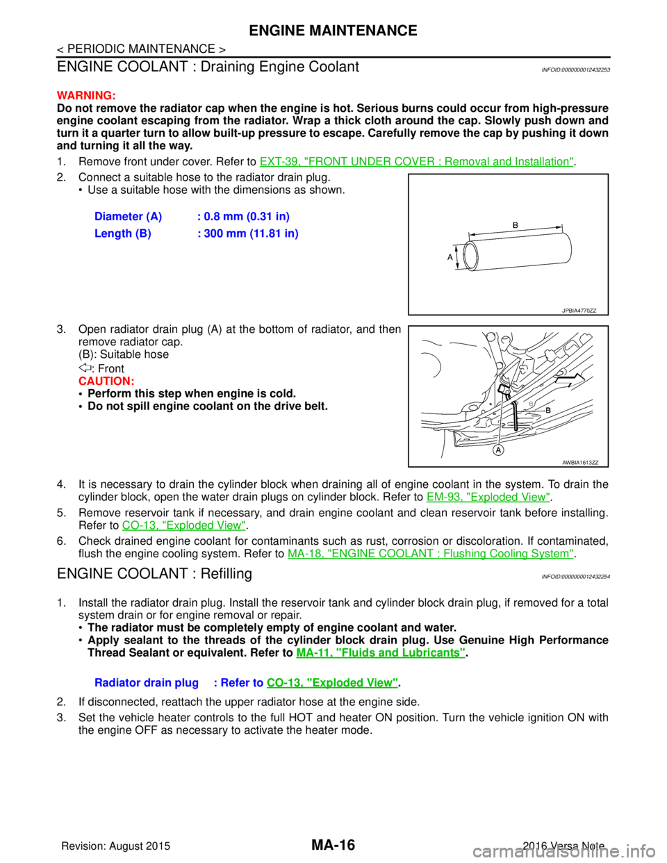
2. Connect a suitable hose to the radiator drain plug. • Use a suitable hose with the dimensions as shown.
3. Open radiator drain plug (A) at the bottom of radiator, and then remove radiator cap.
(B): Suitable hose
: Front
CAUTION:
• Perform this step when engine is cold.
• Do not spill engine coolant on the drive belt.
4. It is necessary to drain the cylinder block when drai ning all of engine coolant in the system. To drain the
cylinder block, open the water drain plugs on cylinder block. Refer to EM-93, "
Exploded View".
5. Remove reservoir tank if necessary, and drain engine coolant and clean reservoir tank before installing. Refer to CO-13, "
Exploded View".
6. Check drained engine coolant for contaminants such as rust, corrosion or discoloration. If contaminated, flush the engine cooling system. Refer to MA-18, "
ENGINE COOLANT : Flushing Cooling System".
ENGINE COOLANT : RefillingINFOID:0000000012432254
1. Install the radiator drain plug. Install the reservoir tank and cylinder block drain plug, if removed for a total
system drain or for engine removal or repair.
• The radiator must be completely empty of engine coolant and water.
• Apply sealant to the threads of the cylinder block drain plug. Use Genuine High Performance
Thread Sealant or equivalent. Refer to MA-11, "
Fluids and Lubricants".
2. If disconnected, reattach the upper radiator hose at the engine side.
3. Set the vehicle heater controls to the full HOT and heat er ON position. Turn the vehicle ignition ON with
the engine OFF as necessary to activate the heater mode. Diameter (A) : 0.8 mm (0.31 in)
Length (B) : 300 mm (11.81 in)
JPBIA4770ZZ
AWBIA1613ZZ
Radiator drain plug : Refer to
CO-13, "Exploded View".
Revision: August 2015 2016 Versa Note
cardiagn.com
Page 2332 of 3641
ENGINE MAINTENANCEMA-17
< PERIODIC MAINTENANCE >
C
DE
F
G H
I
J
K L
M B
MA
N
O A
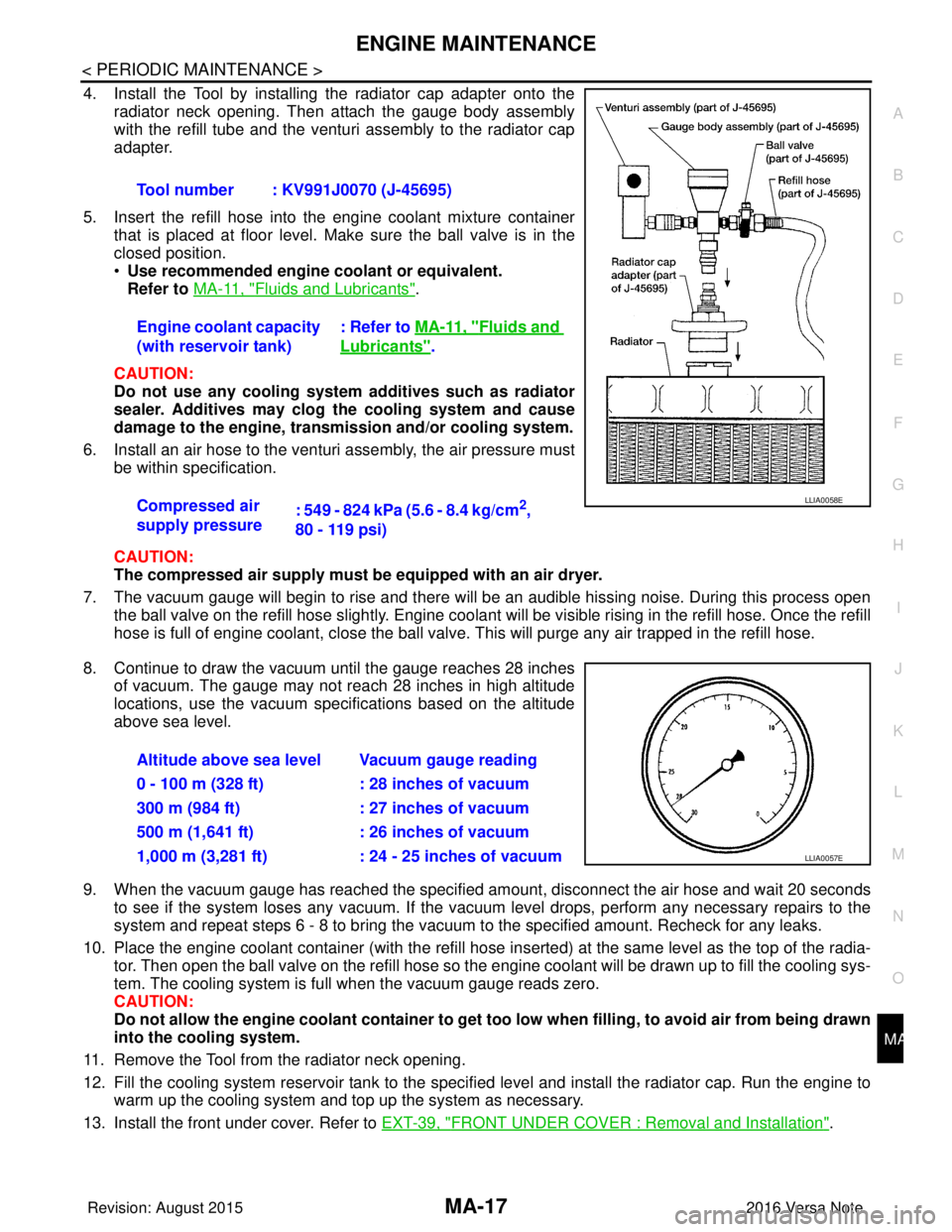
4. Install the Tool by installing the radiator cap adapter onto the
radiator neck opening. Then attach the gauge body assembly
with the refill tube and the venturi assembly to the radiator cap
adapter.
5. Insert the refill hose into the engine coolant mixture container that is placed at floor level. Make sure the ball valve is in the
closed position.
•Use recommended engine coolant or equivalent.
Refer to MA-11, "
Fluids and Lubricants".
CAUTION:
Do not use any cooling system additives such as radiator
sealer. Additives may clog the cooling system and cause
damage to the engine, transmission and/or cooling system.
6. Install an air hose to the venturi assembly, the air pressure must be within specification.
CAUTION:
The compressed air supply must be equipped with an air dryer.
7. The vacuum gauge will begin to rise and there will be an audible hissing noise. During this process open the ball valve on the refill hose slightly. Engine coolant will be visible rising in the refill hose. Once the refill
hose is full of engine coolant, close the ball valve. This will purge any air trapped in the refill hose.
8. Continue to draw the vacuum until the gauge reaches 28 inches of vacuum. The gauge may not reach 28 inches in high altitude
locations, use the vacuum specifications based on the altitude
above sea level.
9. When the vacuum gauge has reached the specified amount, disconnect the air hose and wait 20 seconds
to see if the system loses any vacuum. If the vacuum level drops, perform any necessary repairs to the
system and repeat steps 6 - 8 to br ing the vacuum to the specified amount. Recheck for any leaks.
10. Place the engine coolant container (with the refill hose in serted) at the same level as the top of the radia-
tor. Then open the ball valve on the refill hose so the engine coolant will be drawn up to fill the cooling sys-
tem. The cooling system is full when the vacuum gauge reads zero.
CAUTION:
Do not allow the engine coolant co ntainer to get too low when filling, to avoid air from being drawn
into the cooling system.
11. Remove the Tool from the radiator neck opening.
12. Fill the cooling system reservoir tank to the specif ied level and install the radiator cap. Run the engine to
warm up the cooling system and top up the system as necessary.
13. Install the front under cover. Refer to EXT-39, "
FRONT UNDER COVER : Removal and Installation".
Tool number : KV991J0070 (J-45695)
Engine coolant capacity
(with reservoir tank)
: Refer to
MA-11, "
Fluids and
Lubricants".
Compressed air
supply pressure : 549 - 824 kPa (5.6 - 8.4 kg/cm
2,
80 - 119 psi)LLIA0058E
Altitude above sea level Vacuum gauge reading
0 - 100 m (328 ft) : 28 inches of vacuum
300 m (984 ft) : 27 inches of vacuum
500 m (1,641 ft) : 26 inches of vacuum
1,000 m (3,281 ft) : 24 - 25 inches of vacuum
LLIA0057E
Revision: August 2015 2016 Versa Note
cardiagn.com
Page 2333 of 3641
MA-18
< PERIODIC MAINTENANCE >
ENGINE MAINTENANCE
ENGINE COOLANT : Flushing Cooling System
INFOID:0000000012432255
1. Install radiator drain plug and reservoir tank, if removed.
CAUTION:
Be sure to clean drain plug and install with new O-ring.
2. If water drain plugs on cylinder block were removed, close and tighten them. Refer to EM-93, "
Exploded
View".
3. Remove air duct from between air cleaner case and electric throttle control actuator. Refer to EM-26,
"Removal and Installation".
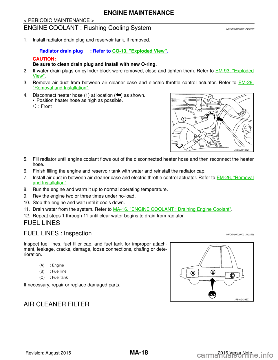
4. Disconnect heater hose (1) at location ( ) as shown. • Position heater hose as high as possible.
: Front
5. Fill radiator until engine coolant flows out of the disconnected heater hose and then reconnect the heater
hose.
6. Finish filling the engine and reservoir tank with water and reinstall the radiator cap.
7. Install air duct in between air cleaner case and electric throttle control actuator. Refer to EM-26, "
Removal
and Installation".
8. Run the engine and warm it up to normal operating temperature.
9. Rev the engine two or three times under no-load.
10. Stop the engine and wait until it cools down.
11. Drain water from the system. Refer to MA-16, "
ENGINE COOLANT : Draining Engine Coolant".
12. Repeat steps 1 through 11 until clear water begins to drain from radiator.
FUEL LINES
FUEL LINES : InspectionINFOID:0000000012432256
Inspect fuel lines, fuel filler cap, and fuel tank for improper attach-
ment, leakage, cracks, damage, l oose connections, chafing or dete-
rioration.
If necessary, repair or replace damaged parts.
AIR CLEANER FILTER
Radiator drain plug : Refer to CO-13, "Exploded View".
JSBIA0616ZZ
(A) : Engine
(B) : Fuel line
(C) : Fuel tank
JPBIA0129ZZ
Revision: August 2015 2016 Versa Note
cardiagn.com
Page 2334 of 3641
ENGINE MAINTENANCEMA-19
< PERIODIC MAINTENANCE >
C
DE
F
G H
I
J
K L
M B
MA
N
O A
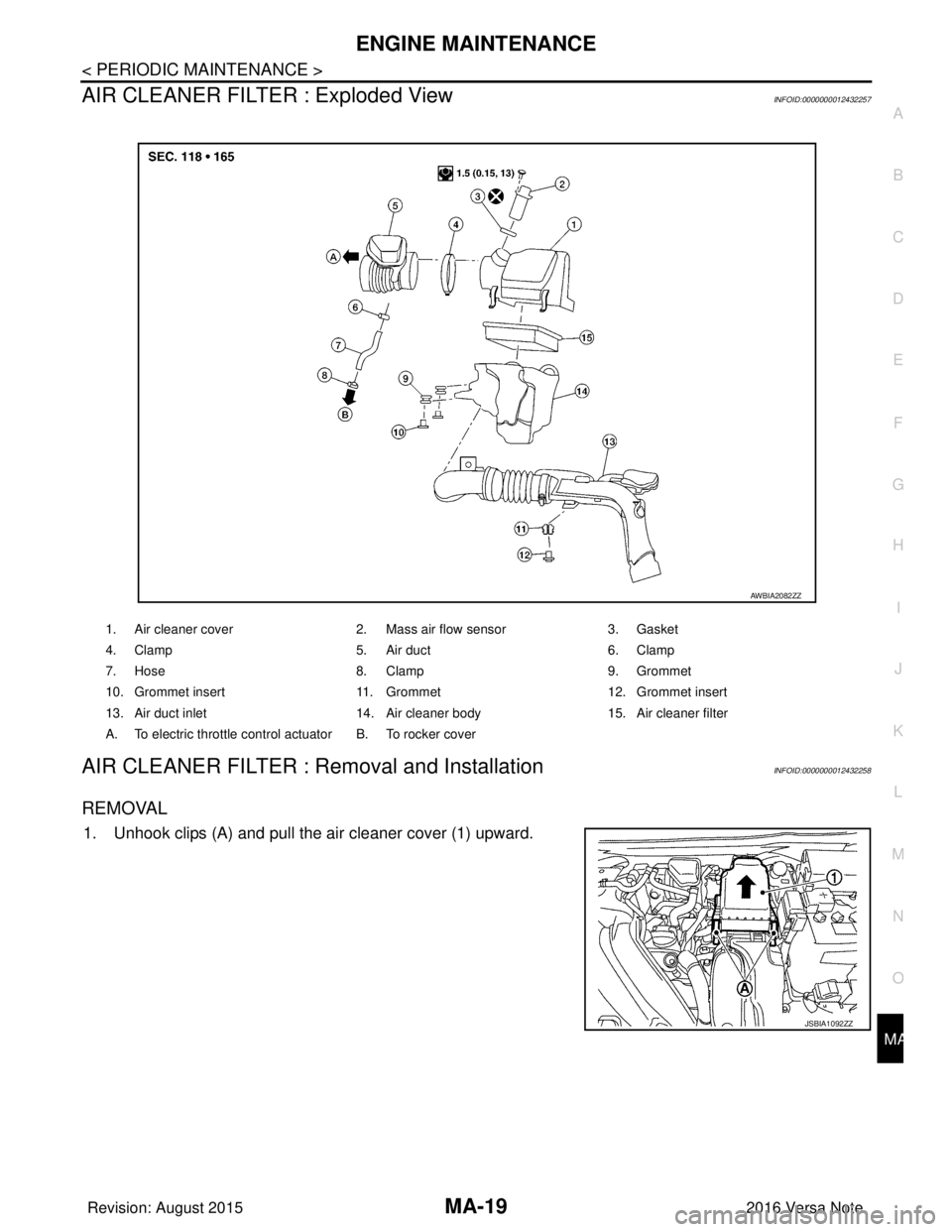
AIR CLEANER FILTER : Exploded ViewINFOID:0000000012432257
AIR CLEANER FILTER : Removal and InstallationINFOID:0000000012432258
REMOVAL
1. Unhook clips (A) and pull the air cleaner cover (1) upward.
1. Air cleaner cover
2. Mass air flow sensor 3. Gasket
4. Clamp 5. Air duct 6. Clamp
7. Hose 8. Clamp 9. Grommet
10. Grommet insert 11. Grommet 12. Grommet insert
13. Air duct inlet 14. Air cleaner body 15. Air cleaner filter
A. To electric throttle contro l actuator B. To rocker cover
AWBIA2082ZZ
JSBIA1092ZZ
Revision: August 2015 2016 Versa Note
cardiagn.com
Page 2335 of 3641
MA-20
< PERIODIC MAINTENANCE >
ENGINE MAINTENANCE
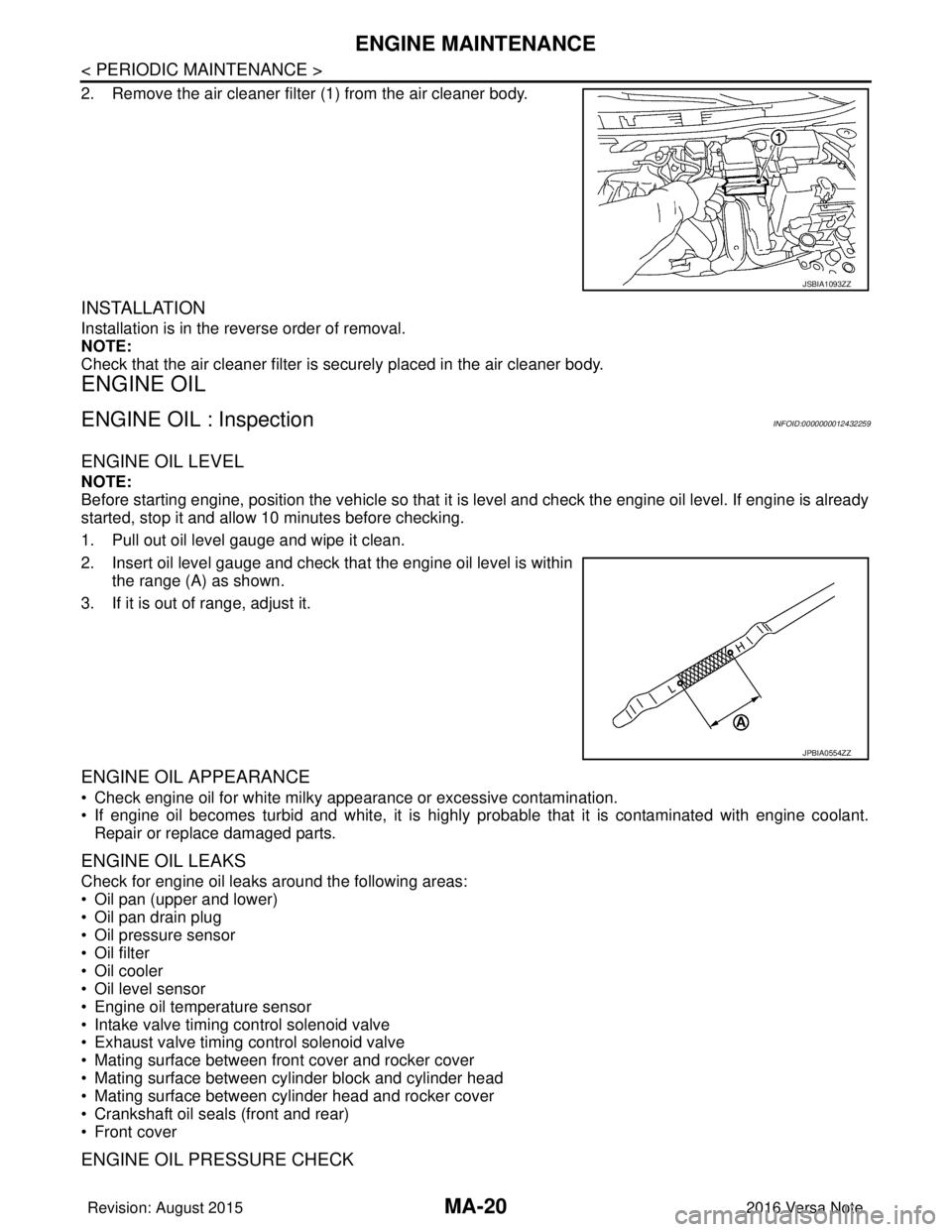
2. Remove the air cleaner filter (1) from the air cleaner body.
INSTALLATION
Installation is in the reverse order of removal.
NOTE:
Check that the air cleaner filter is securely placed in the air cleaner body.
ENGINE OIL
ENGINE OIL : InspectionINFOID:0000000012432259
ENGINE OIL LEVEL
NOTE:
Before starting engine, position the vehicle so that it is level and check the engine oil level. If engine is already
started, stop it and allow 10 minutes before checking.
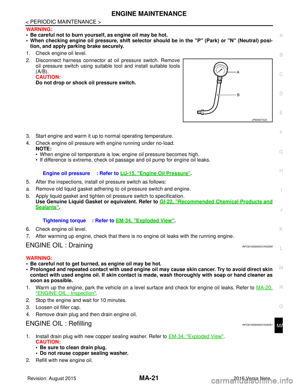
1. Pull out oil level gauge and wipe it clean.
2. Insert oil level gauge and check that the engine oil level is withinthe range (A) as shown.
3. If it is out of range, adjust it.
ENGINE OIL APPEARANCE
• Check engine oil for white milky appearance or excessive contamination.
• If engine oil becomes turbid and white, it is highl y probable that it is contaminated with engine coolant.
Repair or replace damaged parts.
ENGINE OIL LEAKS
Check for engine oil leaks around the following areas:
• Oil pan (upper and lower)
• Oil pan drain plug
• Oil pressure sensor
• Oil filter
• Oil cooler
• Oil level sensor
• Engine oil temperature sensor
• Intake valve timing control solenoid valve
• Exhaust valve timing control solenoid valve
• Mating surface between front cover and rocker cover
• Mating surface between cylinder block and cylinder head
• Mating surface between cylinder head and rocker cover
• Crankshaft oil seals (front and rear)
• Front cover
ENGINE OIL PRESSURE CHECK
JSBIA1093ZZ
JPBIA0554ZZ
Revision: August 2015 2016 Versa Note
cardiagn.com
Page 2336 of 3641
ENGINE MAINTENANCEMA-21
< PERIODIC MAINTENANCE >
C
DE
F
G H
I
J
K L
M B
MA
N
O A
WARNING:
• Be careful not to burn yoursel
f, as engine oil may be hot.
• When checking engine oil pressure, sh ift selector should be in the "P" (Park) or "N" (Neutral) posi-
tion, and apply parking brake securely.
1. Check engine oil level.
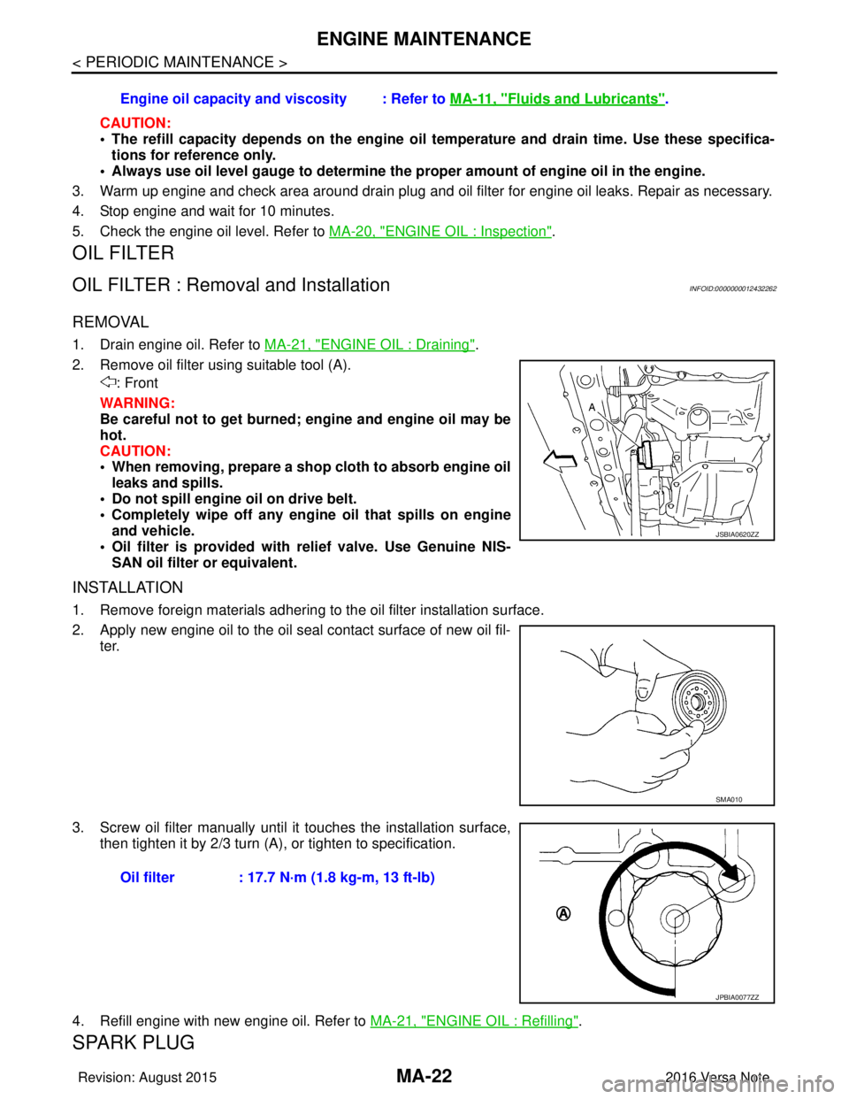
2. Disconnect harness connector at oil pressure switch. Remove oil pressure switch using suitable tool and install suitable tools
(A/B).
CAUTION:
Do not drop or shock oil pressure switch.
3. Start engine and warm it up to normal operating temperature.
4. Check engine oil pressure with engine running under no-load. NOTE:
• When engine oil temperature is low, engine oil pressure becomes high.
• If difference is extreme, check oil passage and oil pump for engine oil leaks.
5. After the inspections, install oil pressure switch as follows:
a. Remove old liquid gasket adhering to oil pressure switch and engine.
b. Apply liquid gasket and tighten oil pressure switch to specification. Use Genuine Liquid Gasket or equivalent. Refer to GI-22, "
Recommended Chemical Products and
Sealants".
6. Check engine oil level.
7. After warming up engine, check that there is no engine oil leaks with the running engine.
ENGINE OIL : DrainingINFOID:0000000012432260
WARNING:
• Be careful not to get burned, as engine oil may be hot.
• Prolonged and repeated contact with used engine oil may cause skin cancer. Try to avoid direct skin
contact with used engine oil. If skin contact is made, wash thorough ly with soap or hand cleaner as
soon as possible.
1. Warm up the engine, park the vehicle on a level surface and check for engine oil leaks. Refer to MA-20,
"ENGINE OIL : Inspection".
2. Stop the engine and wait for 10 minutes.
3. Loosen oil filler cap.
4. Remove drain plug and then drain engine oil.
ENGINE OIL : RefillingINFOID:0000000012432261
1. Install drain plug with new copper sealing washer. Refer to EM-34, "Exploded View".
CAUTION:
• Be sure to clean drain plug.
• Do not reuse copper sealing washer.
2. Refill with new engine oil.
JPBIA0074ZZ
Engine oil pressure : Refer to LU-15, "Engine Oil Pressure".
Tightening torque : Refer to EM-34, "
Exploded View".
Revision: August 2015 2016 Versa Note
cardiagn.com
Page 2337 of 3641
MA-22
< PERIODIC MAINTENANCE >
ENGINE MAINTENANCE
CAUTION:
• The refill capacity depends on the engine oil temperature and drain time. Use these specifica-
tions for reference only.
• Always use oil level gauge to determine the pr oper amount of engine oil in the engine.
3. Warm up engine and check area around drain plug and oil filter for engine oil leaks. Repair as necessary.
4. Stop engine and wait for 10 minutes.
5. Check the engine oil level. Refer to MA-20, "
ENGINE OIL : Inspection".
OIL FILTER
OIL FILTER : Removal and InstallationINFOID:0000000012432262
REMOVAL
1. Drain engine oil. Refer to MA-21, "ENGINE OIL : Draining".
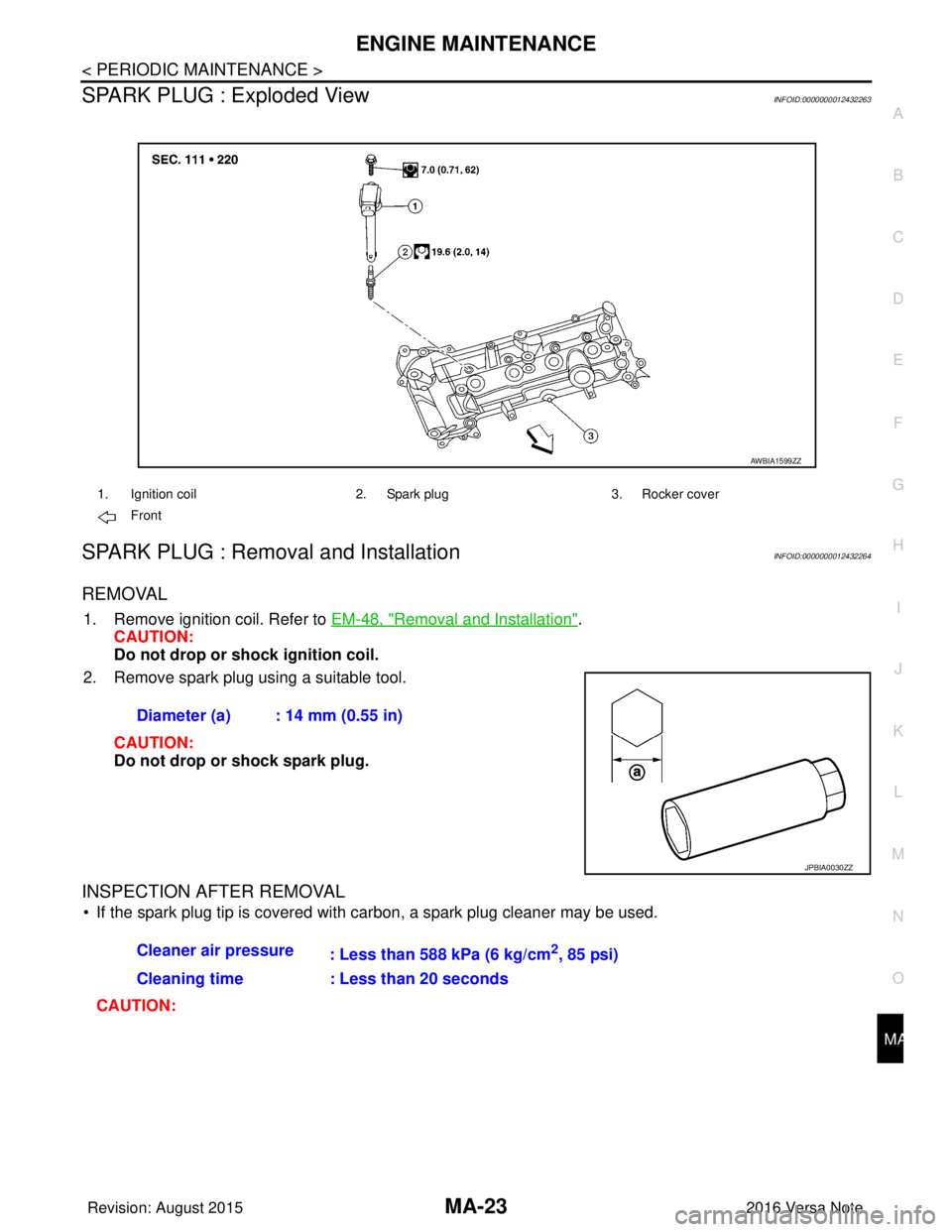
2. Remove oil filter using suitable tool (A). : Front
WARNING:
Be careful not to get burned; engine and engine oil may be
hot.
CAUTION:
• When removing, prepare a shop cloth to absorb engine oil leaks and spills.
• Do not spill engine oil on drive belt.
• Completely wipe off any engine oil that spills on engine
and vehicle.
• Oil filter is provided with relief valve. Use Genuine NIS- SAN oil filter or equivalent.
INSTALLATION
1. Remove foreign materials adhering to the oil filter installation surface.
2. Apply new engine oil to the oil seal contact surface of new oil fil- ter.
3. Screw oil filter manually until it touches the installation surface,
then tighten it by 2/3 turn (A), or tighten to specification.
4. Refill engine with new engine oil. Refer to MA-21, "
ENGINE OIL : Refilling".
SPARK PLUG
Engine oil capacity and viscosity : Refer to MA-11, "Fluids and Lubricants".
JSBIA0620ZZ
SMA010
Oil filter : 17.7 N·m (1.8 kg-m, 13 ft-lb)
JPBIA0077ZZ
Revision: August 2015 2016 Versa Note
cardiagn.com
Page 2338 of 3641
ENGINE MAINTENANCEMA-23
< PERIODIC MAINTENANCE >
C
DE
F
G H
I
J
K L
M B
MA
N
O A
SPARK PLUG : Exploded ViewINFOID:0000000012432263
SPARK PLUG : Removal and InstallationINFOID:0000000012432264
REMOVAL
1. Remove ignition coil. Refer to
EM-48, "Removal and Installation".
CAUTION:
Do not drop or shock ignition coil.
2. Remove spark plug using a suitable tool.
CAUTION:
Do not drop or shock spark plug.
INSPECTION AFTER REMOVAL
• If the spark plug tip is covered with carbon, a spark plug cleaner may be used.
CAUTION:
1. Ignition coil 2. Spark plug3. Rocker cover
Front
AWBIA1599ZZ
Diameter (a) : 14 mm (0.55 in)
JPBIA0030ZZ
Cleaner air pressure : Less than 588 kPa (6 kg/cm2, 85 psi)
Cleaning time : Less than 20 seconds
Revision: August 2015 2016 Versa Note
cardiagn.com
Page 2339 of 3641
MA-24
< PERIODIC MAINTENANCE >
ENGINE MAINTENANCE
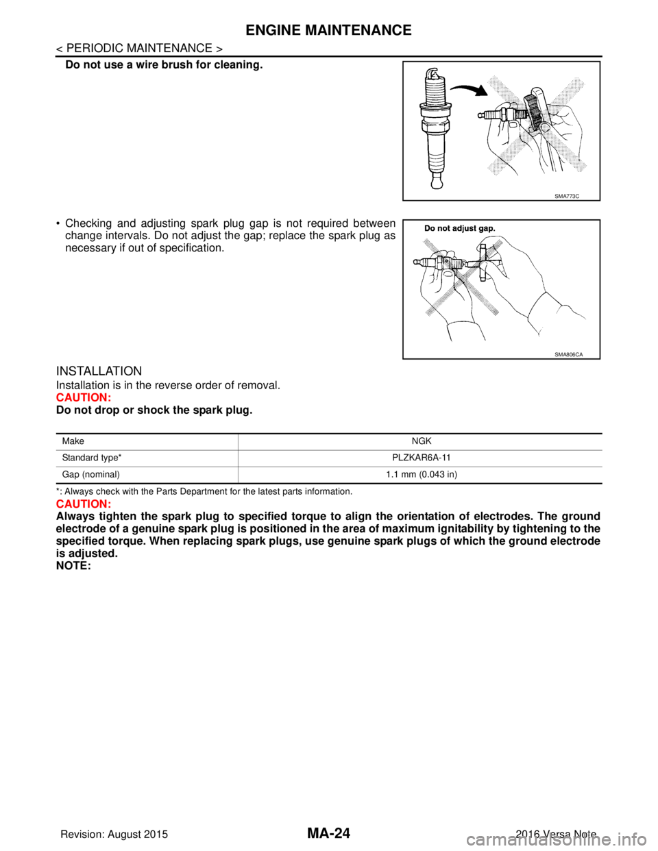
Do not use a wire brush for cleaning.
• Checking and adjusting spark plug gap is not required between change intervals. Do not adjust the gap; replace the spark plug as
necessary if out of specification.
INSTALLATION
Installation is in the reverse order of removal.
CAUTION:
Do not drop or shock the spark plug.
*: Always check with the Parts Department for the latest parts information.
CAUTION:
Always tighten the spark plug to specified torque to align the orie ntation of electrodes. The ground
electrode of a genuine spark plug is positioned in the area of maximum ignitability by tightening to the
specified torque. When replacing spark plugs, use genuine spark pl ugs of which the ground electrode
is adjusted.
NOTE:
SMA773C
SMA806CA
Make NGK
Standard type* PLZKAR6A-11
Gap (nominal) 1.1 mm (0.043 in)
Revision: August 2015 2016 Versa Note
cardiagn.com
Page 2340 of 3641
ENGINE MAINTENANCEMA-25
< PERIODIC MAINTENANCE >
C
DE
F
G H
I
J
K L
M B
MA
N
O A
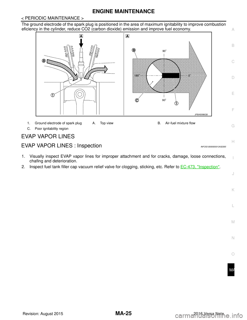
The ground electrode of the spark plug is positioned in the area of maximum ignitability to improve combustion
eficiency in the cylinder, reduce CO2 (carbon
dioxide) emission and improve fuel economy.
EVAP VAPOR LINES
EVAP VAPOR LINES : InspectionINFOID:0000000012432265
1. Visually inspect EVAP vapor lines for improper attachment and for cracks, damage, loose connections,
chafing and deterioration.
2. Inspect fuel tank filler cap vacuum relie f valve for clogging, sticking, etc. Refer to EC-473, "
Inspection".
1. Ground electrode of spark plug A. Top view B. Air-fuel mixture flow
C. Poor ignitability region
JPBIA5996GB
Revision: August 2015 2016 Versa Note
cardiagn.com