NISSAN NOTE 2016 Service Repair Manual
Manufacturer: NISSAN, Model Year: 2016,
Model line: NOTE,
Model: NISSAN NOTE 2016
Pages: 3641, PDF Size: 28.72 MB
NISSAN NOTE 2016 Service Repair Manual
NOTE 2016
NISSAN
NISSAN
https://www.carmanualsonline.info/img/5/57363/w960_57363-0.png
NISSAN NOTE 2016 Service Repair Manual
Trending: wiper blades, snow chains, mileage, display, open gas tank, diagnostic menu, turn signal bulb
Page 601 of 3641

CHG-6
< SYSTEM DESCRIPTION >
COMPONENT PARTS
Component Description
INFOID:0000000012431240
No. Component part Description
1 IPDM E/R The IPDM E/R converts the received power generation com-
mand value into a pulse width modulated (PWM) command sig-
nal and sends it to the IC regulator.
2ECM The battery current sensor detects the charging/discharging
current of the battery. The ECM judges the battery condition
based on this signal.
The ECM judges whether to request more output via the power
generation voltage variable control according to the battery
condition.
When performing the power generation voltage variable con-
trol, the ECM calculates the target power generation voltage
according to the battery condition and sends the calculated val-
ue as the power generation command value to the IPDM E/R.
3 Battery current sensor The battery current sensor is located on the negative battery
cable terminal. The battery current sensor detects the charg-
ing/discharging current of the battery and sends a voltage sig-
nal to the ECM according to the current value detected.
4 Generator (IC regulator) The IC regulator controls the power generation voltage by the
target power generation voltage based on the received PWM
command signal.
When there is no PWM command signal, the generator per-
forms the normal power generation according to the character-
istic of the IC regulator.
5 Combination meter (charge warning lamp) The IC regulator warning function activates to illuminate the
charge warning lamp if any of the following symptoms occur
while generator is operating:
• Excessive voltage is produced.
• No voltage is produced.
Revision: August 2015
2016 Versa Note
cardiagn.com
Page 602 of 3641
CHG
SYSTEMCHG-7
< SYSTEM DESCRIPTION >
C
DE
F
G H
I
J
K L
B A
O P
N
SYSTEM
CHARGING SYSTEM
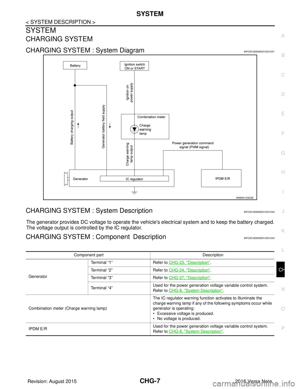
CHARGING SYSTEM : System DiagramINFOID:0000000012431241
CHARGING SYSTEM : System DescriptionINFOID:0000000012431242
The generator provides DC voltage to operate the vehicl
e's electrical system and to keep the battery charged.
The voltage output is controlled by the IC regulator.
CHARGING SYSTEM : Component DescriptionINFOID:0000000012431243
AWMIA1334GB
Component part Description
Generator Terminal “1”
Refer to CHG-23, "
Description".
Terminal “2” Refer to CHG-24, "
Description".
Terminal “3” Refer to CHG-27, "
Description".
Terminal “4” Used for the power generation voltage variable control system.
Refer to CHG-8, "
System Description".
Combination meter (C harge warning lamp) The IC regulator warning function activates to illuminate the
charge warning lamp if any of the following symptoms occur while
generator is operating:
• Excessive voltage is produced.
• No voltage is produced.
IPDM E/R Used for the power generation voltage variable control system.
Refer to CHG-8, "
System Description".
Revision: August 2015
2016 Versa Note
cardiagn.com
Page 603 of 3641
CHG-8
< SYSTEM DESCRIPTION >
POWER GENERATION VOLTAGE VARIABLE CONTROL SYSTEM
POWER GENERATION VOLTAGE VARIABLE CONTROL SYSTEM
System DiagramINFOID:0000000012431244
System DescriptionINFOID:0000000012431245
Power generation variable voltage control system has been adopted. By varying the voltage to the generator,
engine load due to power generation of the generator is reduced and fuel consumption is decreased.
NOTE:
When any malfunction is detected in the power generation variable voltage control system, power generation
is performed according to the characteristic of the IC regulator in the generator.
ALMIA0566GB
Revision: August 2015 2016 Versa Note
cardiagn.com
Page 604 of 3641
CHG
CHARGING SYSTEMCHG-9
< WIRING DIAGRAM >
C
DE
F
G H
I
J
K L
B A
O P
N
WIRING DIAGRAM
CHARGING SYSTEM
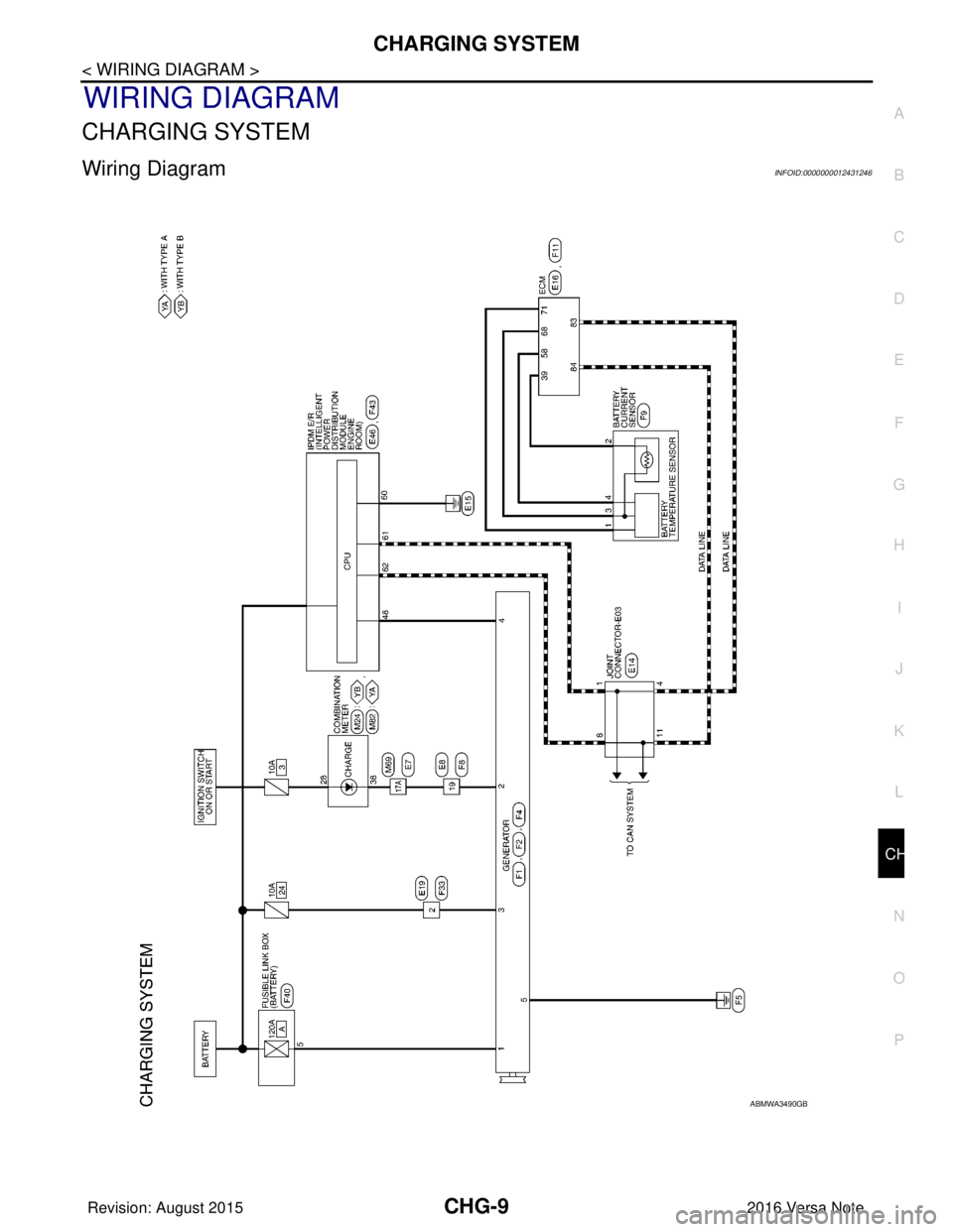
Wiring DiagramINFOID:0000000012431246
ABMWA3490GB
Revision: August 2015
2016 Versa Note
cardiagn.com
Page 605 of 3641
CHG-10
< WIRING DIAGRAM >
CHARGING SYSTEM
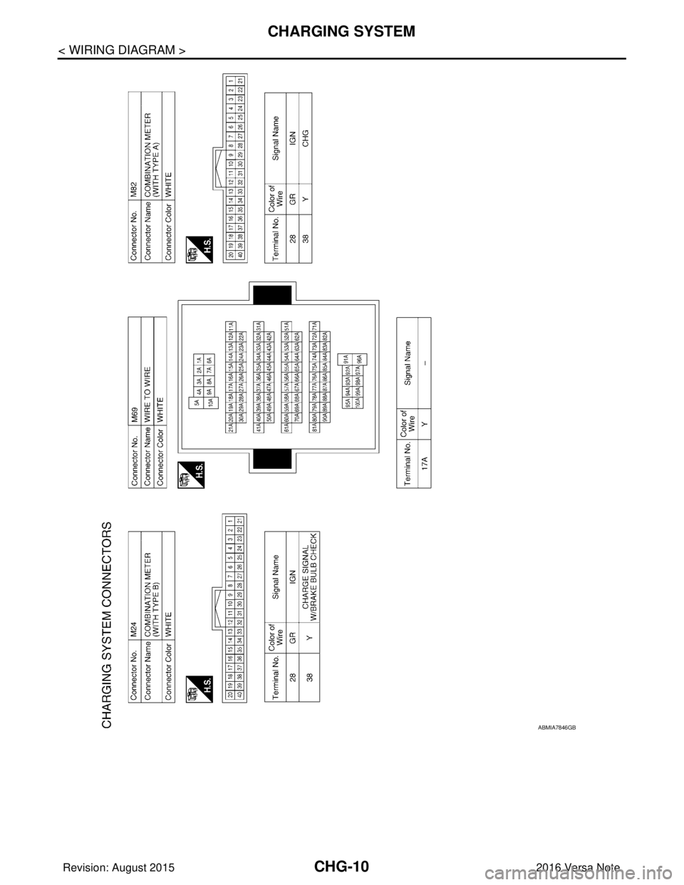
ABMIA7846GB
Revision: August 20152016 Versa Note
cardiagn.com
Page 606 of 3641
CHG
CHARGING SYSTEMCHG-11
< WIRING DIAGRAM >
C
DE
F
G H
I
J
K L
B A
O P
N
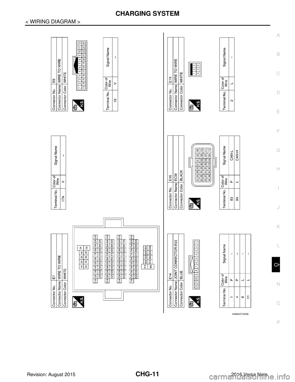
AAMIA2732GB
Revision: August 2015
2016 Versa Note
cardiagn.com
Page 607 of 3641
CHG-12
< WIRING DIAGRAM >
CHARGING SYSTEM
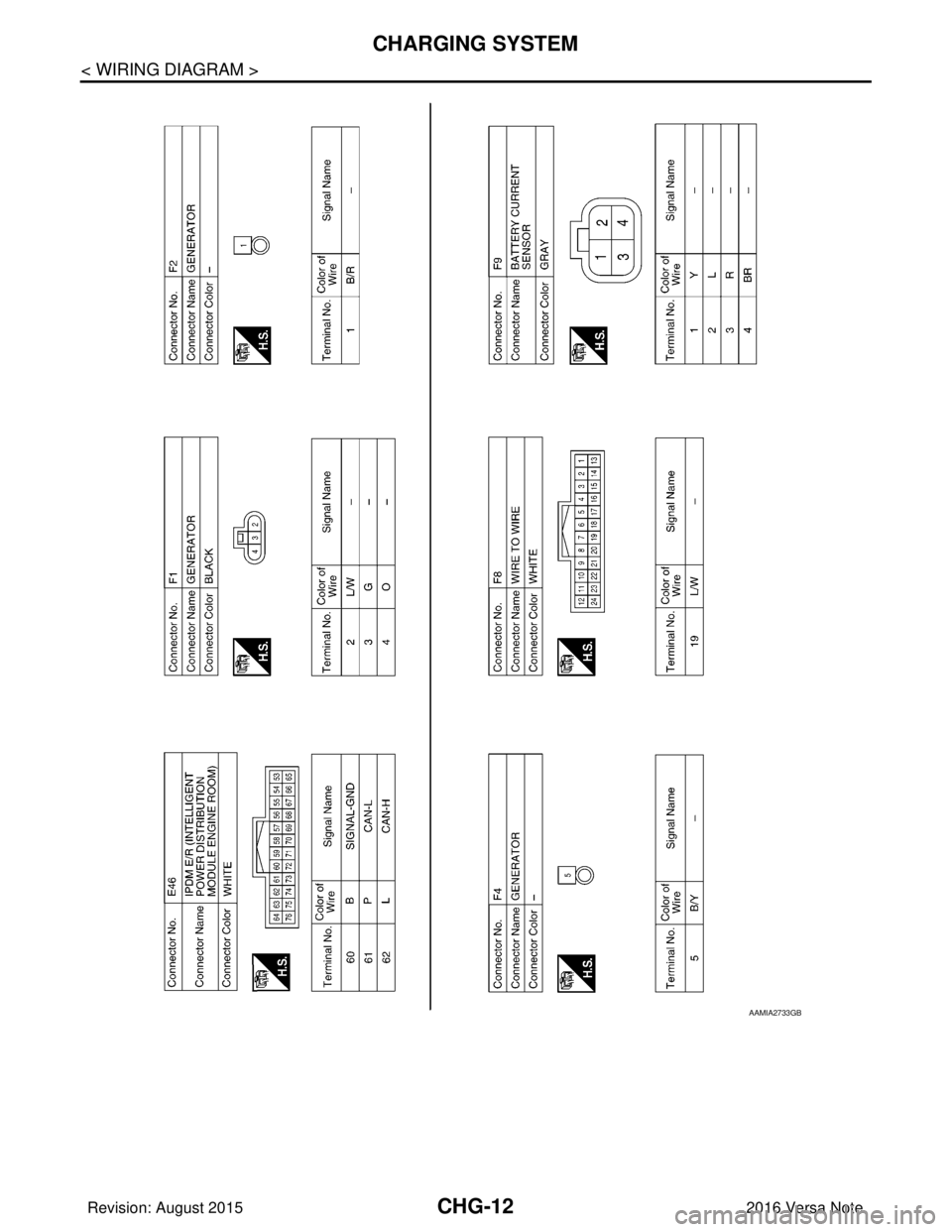
AAMIA2733GB
Revision: August 20152016 Versa Note
cardiagn.com
Page 608 of 3641
CHG
CHARGING SYSTEMCHG-13
< WIRING DIAGRAM >
C
DE
F
G H
I
J
K L
B A
O P
N
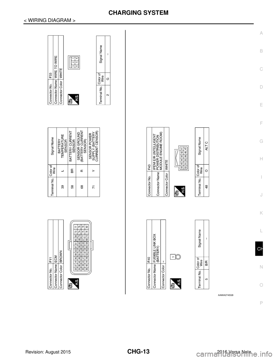
AAMIA2745GB
Revision: August 2015
2016 Versa Note
cardiagn.com
Page 609 of 3641
CHG-14
< BASIC INSPECTION >
DIAGNOSIS AND REPAIR WORKFLOW
BASIC INSPECTION
DIAGNOSIS AND REPAIR WORKFLOW
Work Flow (With EXP-800 NI or GR8-1200 NI)INFOID:0000000012431247
CHARGING SYSTEM DIAGNOSIS WITH EXP-800 NI OR GR8-1200 NI
To test the charging system, use the following special service tools:
• EXP-800 NI Battery and electrical diagnostic analyzer
• GR8-1200 NI Multitasking battery and electrical diagnostic station
NOTE:
Refer to the applicable Instruction Manual fo r proper charging system diagnosis procedures.
Revision: August 2015 2016 Versa Note
cardiagn.com
Page 610 of 3641
CHG
DIAGNOSIS AND REPAIR WORKFLOWCHG-15
< BASIC INSPECTION >
C
DE
F
G H
I
J
K L
B A
O P
N
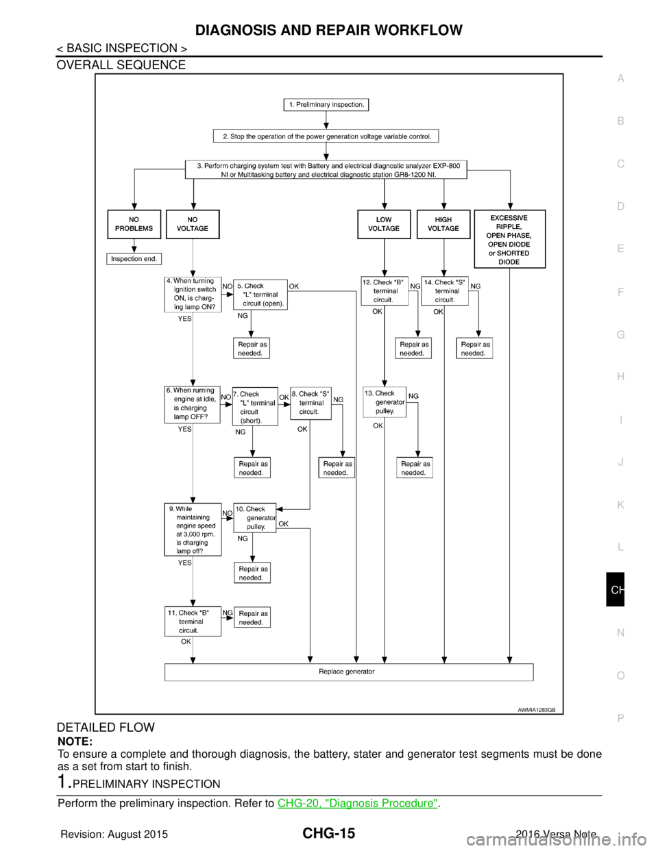
OVERALL SEQUENCE
DETAILED FLOW
NOTE:
To ensure a complete and thorough diagnosis, the batte
ry, stater and generator test segments must be done
as a set from start to finish.
1.PRELIMINARY INSPECTION
Perform the preliminary inspection. Refer to CHG-20, "
Diagnosis Procedure".
AWMIA1283GB
Revision: August 2015 2016 Versa Note
cardiagn.com
Trending: brake light, AUX, key fob battery, air conditioning, battery location, jacking points, power steering fluid


