NISSAN NOTE 2016 Service Repair Manual
Manufacturer: NISSAN, Model Year: 2016, Model line: NOTE, Model: NISSAN NOTE 2016Pages: 3641, PDF Size: 28.72 MB
Page 641 of 3641
CLUTCH PIPINGCL-15
< REMOVAL AND INSTALLATION >
CEF
G H
I
J
K L
M A
B
CL
N
O P
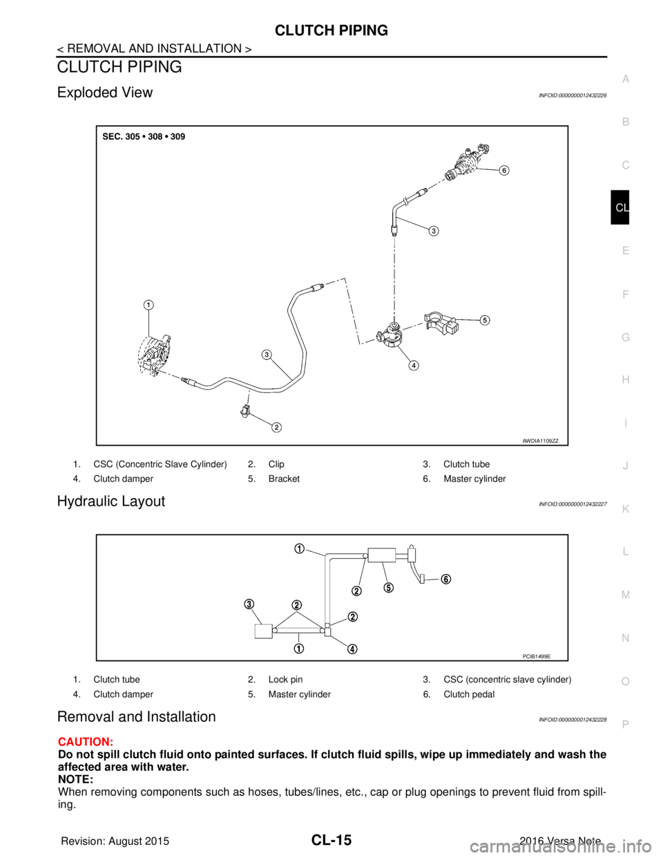
CLUTCH PIPING
Exploded ViewINFOID:0000000012432226
Hydraulic LayoutINFOID:0000000012432227
Removal and InstallationINFOID:0000000012432228
CAUTION:
Do not spill clutch fluid onto painted surfaces. If clutch fluid spills, wipe up immediately and wash the
affected area with water.
NOTE:
When removing components such as hoses, tubes/lines, etc. , cap or plug openings to prevent fluid from spill-
ing.
1. CSC (Concentric Slave Cylinder) 2. Clip 3. Clutch tube
4. Clutch damper 5. Bracket6. Master cylinder
AWDIA1109ZZ
1. Clutch tube 2. Lock pin3. CSC (concentric slave cylinder)
4. Clutch damper 5. Master cylinder6. Clutch pedal
PCIB1499E
Revision: August 2015 2016 Versa Note
cardiagn.com
Page 642 of 3641
CL-16
< REMOVAL AND INSTALLATION >
CLUTCH PIPING
REMOVAL
1. Remove the battery. Refer to PG-70, "Removal and Installation (Battery)".
2. Use one of the following methods to remove hose from clutch master cylinder. • Drain clutch fluid from reservoir tank and remove hose. Refer to CL-7, "
Draining".
• Remove hose from clutch master cylinder.
3. Remove clutch tube lock pin from clutch master cylinder.
4. Remove clutch tube lock pin at clutch housing.
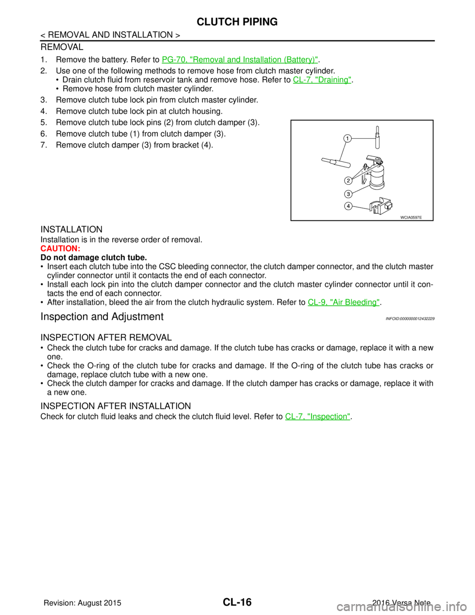
5. Remove clutch tube lock pins (2) from clutch damper (3).
6. Remove clutch tube (1) from clutch damper (3).
7. Remove clutch damper (3) from bracket (4).
INSTALLATION
Installation is in the reverse order of removal.
CAUTION:
Do not damage clutch tube.
• Insert each clutch tube into the CSC bleeding connector, the clutch damper connector, and the clutch master cylinder connector until it contacts the end of each connector.
• Install each lock pin into the clutch damper connecto r and the clutch master cylinder connector until it con-
tacts the end of each connector.
• After installation, bleed the air from the clutch hydraulic system. Refer to CL-9, "
Air Bleeding".
Inspection and AdjustmentINFOID:0000000012432229
INSPECTION AFTER REMOVAL
• Check the clutch tube for cracks and damage. If the cl utch tube has cracks or damage, replace it with a new
one.
• Check the O-ring of the clutch tube for cracks and dam age. If the O-ring of the clutch tube has cracks or
damage, replace clutch tube with a new one.
• Check the clutch damper for cracks and damage. If the clutch damper has cracks or damage, replace it with
a new one.
INSPECTION AFTER INSTALLATION
Check for clutch fluid leaks and check the clutch fluid level. Refer to CL-7, "Inspection".
WCIA0597E
Revision: August 2015 2016 Versa Note
cardiagn.com
Page 643 of 3641
CSC (CONCENTRIC SLAVE CYLINDER)CL-17
< UNIT REMOVAL AND INSTALLATION >
CEF
G H
I
J
K L
M A
B
CL
N
O P
UNIT REMOVAL AND INSTALLATION
CSC (CONCENTRIC SLAVE CYLINDER)
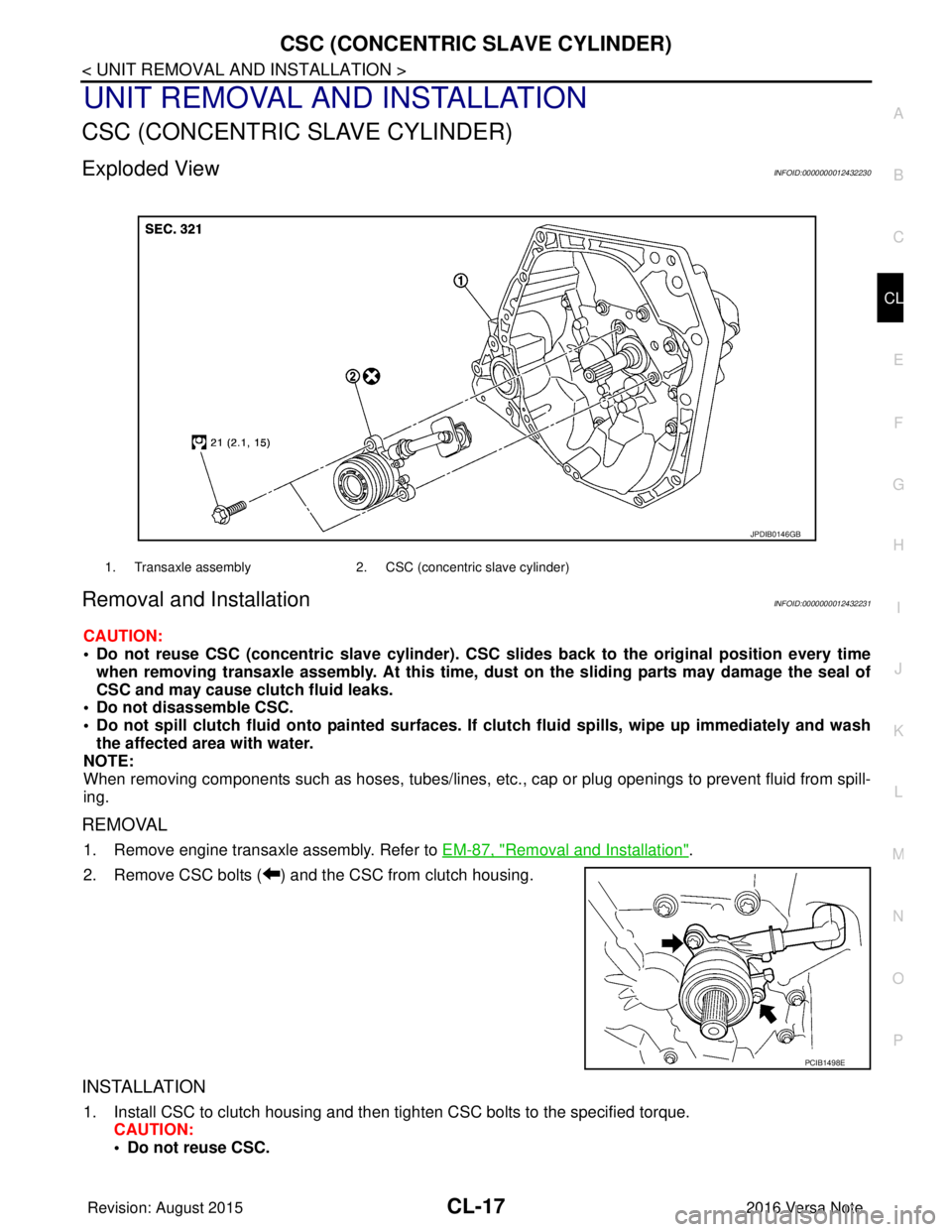
Exploded ViewINFOID:0000000012432230
Removal and InstallationINFOID:0000000012432231
CAUTION:
• Do not reuse CSC (concentric slave cylinder). CSC slides back to the original position every time
when removing transaxle assembly. At this time, du st on the sliding parts may damage the seal of
CSC and may cause clutch fluid leaks.
• Do not disassemble CSC.
• Do not spill clutch fluid onto pa inted surfaces. If clutch fluid spills, wipe up immediately and wash
the affected area with water.
NOTE:
When removing components such as hoses, tubes/lines, etc. , cap or plug openings to prevent fluid from spill-
ing.
REMOVAL
1. Remove engine transaxle assembly. Refer to EM-87, "Removal and Installation".
2. Remove CSC bolts ( ) and the CSC from clutch housing.
INSTALLATION
1. Install CSC to clutch housing and then tighten CSC bolts to the specified torque. CAUTION:
• Do not reuse CSC.
1. Transaxle assembly 2. CSC (concentric slave cylinder)
JPDIB0146GB
PCIB1498E
Revision: August 2015 2016 Versa Note
cardiagn.com
Page 644 of 3641
CL-18
< UNIT REMOVAL AND INSTALLATION >
CSC (CONCENTRIC SLAVE CYLINDER)
• Do not insert and operate CSC when transaxle is removed. Piston and stopper of CSC compo-nents may fall off.
2. Install engine and transaxle assembly. Refer to EM-87, "
Removal and Installation".
Inspection and AdjustmentINFOID:0000000012432232
INSPECTION AFTER INSTALLATION
Check for clutch fluid leaks and clutch fluid level. Refer to CL-7, "Inspection".
ADJUSTMENT AFTER INSTALLATION
Perform the air bleeding. Refer to CL-9, "Air Bleeding".
Revision: August 2015 2016 Versa Note
cardiagn.com
Page 645 of 3641
CLUTCH DISC AND CLUTCH COVERCL-19
< UNIT REMOVAL AND INSTALLATION >
CEF
G H
I
J
K L
M A
B
CL
N
O P
CLUTCH DISC AND CLUTCH COVER
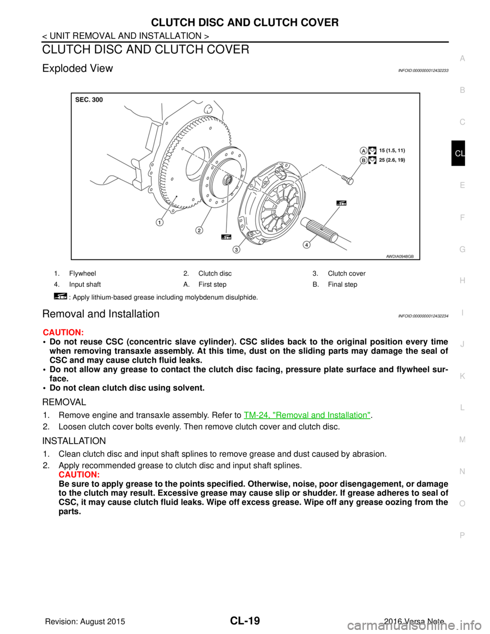
Exploded ViewINFOID:0000000012432233
Removal and InstallationINFOID:0000000012432234
CAUTION:
• Do not reuse CSC (concentric slave cylinder). CSC slides back to the original position every time
when removing transaxle assembly. At this time, du st on the sliding parts may damage the seal of
CSC and may cause clutch fluid leaks.
• Do not allow any grease to contact the clutch di sc facing, pressure plate surface and flywheel sur-
face.
• Do not clean clutch disc using solvent.
REMOVAL
1. Remove engine and transaxle assembly. Refer to TM-24, "Removal and Installation".
2. Loosen clutch cover bolts evenly. Then remove clutch cover and clutch disc.
INSTALLATION
1. Clean clutch disc and input shaft splines to remove grease and dust caused by abrasion.
2. Apply recommended grease to clutch disc and input shaft splines. CAUTION:
Be sure to apply grease to the points specified. Otherwise, noise, poor disengagement, or damage
to the clutch may result. Excessi ve grease may cause slip or shudder. If grease adheres to seal of
CSC, it may cause clutch fluid leaks. Wipe off excess grease. Wipe off any grease oozing from the
parts.
1. Flywheel 2. Clutch disc3. Clutch cover
4. Input shaft A. First stepB. Final step
: Apply lithium-based grease including molybdenum disulphide.
AWDIA0948GB
Revision: August 2015 2016 Versa Note
cardiagn.com
Page 646 of 3641
CL-20
< UNIT REMOVAL AND INSTALLATION >
CLUTCH DISC AND CLUTCH COVER
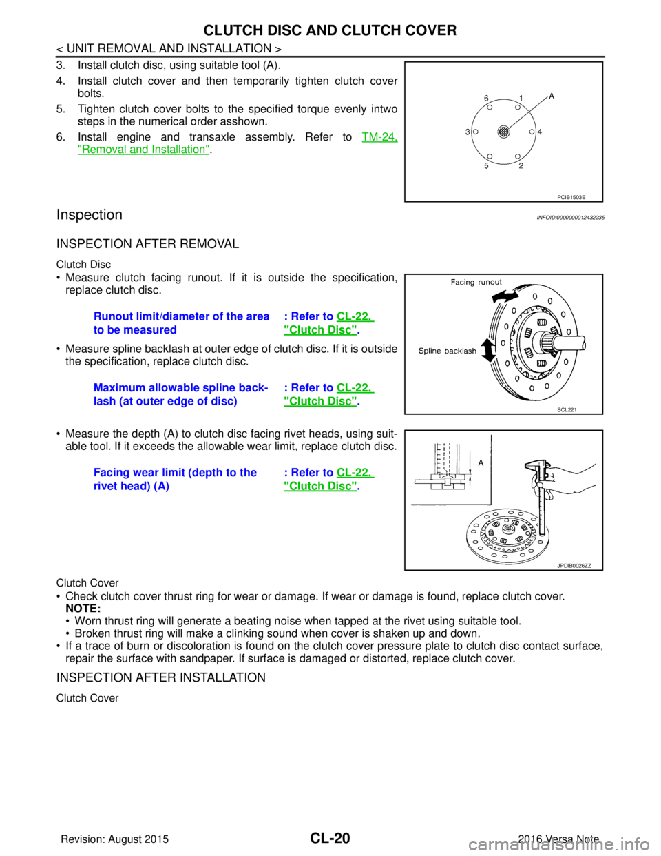
3. Install clutch disc, using suitable tool (A).
4. Install clutch cover and then temporarily tighten clutch coverbolts.
5. Tighten clutch cover bolts to the specified torque evenly intwo steps in the numerical order asshown.
6. Install engine and transaxle assembly. Refer to TM-24,
"Removal and Installation".
InspectionINFOID:0000000012432235
INSPECTION AFTER REMOVAL
Clutch Disc
• Measure clutch facing runout. If it is outside the specification,
replace clutch disc.
• Measure spline backlash at outer edge of clutch disc. If it is outside the specification, replace clutch disc.
• Measure the depth (A) to clutch disc facing rivet heads, using suit- able tool. If it exceeds the allowable wear limit, replace clutch disc.
Clutch Cover
• Check clutch cover thrust ring for wear or damage. If wear or damage is found, replace clutch cover.
NOTE:
• Worn thrust ring will generate a beating noise when tapped at the rivet using suitable tool.
• Broken thrust ring will make a clinking sound when cover is shaken up and down.
• If a trace of burn or discoloration is found on the clutch cover pressure plate to clutch disc contact surface,
repair the surface with sandpaper. If surface is damaged or distorted, replace clutch cover.
INSPECTION AFTER INSTALLATION
Clutch Cover
PCIB1503E
Runout limit/diameter of the area
to be measured : Refer to
CL-22,
"Clutch Disc".
Maximum allowable spline back-
lash (at outer edge of disc) : Refer to
CL-22,
"Clutch Disc".SCL221
Facing wear limit (depth to the
rivet head) (A) : Refer to
CL-22,
"Clutch Disc".
JPDIB0026ZZ
Revision: August 2015 2016 Versa Note
cardiagn.com
Page 647 of 3641
CLUTCH DISC AND CLUTCH COVERCL-21
< UNIT REMOVAL AND INSTALLATION >
CEF
G H
I
J
K L
M A
B
CL
N
O P
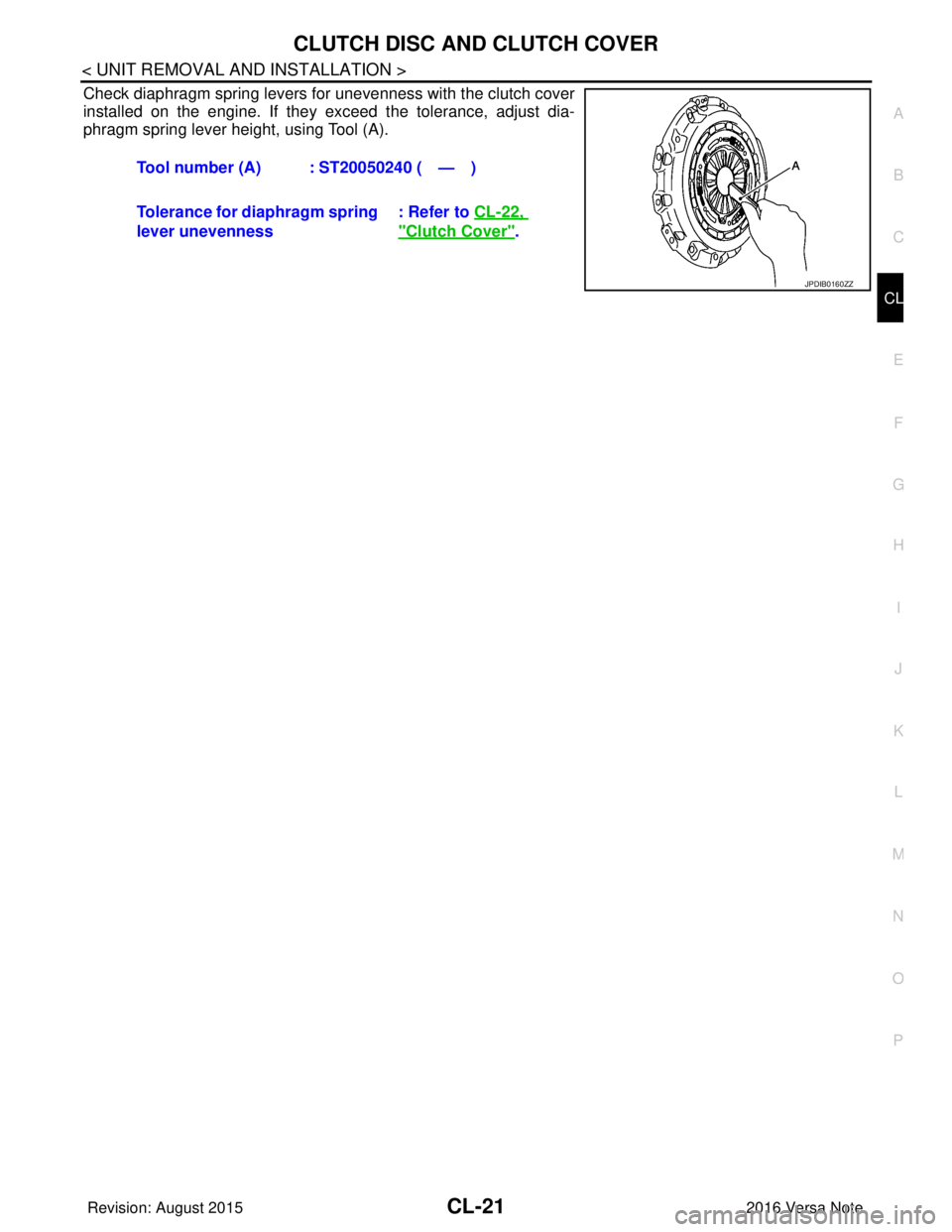
Check diaphragm spring levers for unevenness with the clutch cover
installed on the engine. If they exceed the tolerance, adjust dia-
phragm spring lever height, using Tool (A). Tool number (A) : ST20050240 ( — )
Tolerance for diaphragm spring
lever unevenness : Refer to
CL-22,
"Clutch Cover".
JPDIB0160ZZ
Revision: August 2015 2016 Versa Note
cardiagn.com
Page 648 of 3641
CL-22
< SERVICE DATA AND SPECIFICATIONS (SDS)
SERVICE DATA AND SPECIFICATIONS (SDS)
SERVICE DATA AND SPECIFICATIONS (SDS)
SERVICE DATA AND SPECIFICATIONS (SDS)
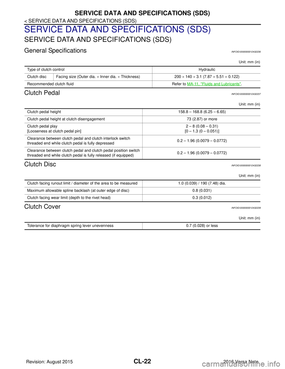
General SpecificationsINFOID:0000000012432236
Unit: mm (in)
Clutch PedalINFOID:0000000012432237
Unit: mm (in)
Clutch DiscINFOID:0000000012432238
Unit: mm (in)
Clutch CoverINFOID:0000000012432239
Unit: mm (in)
Type of clutch controlHydraulic
Clutch disc Facing size (Outer dia. × Inner dia. × Thickness) 200 × 140 × 3.1 (7.87 × 5.51 × 0.122)
Recommended clutch fluid Refer to MA-11, "
Fluids and Lubricants".
Clutch pedal height 158.8 – 168.8 (6.25 – 6.65)
Clutch pedal height at clutch disengagement 73 (2.87) or more
Clutch pedal play
[Looseness at clutch pedal pin] 2 – 8 (0.08 – 0.31)
[0 – 1.3 (0 – 0.051)]
Clearance between clutch pedal and clutch interlock switch
threaded end while clutch pedal is fully depressed 0.2 – 1.96 (0.0079 – 0.0772)
Clearance between clutch pedal and clutch pedal position switch
threaded end while clutch pedal is fully released (if equipped) 0.2 – 1.96 (0.0079 – 0.0772)
Clutch facing runout limit / diameter of the area to be measured
1.0 (0.039) / 190 (7.48) dia.
Maximum allowable spline backlash (at outer edge of disc) 0.8 (0.031)
Clutch facing wear limit (depth to the rivet head) 0.3 (0.012)
Tolerance for diaphragm spring lever unevenness0.7 (0.028) or less
Revision: August 2015 2016 Versa Note
cardiagn.com
Page 649 of 3641

CCS-1
CRUISE CONTROL & DRIVER ASSISTANCE
C
DE
F
G H
I
J
K L
M B
CCS
SECTION CCS
N
P A
CONTENTS
CRUISE CONTROL SYSTEM
ASCD
PRECAUTION ....... ........................................
2
PRECAUTIONS .............................................. .....2
Precaution for Supplemental Restraint System
(SRS) "AIR BAG" and "SEAT BELT PRE-TEN-
SIONER" ............................................................. ......
2
SYSTEM DESCRIPTION ..............................3
AUTOMATIC SPEED CONTROL DEVICE
(ASCD) ...............................................................
3
Information ........................................................... .....3
Revision: August 2015 2016 Versa Note
cardiagn.com
Page 650 of 3641
![NISSAN NOTE 2016 Service Repair Manual CCS-2
< PRECAUTION >[ASCD]
PRECAUTIONS
PRECAUTION
PRECAUTIONS
Precaution for Supplemental Restraint Syst
em (SRS) "AIR BAG" and "SEAT BELT
PRE-TENSIONER"
INFOID:0000000012542559
The Supplemental Rest NISSAN NOTE 2016 Service Repair Manual CCS-2
< PRECAUTION >[ASCD]
PRECAUTIONS
PRECAUTION
PRECAUTIONS
Precaution for Supplemental Restraint Syst
em (SRS) "AIR BAG" and "SEAT BELT
PRE-TENSIONER"
INFOID:0000000012542559
The Supplemental Rest](/img/5/57363/w960_57363-649.png)
CCS-2
< PRECAUTION >[ASCD]
PRECAUTIONS
PRECAUTION
PRECAUTIONS
Precaution for Supplemental Restraint Syst
em (SRS) "AIR BAG" and "SEAT BELT
PRE-TENSIONER"
INFOID:0000000012542559
The Supplemental Restraint System such as “A IR BAG” and “SEAT BELT PRE-TENSIONER”, used along
with a front seat belt, helps to reduce the risk or severity of injury to the driver and front passenger for certain
types of collision. Information necessary to service the system safely is included in the SR and SB section of
this Service Manual.
WARNING:
• To avoid rendering the SRS inopera tive, which could increase the risk of personal injury or death in
the event of a collision which would result in air bag inflation, all maintenance must be performed by
an authorized NISSAN/INFINITI dealer.
• Improper maintenance, including in correct removal and installation of the SRS, can lead to personal
injury caused by unintent ional activation of the system. For re moval of Spiral Cable and Air Bag
Module, see the SR section.
• Do not use electrical test equipmen t on any circuit related to the SRS unless instructed to in this
Service Manual. SRS wiring harn esses can be identified by yellow and/or orange harnesses or har-
ness connectors.
PRECAUTIONS WHEN USING POWER TOOLS (AIR OR ELECTRIC) AND HAMMERS
WARNING:
• When working near the Airbag Diagnosis Sensor Unit or other Airbag System sensors with the Igni-
tion ON or engine running, DO NOT use air or electri c power tools or strike near the sensor(s) with a
hammer. Heavy vibration could activate the sensor( s) and deploy the air bag(s), possibly causing
serious injury.
• When using air or electric power tools or hammers , always switch the Ignition OFF, disconnect the
battery and wait at least three minutes before performing any service.
Revision: August 2015 2016 Versa Note
cardiagn.com