NISSAN PATROL 1998 Y61 / 5.G Electrical System Workshop Manual
PATROL 1998 Y61 / 5.G
NISSAN
NISSAN
https://www.carmanualsonline.info/img/5/616/w960_616-0.png
NISSAN PATROL 1998 Y61 / 5.G Electrical System Workshop Manual
Trending: Oil pressure, harnes, instrument panel, starter, ECU, Combination meter charge, set clock
Page 121 of 326
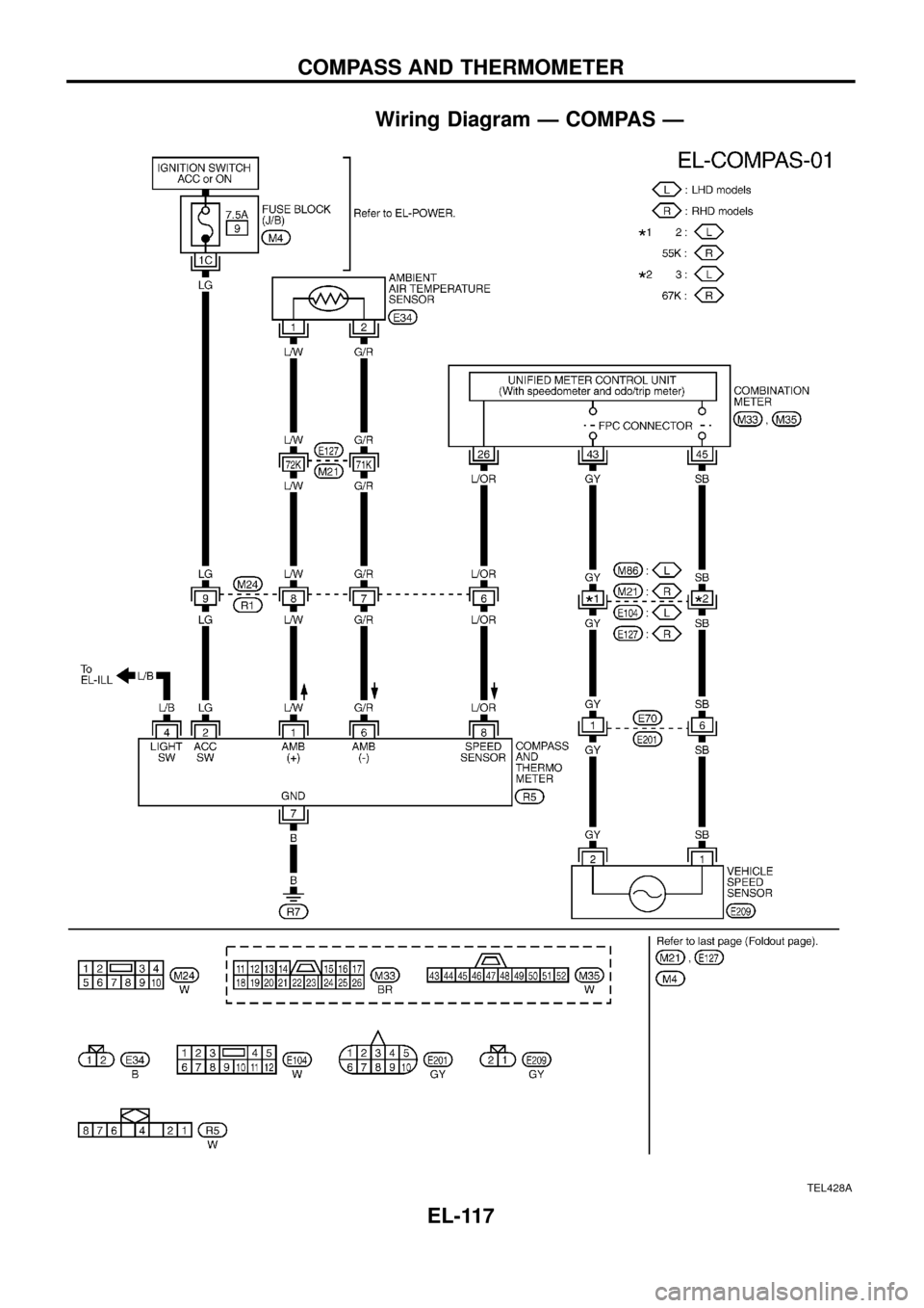
Wiring Diagram Ð COMPAS Ð
TEL428A
COMPASS AND THERMOMETER
EL-117
Page 122 of 326
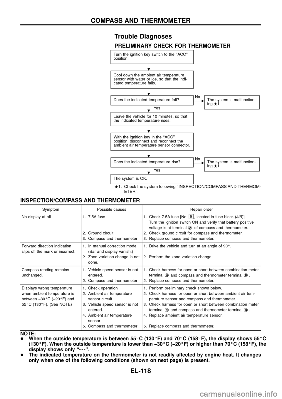
Trouble Diagnoses
PRELIMINARY CHECK FOR THERMOMETER
Turn the ignition key switch to the ``ACC''
position.
Cool down the ambient air temperature
sensor with water or ice, so that the indi-
cated temperature falls.
Does the indicated temperature fall?
Ye s
cNo
The system is malfunction-
ing..1
Leave the vehicle for 10 minutes, so that
the indicated temperature rises.
With the ignition key in the ``ACC''
position, disconnect and reconnect the
ambient air temperature sensor connector.
Does the indicated temperature rise?
Ye s
cNo
The system is malfunction-
ing..1
The system is OK.
.1: Check the system following ``INSPECTION/COMPASS AND THERMOM-
ETER''.
INSPECTION/COMPASS AND THERMOMETER
Symptom Possible causes Repair order
No display at all 1. 7.5A fuse
2. Ground circuit
3. Compass and thermometer1. Check 7.5A fuse [No.
9, located in fuse block (J/B)].
Turn the ignition switch ON and verify that battery positive
voltage is at terminalj
2of compass and thermometer.
2. Check ground circuit for compass and thermometer.
3. Replace compass and thermometer.
Forward direction indication
slips off the mark or incorrect.1. In manual correction mode
(Bar and display vanish.)
2. Zone variation change is not
done.1. Drive the vehicle and turn at an angle of 90É.
2. Perform the zone variation change.
Compass reading remains
unchanged.1. Vehicle speed sensor is not
entered.
2. Compass and thermometer1. Check harness for open or short between combination meter
terminalj
26and compass and thermometer terminalj8.
2. Replace compass and thermometer.
Displays wrong temperature
when ambient temperature is
between þ30ÉC (þ20ÉF) and
55ÉC (130ÉF). (See NOTE)1. Check operation
2. Ambient air temperature
sensor circuit
3. Vehicle speed sensor is not
entered.
4. Ambient air temperature
sensor
5. Compass and thermometer1. Perform preliminary check shown below.
2. Check harness for open or short between ambient air tem-
perature sensor and compass and thermometer.
3. Check harness for open or short between combination meter
terminalj
26and compass and thermometer terminalj8.
4. Replace ambient air temperature sensor.
5. Replace compass and thermometer.
NOTE:
+When the outside temperature is between 55ÉC (130ÉF) and 70ÉC (158ÉF), the display shows 55ÉC
(130ÉF). When the outside temperature is lower than þ30ÉC (þ20ÉF) or higher than 70ÉC (158ÉF), the
display shows only ``- - -''.
+The indicated temperature on the thermometer is not readily affected by engine heat. It changes
only when one of the following conditions (shown on next page) is present.
.
.
.
.
.
.
COMPASS AND THERMOMETER
EL-118
Page 123 of 326
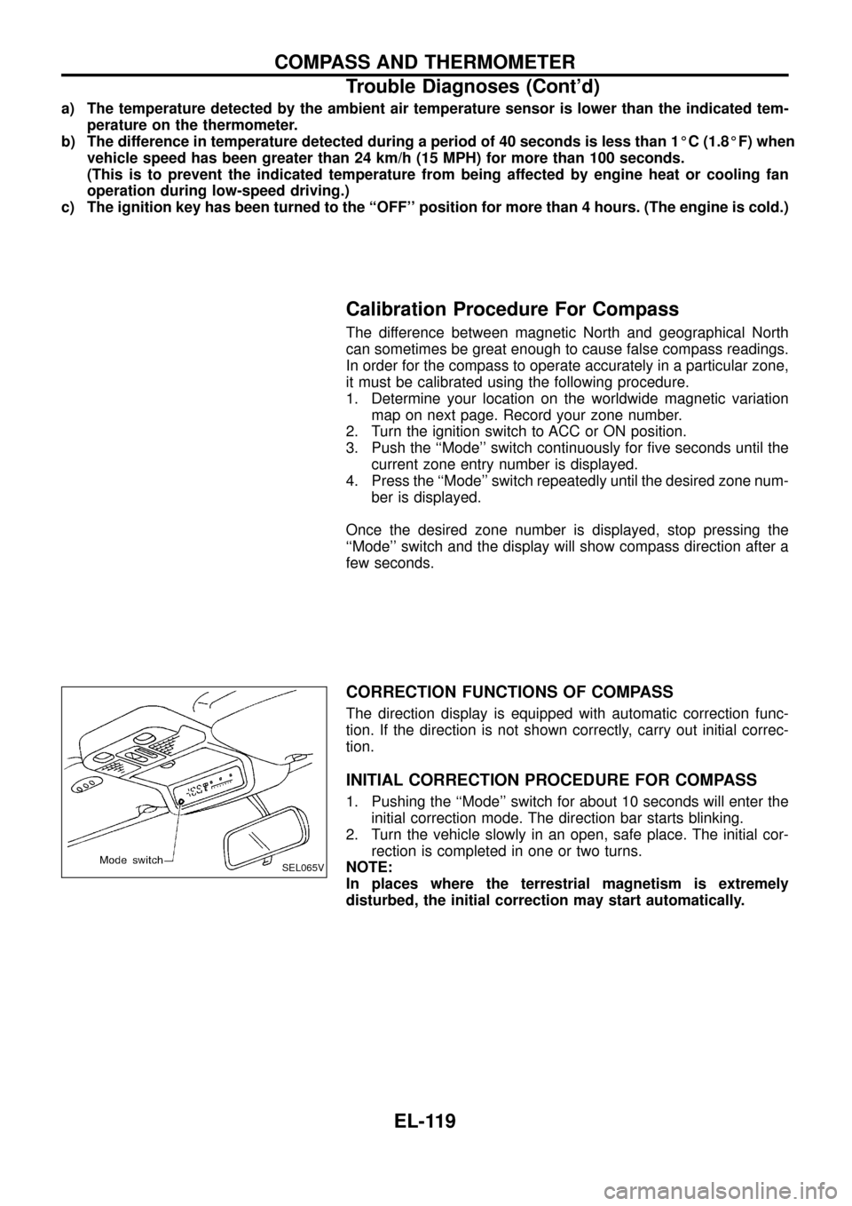
a) The temperature detected by the ambient air temperature sensor is lower than the indicated tem-
perature on the thermometer.
b) The difference in temperature detected during a period of 40 seconds is less than 1ÉC (1.8ÉF) when
vehicle speed has been greater than 24 km/h (15 MPH) for more than 100 seconds.
(This is to prevent the indicated temperature from being affected by engine heat or cooling fan
operation during low-speed driving.)
c) The ignition key has been turned to the ``OFF'' position for more than 4 hours. (The engine is cold.)
Calibration Procedure For Compass
The difference between magnetic North and geographical North
can sometimes be great enough to cause false compass readings.
In order for the compass to operate accurately in a particular zone,
it must be calibrated using the following procedure.
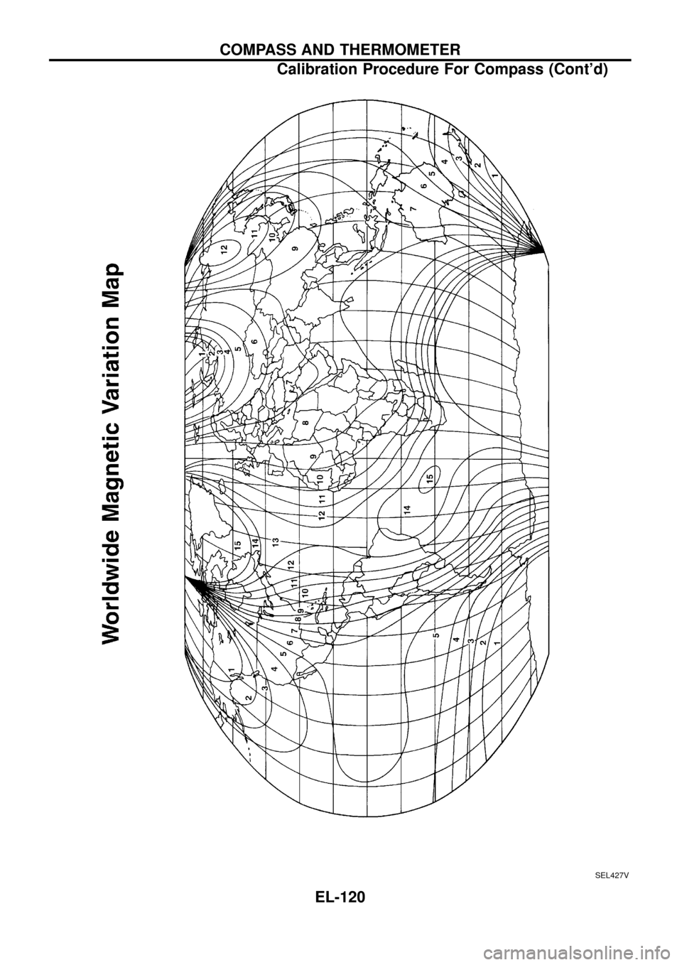
1. Determine your location on the worldwide magnetic variation
map on next page. Record your zone number.
2. Turn the ignition switch to ACC or ON position.
3. Push the ``Mode'' switch continuously for ®ve seconds until the
current zone entry number is displayed.
4. Press the ``Mode'' switch repeatedly until the desired zone num-
ber is displayed.
Once the desired zone number is displayed, stop pressing the
``Mode'' switch and the display will show compass direction after a
few seconds.
CORRECTION FUNCTIONS OF COMPASS
The direction display is equipped with automatic correction func-
tion. If the direction is not shown correctly, carry out initial correc-
tion.
INITIAL CORRECTION PROCEDURE FOR COMPASS
1. Pushing the ``Mode'' switch for about 10 seconds will enter the
initial correction mode. The direction bar starts blinking.
2. Turn the vehicle slowly in an open, safe place. The initial cor-
rection is completed in one or two turns.
NOTE:
In places where the terrestrial magnetism is extremely
disturbed, the initial correction may start automatically.
SEL065V
COMPASS AND THERMOMETER
Trouble Diagnoses (Cont'd)
EL-119
Page 124 of 326
SEL427V
COMPASS AND THERMOMETER
Calibration Procedure For Compass (Cont'd)
EL-120
Page 125 of 326
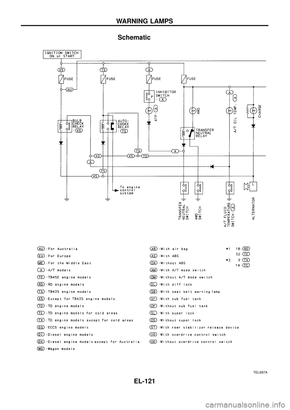
Schematic
TEL697A
WARNING LAMPS
EL-121
Page 126 of 326
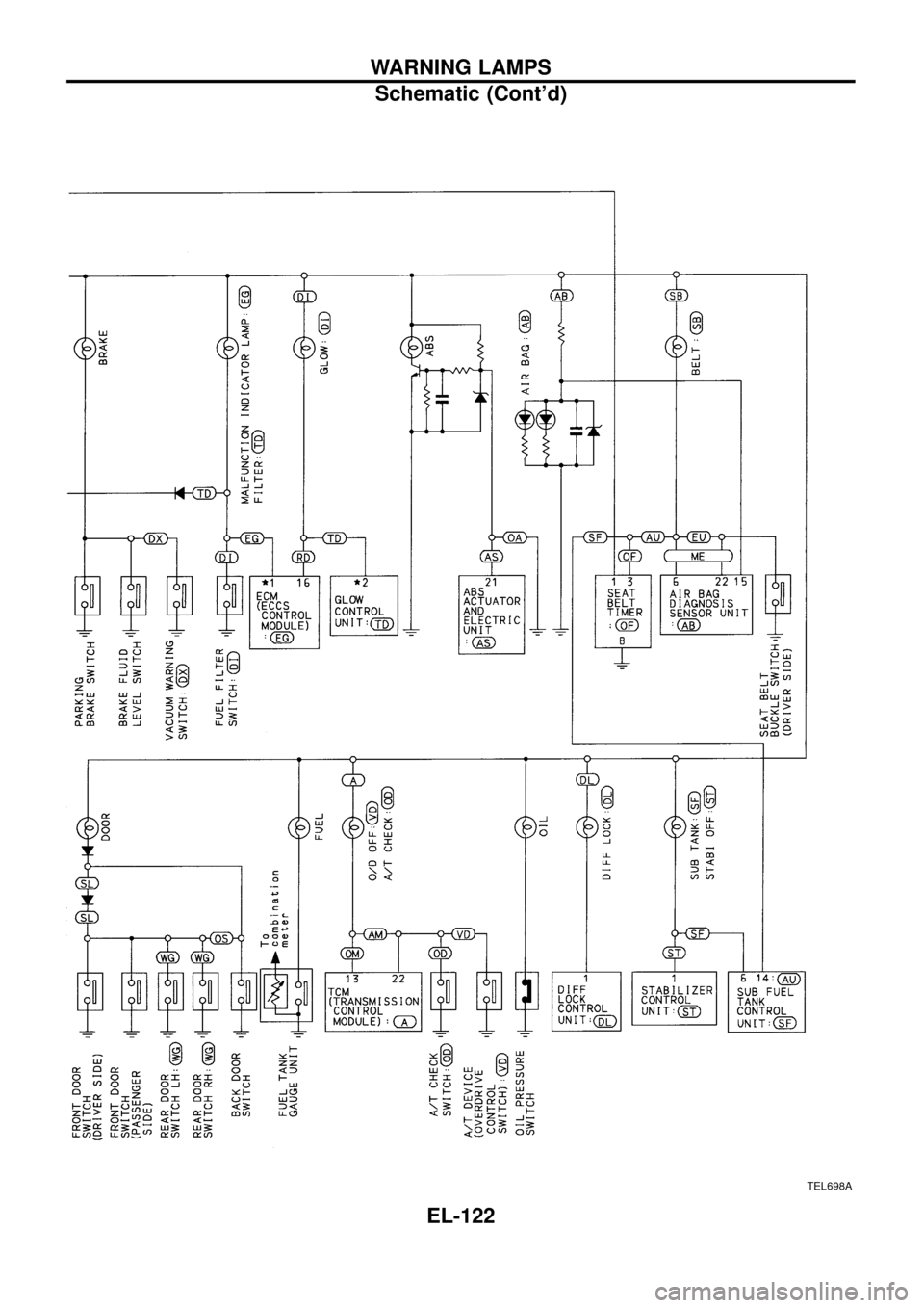
TEL698A
WARNING LAMPS
Schematic (Cont'd)
EL-122
Page 127 of 326
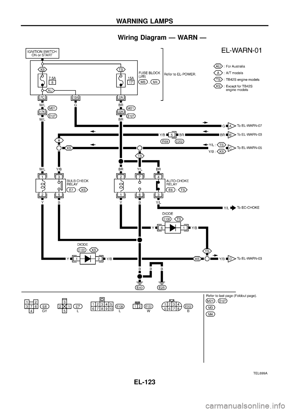
Wiring Diagram Ð WARN Ð
TEL699A
WARNING LAMPS
EL-123
Page 128 of 326
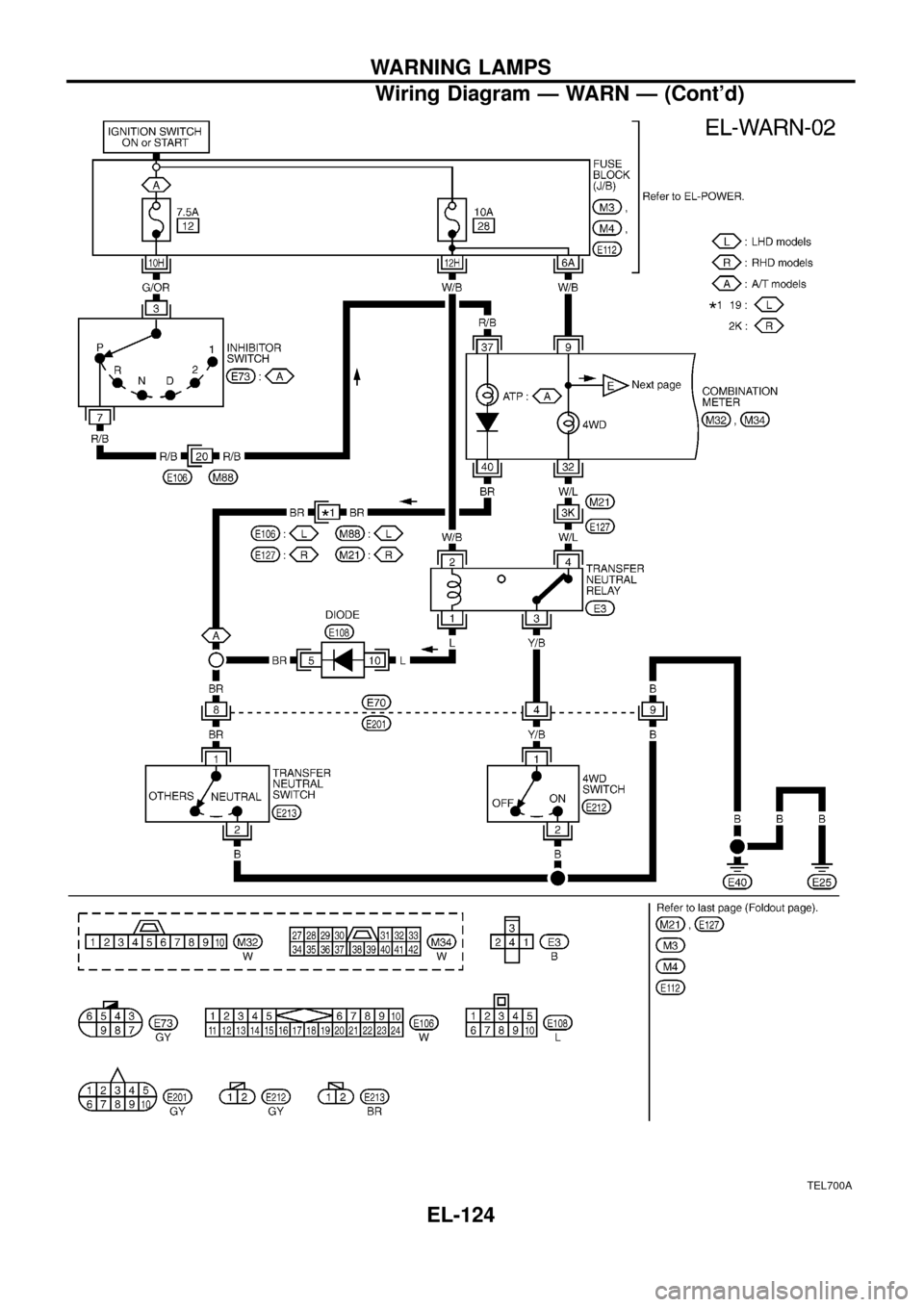
TEL700A
WARNING LAMPS
Wiring Diagram Ð WARN Ð (Cont'd)
EL-124
Page 129 of 326
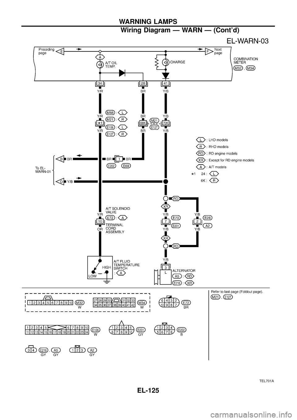
TEL701A
WARNING LAMPS
Wiring Diagram Ð WARN Ð (Cont'd)
EL-125
Page 130 of 326
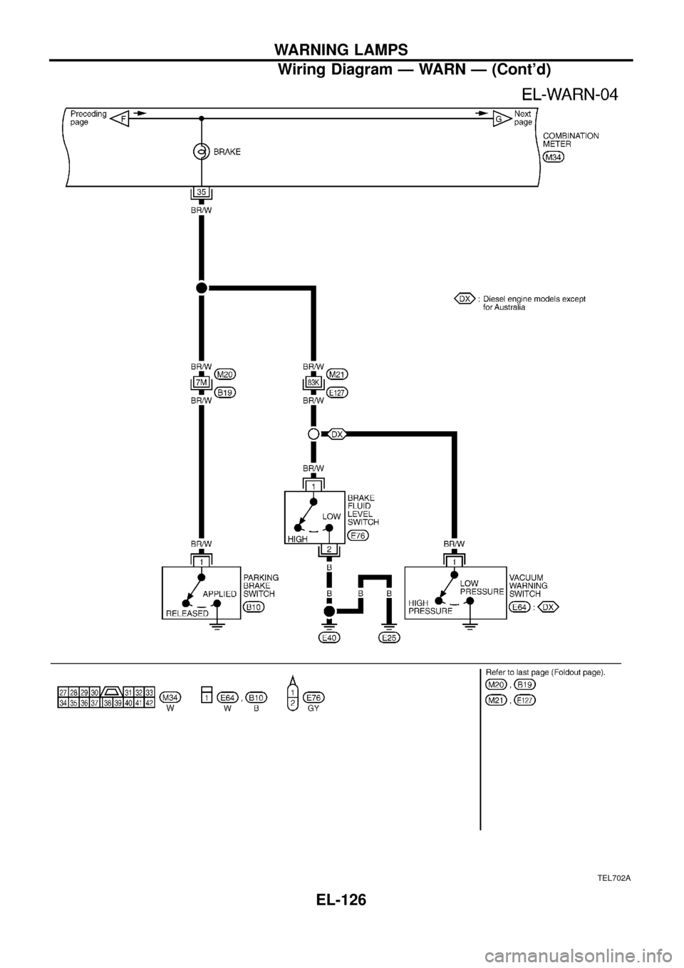
TEL702A
WARNING LAMPS
Wiring Diagram Ð WARN Ð (Cont'd)
EL-126
Trending: Audio, turn signal, Accelerator position sensor, Air flow, clutch, Fuel solenoid, Back
