NISSAN PATROL 1998 Y61 / 5.G Electrical System Workshop Manual
PATROL 1998 Y61 / 5.G
NISSAN
NISSAN
https://www.carmanualsonline.info/img/5/616/w960_616-0.png
NISSAN PATROL 1998 Y61 / 5.G Electrical System Workshop Manual
Trending: Ac switch, brake, Engine room harness, Starter motor, sen, check engine, sub tank control system
Page 161 of 326
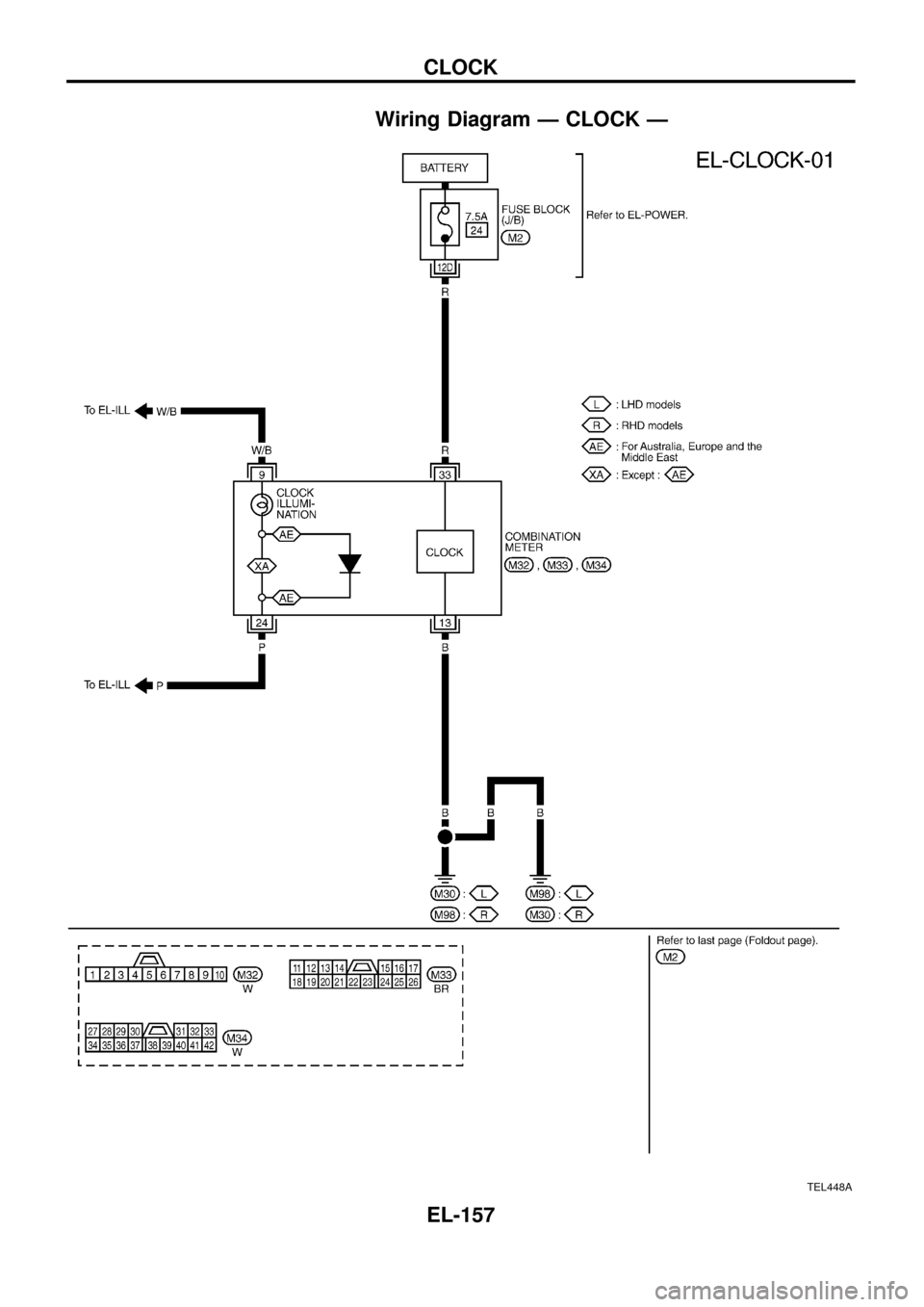
Wiring Diagram Ð CLOCK Ð
TEL448A
CLOCK
EL-157
Page 162 of 326
System Description
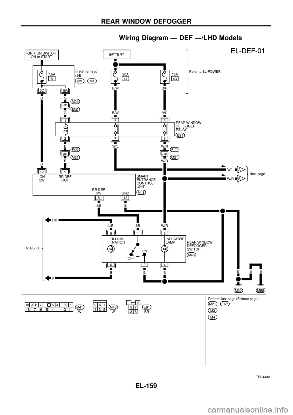
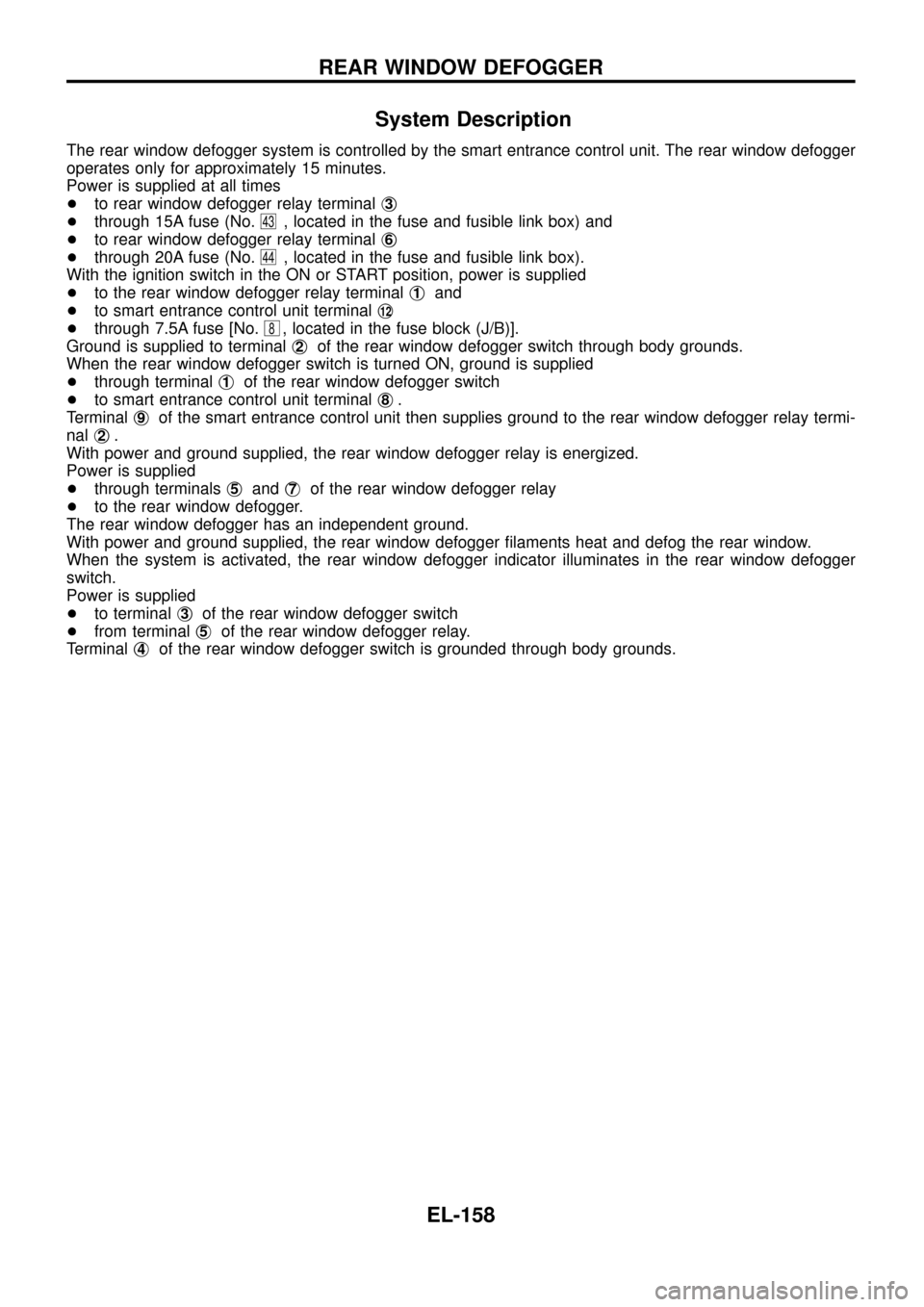
The rear window defogger system is controlled by the smart entrance control unit. The rear window defogger
operates only for approximately 15 minutes.
Power is supplied at all times
+to rear window defogger relay terminalj
3
+through 15A fuse (No.43, located in the fuse and fusible link box) and
+to rear window defogger relay terminalj
6
+through 20A fuse (No.44, located in the fuse and fusible link box).
With the ignition switch in the ON or START position, power is supplied
+to the rear window defogger relay terminalj
1and
+to smart entrance control unit terminalj
12
+through 7.5A fuse [No.8, located in the fuse block (J/B)].
Ground is supplied to terminalj
2of the rear window defogger switch through body grounds.
When the rear window defogger switch is turned ON, ground is supplied
+through terminalj
1of the rear window defogger switch
+to smart entrance control unit terminalj
8.
Terminalj
9of the smart entrance control unit then supplies ground to the rear window defogger relay termi-
nalj
2.
With power and ground supplied, the rear window defogger relay is energized.
Power is supplied
+through terminalsj
5andj7of the rear window defogger relay
+to the rear window defogger.
The rear window defogger has an independent ground.
With power and ground supplied, the rear window defogger ®laments heat and defog the rear window.
When the system is activated, the rear window defogger indicator illuminates in the rear window defogger
switch.
Power is supplied
+to terminalj
3of the rear window defogger switch
+from terminalj
5of the rear window defogger relay.
Terminalj
4of the rear window defogger switch is grounded through body grounds.
REAR WINDOW DEFOGGER
EL-158
Page 163 of 326
Wiring Diagram Ð DEF Ð/LHD Models
TEL449A
REAR WINDOW DEFOGGER
EL-159
Page 164 of 326
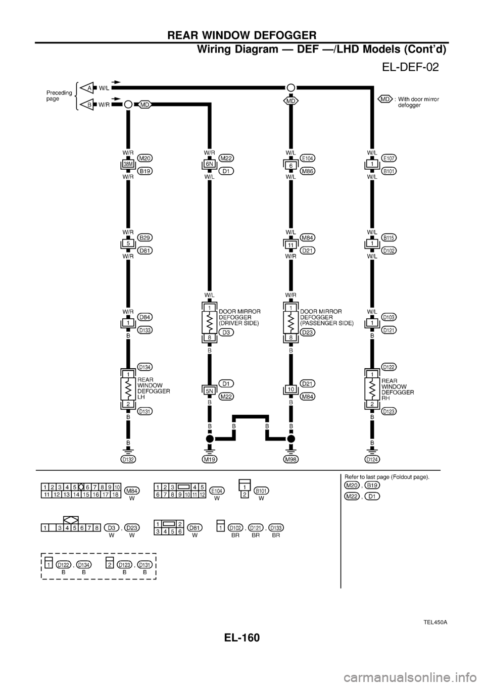
TEL450A
REAR WINDOW DEFOGGER
Wiring Diagram Ð DEF Ð/LHD Models (Cont'd)
EL-160
Page 165 of 326
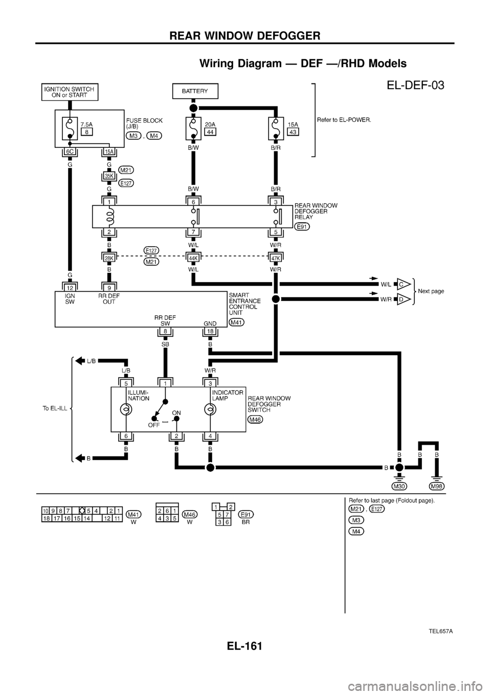
Wiring Diagram Ð DEF Ð/RHD Models
TEL657A
REAR WINDOW DEFOGGER
EL-161
Page 166 of 326
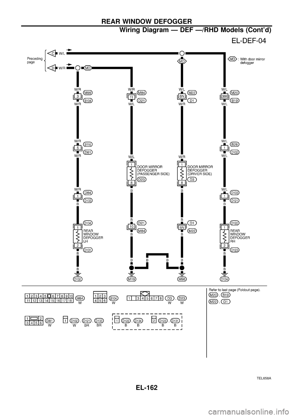
TEL658A
REAR WINDOW DEFOGGER
Wiring Diagram Ð DEF Ð/RHD Models (Cont'd)
EL-162
Page 167 of 326
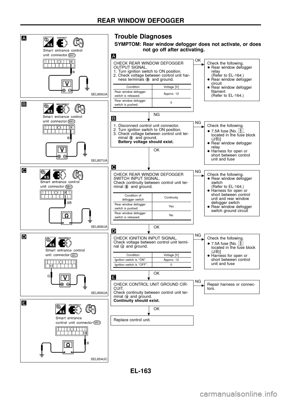
Trouble Diagnoses
SYMPTOM: Rear window defogger does not activate, or does
not go off after activating.
CHECK REAR WINDOW DEFOGGER
OUTPUT SIGNAL.
1. Turn ignition switch to ON position.
2. Check voltage between control unit har-
ness terminalsj
9and ground.
NG
cOK
Check the following.
+Rear window defogger
relay
(Refer to EL-164.)
+Rear window defogger
circuit
+Rear window defogger
®lament
(Refer to EL-164.)
1. Disconnect control unit connector.
2. Turn ignition switch to ON position.
3. Check voltage between control unit ter-
minalj
9and ground.
Battery voltage should exist.
OK
cNG
Check the following.
+7.5A fuse [No.
8,
located in the fuse block
(J/B)]
+Rear window defogger
relay
+Harness for open or
short between control
unit and fuse
CHECK REAR WINDOW DEFOGGER
SWITCH INPUT SIGNAL.
Check continuity between control unit ter-
minalj
8and ground.
OK
cNG
Check the following.
+Rear window defogger
switch
(Refer to EL-164.)
+Harness for open or
short between control
unit and rear window
defogger switch
+Rear window defogger
switch ground circuit
CHECK IGNITION INPUT SIGNAL.
Check voltage between control unit termi-
nalj
12and ground.
OK
cNG
Check the following.
+7.5A fuse [No.
8located in the fuse block
(J/B)]
+Harness for open or
short between control
unit and fuse
CHECK CONTROL UNIT GROUND CIR-
CUIT.
Check continuity between control unit ter-
minalj
18and ground.
Continuity should exist.
OK
cNG
Repair harness or connec-
tors.
Replace control unit.
Condition Voltage [V]
Rear window defogger
switch is released.Approx. 12
Rear window defogger
switch is pushed.0
Condition of
defogger switchContinuity
Rear window defogger
switch is pushed.Ye s
Rear window defogger
switch is released.No
Condition Voltage [V]
Ignition switch is ``ON''. Approx. 12
Ignition switch is ``OFF''. 0
SEL856UA
SEL857UA
SEL858UA
SEL859UA
SEL854UC
.
.
.
.
.
REAR WINDOW DEFOGGER
EL-163
Page 168 of 326
Electrical Components Inspection
REAR WINDOW DEFOGGER RELAY
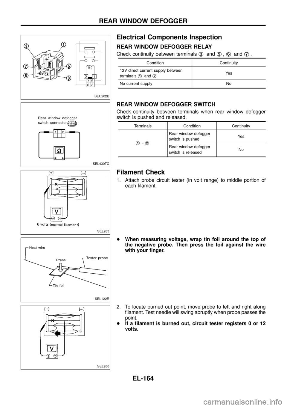
Check continuity between terminalsj3andj5,j6andj7.
Condition Continuity
12V direct current supply between
terminalsj
1andj2Ye s
No current supply No
REAR WINDOW DEFOGGER SWITCH
Check continuity between terminals when rear window defogger
switch is pushed and released.
Terminals Condition Continuity
j
1-j2
Rear window defogger
switch is pushedYe s
Rear window defogger
switch is releasedNo
Filament Check
1. Attach probe circuit tester (in volt range) to middle portion of
each ®lament.
+When measuring voltage, wrap tin foil around the top of
the negative probe. Then press the foil against the wire
with your ®nger.
2. To locate burned out point, move probe to left and right along
®lament. Test needle will swing abruptly when probe passes the
point.
+If a ®lament is burned out, circuit tester registers 0 or 12
volts.
SEC202B
SEL430TC
SEL263
SEL122R
SEL266
REAR WINDOW DEFOGGER
EL-164
Page 169 of 326
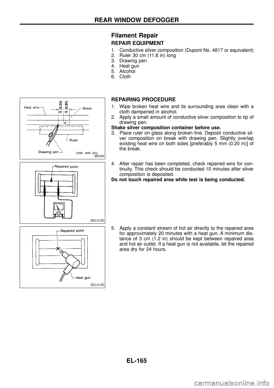
Filament Repair
REPAIR EQUIPMENT
1. Conductive silver composition (Dupont No. 4817 or equivalent)
2. Ruler 30 cm (11.8 in) long
3. Drawing pen
4. Heat gun
5. Alcohol
6. Cloth
REPAIRING PROCEDURE
1. Wipe broken heat wire and its surrounding area clean with a
cloth dampened in alcohol.
2. Apply a small amount of conductive silver composition to tip of
drawing pen.
Shake silver composition container before use.
3. Place ruler on glass along broken line. Deposit conductive sil-
ver composition on break with drawing pen. Slightly overlap
existing heat wire on both sides [preferably 5 mm (0.20 in)] of
the break.
4. After repair has been completed, check repaired wire for con-
tinuity. This check should be conducted 10 minutes after silver
composition is deposited.
Do not touch repaired area while test is being conducted.
5. Apply a constant stream of hot air directly to the repaired area
for approximately 20 minutes with a heat gun. A minimum dis-
tance of 3 cm (1.2 in) should be kept between repaired area
and hot air outlet. If a heat gun is not available, let the repaired
area dry for 24 hours.
BE540
SEL012D
SEL013D
REAR WINDOW DEFOGGER
EL-165
Page 170 of 326
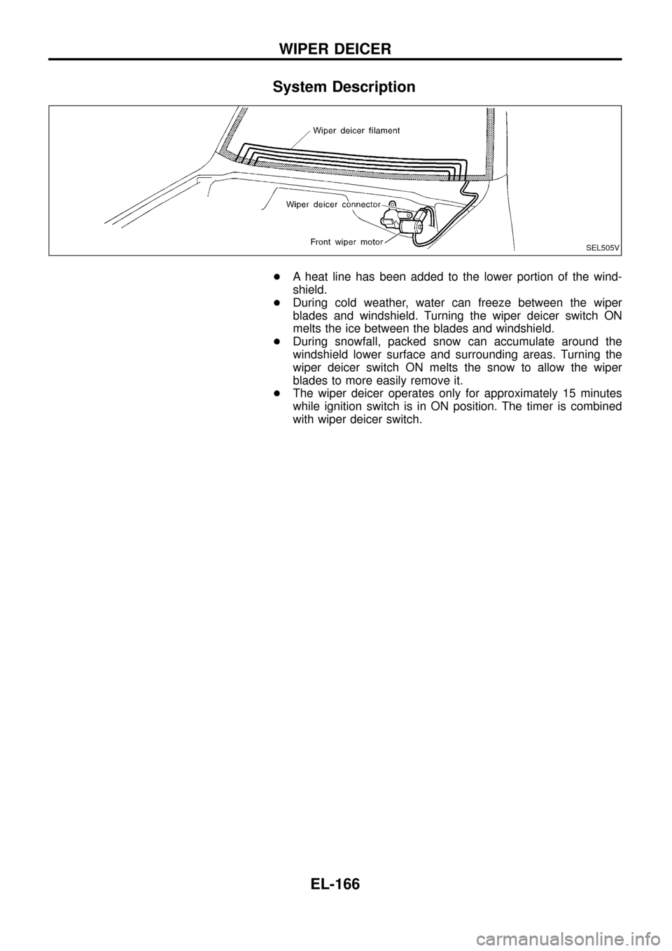
System Description
+A heat line has been added to the lower portion of the wind-
shield.
+During cold weather, water can freeze between the wiper
blades and windshield. Turning the wiper deicer switch ON
melts the ice between the blades and windshield.
+During snowfall, packed snow can accumulate around the
windshield lower surface and surrounding areas. Turning the
wiper deicer switch ON melts the snow to allow the wiper
blades to more easily remove it.
+The wiper deicer operates only for approximately 15 minutes
while ignition switch is in ON position. The timer is combined
with wiper deicer switch.
SEL505V
WIPER DEICER
EL-166
Trending: Park light wiring, section EC, service reset, battery location, Meter control unit, Wiring fuel, tow
