at control NISSAN PATROL 1998 Y61 / 5.G Electrical System Owner's Manual
[x] Cancel search | Manufacturer: NISSAN, Model Year: 1998, Model line: PATROL, Model: NISSAN PATROL 1998 Y61 / 5.GPages: 326, PDF Size: 11.36 MB
Page 162 of 326
System Description
The rear window defogger system is controlled by the smart entrance control unit. The rear window defogger
operates only for approximately 15 minutes.
Power is supplied at all times
+to rear window defogger relay terminalj
3
+through 15A fuse (No.43, located in the fuse and fusible link box) and
+to rear window defogger relay terminalj
6
+through 20A fuse (No.44, located in the fuse and fusible link box).
With the ignition switch in the ON or START position, power is supplied
+to the rear window defogger relay terminalj
1and
+to smart entrance control unit terminalj
12
+through 7.5A fuse [No.8, located in the fuse block (J/B)].
Ground is supplied to terminalj
2of the rear window defogger switch through body grounds.
When the rear window defogger switch is turned ON, ground is supplied
+through terminalj
1of the rear window defogger switch
+to smart entrance control unit terminalj
8.
Terminalj
9of the smart entrance control unit then supplies ground to the rear window defogger relay termi-
nalj
2.
With power and ground supplied, the rear window defogger relay is energized.
Power is supplied
+through terminalsj
5andj7of the rear window defogger relay
+to the rear window defogger.
The rear window defogger has an independent ground.
With power and ground supplied, the rear window defogger ®laments heat and defog the rear window.
When the system is activated, the rear window defogger indicator illuminates in the rear window defogger
switch.
Power is supplied
+to terminalj
3of the rear window defogger switch
+from terminalj
5of the rear window defogger relay.
Terminalj
4of the rear window defogger switch is grounded through body grounds.
REAR WINDOW DEFOGGER
EL-158
Page 167 of 326
Trouble Diagnoses
SYMPTOM: Rear window defogger does not activate, or does
not go off after activating.
CHECK REAR WINDOW DEFOGGER
OUTPUT SIGNAL.
1. Turn ignition switch to ON position.
2. Check voltage between control unit har-
ness terminalsj
9and ground.
NG
cOK
Check the following.
+Rear window defogger
relay
(Refer to EL-164.)
+Rear window defogger
circuit
+Rear window defogger
®lament
(Refer to EL-164.)
1. Disconnect control unit connector.
2. Turn ignition switch to ON position.
3. Check voltage between control unit ter-
minalj
9and ground.
Battery voltage should exist.
OK
cNG
Check the following.
+7.5A fuse [No.
8,
located in the fuse block
(J/B)]
+Rear window defogger
relay
+Harness for open or
short between control
unit and fuse
CHECK REAR WINDOW DEFOGGER
SWITCH INPUT SIGNAL.
Check continuity between control unit ter-
minalj
8and ground.
OK
cNG
Check the following.
+Rear window defogger
switch
(Refer to EL-164.)
+Harness for open or
short between control
unit and rear window
defogger switch
+Rear window defogger
switch ground circuit
CHECK IGNITION INPUT SIGNAL.
Check voltage between control unit termi-
nalj
12and ground.
OK
cNG
Check the following.
+7.5A fuse [No.
8located in the fuse block
(J/B)]
+Harness for open or
short between control
unit and fuse
CHECK CONTROL UNIT GROUND CIR-
CUIT.
Check continuity between control unit ter-
minalj
18and ground.
Continuity should exist.
OK
cNG
Repair harness or connec-
tors.
Replace control unit.
Condition Voltage [V]
Rear window defogger
switch is released.Approx. 12
Rear window defogger
switch is pushed.0
Condition of
defogger switchContinuity
Rear window defogger
switch is pushed.Ye s
Rear window defogger
switch is released.No
Condition Voltage [V]
Ignition switch is ``ON''. Approx. 12
Ignition switch is ``OFF''. 0
SEL856UA
SEL857UA
SEL858UA
SEL859UA
SEL854UC
.
.
.
.
.
REAR WINDOW DEFOGGER
EL-163
Page 176 of 326
Trouble Diagnoses
RADIO
Symptom Possible causes Repair order
Radio inoperative (no digital
display and no sound from
speakers).
See NOTE.1. 10A fuse
2. Poor radio case ground
3. Radio1. Check 10A fuse [No.
10, located in fuse block (J/B)].
Turn ignition switch ON and verify battery positive volt-
age is present at terminalj
10of radio.
2. Check radio case ground.
3. Remove radio for repair.
Radio controls are operational,
but no sound is heard from
any speaker.1. Radio output
2. Radio1. Check radio output voltages.
2. Remove radio for repair.
Radio presets are lost when
ignition switch is turned OFF.1. 10A fuse
2. Radio1. Check 10A fuse (No.
56, located in fuse and fusible link
box) and verify battery positive voltage is present at terminal
j
6of radio.
2. Remove radio for repair.
Individual speaker is noisy or
inoperative.1. Speaker
2. Radio output
3. Speaker circuit
4. Radio1. Check speaker.
2. Check radio output voltages.
3. Check wires for open or short between radio and speaker.
4. Remove radio for repair.
Radio stations are weak or
noisy.1. Antenna
2. Poor radio ground
3. Radio1. Check antenna.
2. Check radio ground.
3. Remove radio for repair.
FM stations are weak or noisy
but AM stations are OK. (with
window antenna)1. Window antenna
2. Radio1. Check window antenna.
2. Remove radio for repair.
Radio generates noise in AM
and FM modes with engine
running.1. Poor radio ground
2. Loose or missing ground bonding straps
3. Ignition condenser or rear window defogger
noise suppressor condenser
4. Alternator
5. Ignition coil or secondary wiring
6. Radio1. Check radio ground.
2. Check ground bonding straps.
3. Replace ignition condenser or rear window defogger noise
suppressor condenser.
4. Check alternator.
5. Check ignition coil and secondary wiring.
6. Remove radio for repair.
Radio generates noise in AM
and FM modes with accesso-
ries on (switch pops and motor
noise).1. Poor radio ground
2. Antenna
3. Accessory ground
4. Faulty accessory1. Check radio ground.
2. Check antenna.
3. Check accessory ground.
4. Replace accessory.
NOTE:
If the radio has anti-theft function, check the anti-theft function of the radio before circuit inspection.
(Radios which have anti-theft function are equipped with a code indicator. For details, refer to EL-173.)
Speaker inspection
1. Disconnect speaker harness connector.
2. Measure the resistance between speaker terminalsj
1andj2.
+The resistance should be2-4W.
3. Using jumper wires, momentarily connect a 9V battery between speaker terminalsj
1andj2.
+A momentary hum or pop should be heard.
Antenna inspection
Using a jumper wire, clip an auxiliary ground between antenna and body.
+If reception improves, check antenna ground (at body surface).
+If reception does not improve, check main feeder cable for short circuit or open circuit.
Radio inspection
All voltage inspections are made with:
+Ignition switch ON or ACC
+Radio ON
+Radio connected (If removed for inspection, supply a ground to the case using a jumper wire.)
AUDIO
EL-172
Page 177 of 326
CATS (Code) System/RHD
NOTE:
+This system is used for code indicator-equipped radios on all models except the Europe LHD
model.
+The Europe LHD model has a NATS-linked anti-theft function that renders the code system inop-
erable.
DESCRIPTION
By using a personal 4-digit code known only to the vehicle owner, the possibility of the audio unit being sto-
len is effectively reduced, because without the code the unit can not be activated. When in normal use, the
unit is unlocked and accessible in the usual way.
If however, someone attempts to remove the unit or the battery cable is disconnected, the anti-theft system
activates and the unit ``locks''. The only way it can be unlocked is by entering a personal code number known
only by the owner.
UNLOCKING THE UNIT (How to enter a personal code number)
+If the battery supply to the vehicle is interrupted by accident for some reason, the unit will lock.
To unlock the unit, proceed as follows:
1. Press the power/volume control knob to turn the unit on.
2. ``CODE IN'' is displayed.
3. Input your personal code by pressing the preset buttons (1 to 4).
4. Press the
button.
5. If the entered code number is correct, the radio turns on.
When the code is incorrect
1. If the entered code is incorrect, the unit becomes inoperable for 10 seconds for the ®rst three attempts,
then the code input mode is automatically set (``CODE IN'' is displayed).
2. If the code is incorrect the fourth time, the unit becomes inoperable for 60 minutes and ``
'' is displayed.
After 60 minutes, the code input mode is automatically set (``CODE IN'' is displayed).
NOTE:
If the above is repeated 17 times, the unit will lock and ``LOCKED'' is displayed.
3. After ``LOCKED'' is displayed, radio can be returned to the code input mode only within three attempts as
follows. (Only three attempts are allowed to unlock the unit.)
a. Press the power/volume control knob while pushing both the MOD and TA switches.
b. The unit then returns to the code input mode.
CAUTION:
If the third attempt is unsuccessful, the unit will lock permanently.
AUDIO
EL-173
Page 178 of 326
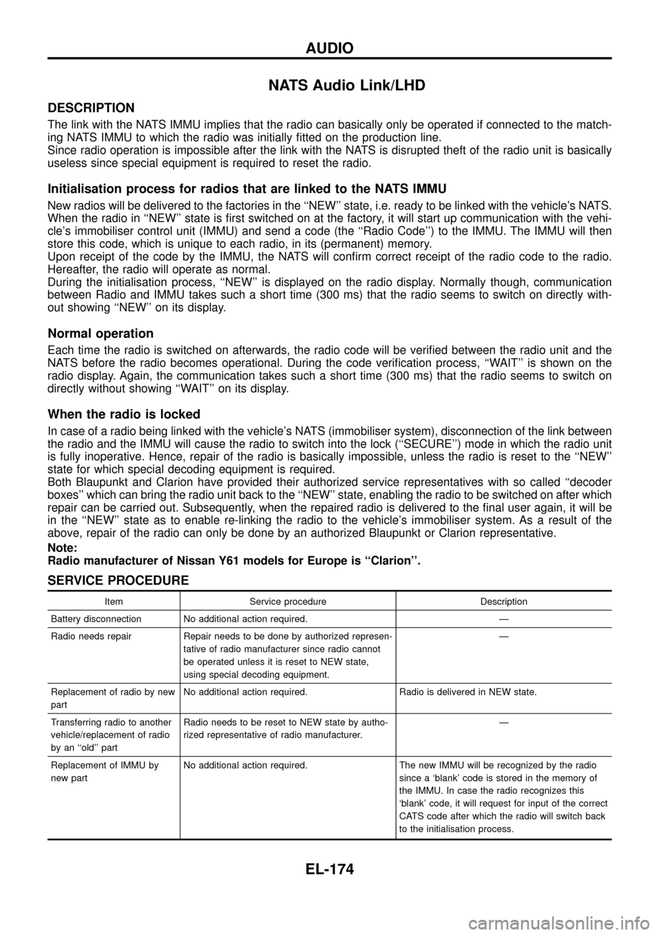
NATS Audio Link/LHD
DESCRIPTION
The link with the NATS IMMU implies that the radio can basically only be operated if connected to the match-
ing NATS IMMU to which the radio was initially ®tted on the production line.
Since radio operation is impossible after the link with the NATS is disrupted theft of the radio unit is basically
useless since special equipment is required to reset the radio.
Initialisation process for radios that are linked to the NATS IMMU
New radios will be delivered to the factories in the ``NEW'' state, i.e. ready to be linked with the vehicle's NATS.
When the radio in ``NEW'' state is ®rst switched on at the factory, it will start up communication with the vehi-
cle's immobiliser control unit (IMMU) and send a code (the ``Radio Code'') to the IMMU. The IMMU will then
store this code, which is unique to each radio, in its (permanent) memory.
Upon receipt of the code by the IMMU, the NATS will con®rm correct receipt of the radio code to the radio.
Hereafter, the radio will operate as normal.
During the initialisation process, ``NEW'' is displayed on the radio display. Normally though, communication
between Radio and IMMU takes such a short time (300 ms) that the radio seems to switch on directly with-
out showing ``NEW'' on its display.
Normal operation
Each time the radio is switched on afterwards, the radio code will be veri®ed between the radio unit and the
NATS before the radio becomes operational. During the code veri®cation process, ``WAIT'' is shown on the
radio display. Again, the communication takes such a short time (300 ms) that the radio seems to switch on
directly without showing ``WAIT'' on its display.
When the radio is locked
In case of a radio being linked with the vehicle's NATS (immobiliser system), disconnection of the link between
the radio and the IMMU will cause the radio to switch into the lock (``SECURE'') mode in which the radio unit
is fully inoperative. Hence, repair of the radio is basically impossible, unless the radio is reset to the ``NEW''
state for which special decoding equipment is required.
Both Blaupunkt and Clarion have provided their authorized service representatives with so called ``decoder
boxes'' which can bring the radio unit back to the ``NEW'' state, enabling the radio to be switched on after which
repair can be carried out. Subsequently, when the repaired radio is delivered to the ®nal user again, it will be
in the ``NEW'' state as to enable re-linking the radio to the vehicle's immobiliser system. As a result of the
above, repair of the radio can only be done by an authorized Blaupunkt or Clarion representative.
Note:
Radio manufacturer of Nissan Y61 models for Europe is ``Clarion''.
SERVICE PROCEDURE
Item Service procedure Description
Battery disconnection No additional action required. Ð
Radio needs repair Repair needs to be done by authorized represen-
tative of radio manufacturer since radio cannot
be operated unless it is reset to NEW state,
using special decoding equipment.Ð
Replacement of radio by new
partNo additional action required. Radio is delivered in NEW state.
Transferring radio to another
vehicle/replacement of radio
by an ``old'' partRadio needs to be reset to NEW state by autho-
rized representative of radio manufacturer.Ð
Replacement of IMMU by
new partNo additional action required. The new IMMU will be recognized by the radio
since a `blank' code is stored in the memory of
the IMMU. In case the radio recognizes this
`blank' code, it will request for input of the correct
CATS code after which the radio will switch back
to the initialisation process.
AUDIO
EL-174
Page 208 of 326
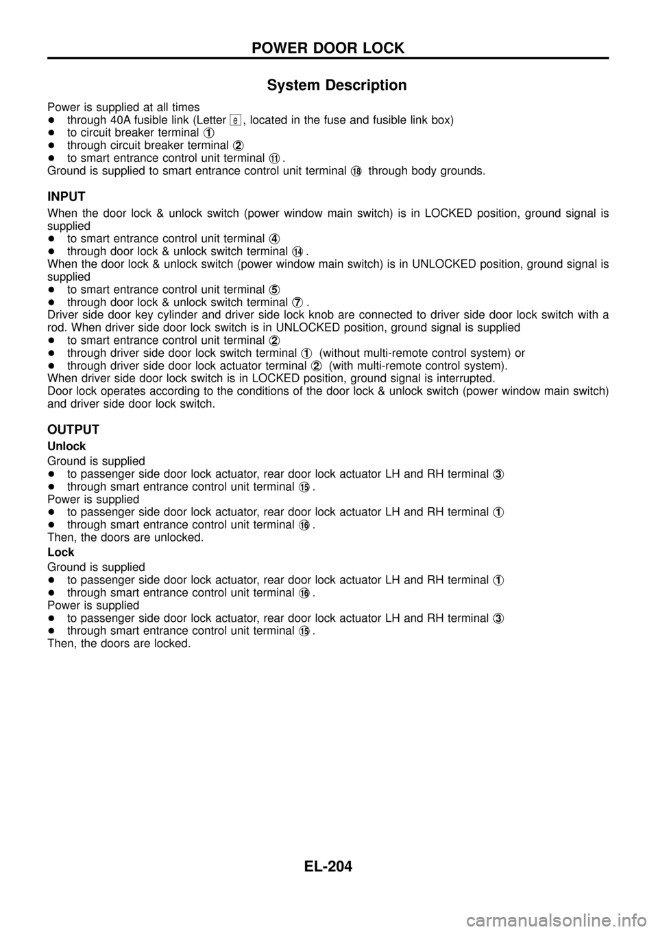
System Description
Power is supplied at all times
+through 40A fusible link (Letter
e, located in the fuse and fusible link box)
+to circuit breaker terminalj
1
+through circuit breaker terminalj2
+to smart entrance control unit terminalj11.
Ground is supplied to smart entrance control unit terminalj
18through body grounds.
INPUT
When the door lock & unlock switch (power window main switch) is in LOCKED position, ground signal is
supplied
+to smart entrance control unit terminalj
4
+through door lock & unlock switch terminalj14.
When the door lock & unlock switch (power window main switch) is in UNLOCKED position, ground signal is
supplied
+to smart entrance control unit terminalj
5
+through door lock & unlock switch terminalj7.
Driver side door key cylinder and driver side lock knob are connected to driver side door lock switch with a
rod. When driver side door lock switch is in UNLOCKED position, ground signal is supplied
+to smart entrance control unit terminalj
2
+through driver side door lock switch terminalj1(without multi-remote control system) or
+through driver side door lock actuator terminalj
2(with multi-remote control system).
When driver side door lock switch is in LOCKED position, ground signal is interrupted.
Door lock operates according to the conditions of the door lock & unlock switch (power window main switch)
and driver side door lock switch.
OUTPUT
Unlock
Ground is supplied
+to passenger side door lock actuator, rear door lock actuator LH and RH terminalj
3
+through smart entrance control unit terminalj15.
Power is supplied
+to passenger side door lock actuator, rear door lock actuator LH and RH terminalj
1
+through smart entrance control unit terminalj16.
Then, the doors are unlocked.
Lock
Ground is supplied
+to passenger side door lock actuator, rear door lock actuator LH and RH terminalj
1
+through smart entrance control unit terminalj16.
Power is supplied
+to passenger side door lock actuator, rear door lock actuator LH and RH terminalj
3
+through smart entrance control unit terminalj15.
Then, the doors are locked.
POWER DOOR LOCK
EL-204
Page 211 of 326
Trouble Diagnosis
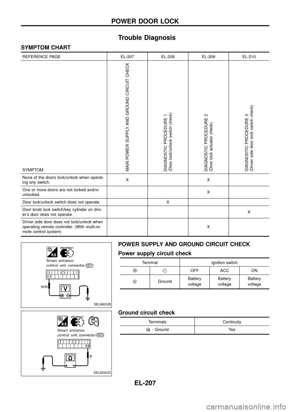
SYMPTOM CHART
REFERENCE PAGE EL-207 EL-208 EL-209 EL-210
SYMPTOM
MAIN POWER SUPPLY AND GROUND CIRCUIT CHECK
DIAGNOSTIC PROCEDURE 1
(Door lock/unlock switch check)
DIAGNOSTIC PROCEDURE 2
(Door lock actuator check)
DIAGNOSTIC PROCEDURE 3
(Driver side door lock switch check)
None of the doors lock/unlock when operat-
ing any switch.XX
One or more doors are not locked and/or
unlocked.X
Door lock/unlock switch does not operate. X
Door knob lock switch/key cylinder on driv-
er's door does not operate.X
Driver side door does not lock/unlock when
operating remote controller. (With multi-re-
mote control system)X
POWER SUPPLY AND GROUND CIRCUIT CHECK
Power supply circuit check
Terminal Ignition switch
Å@OFF ACC ON
j
11GroundBattery
voltageBattery
voltageBattery
voltage
Ground circuit check
Terminals Continuity
j
18- Ground Yes
SEL860UB
SEL854UD
POWER DOOR LOCK
EL-207
Page 212 of 326
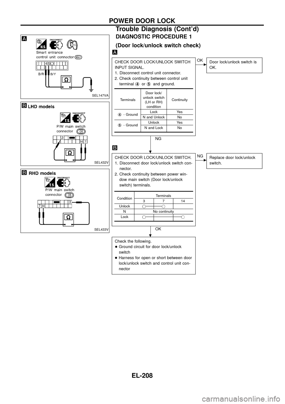
DIAGNOSTIC PROCEDURE 1
(Door lock/unlock switch check)
CHECK DOOR LOCK/UNLOCK SWITCH
INPUT SIGNAL.
1. Disconnect control unit connector.
2. Check continuity between control unit
terminalj
4orj5and ground.
NG
cOK
Door lock/unlock switch is
OK.
CHECK DOOR LOCK/UNLOCK SWITCH.
1. Disconnect door lock/unlock switch con-
nector.
2. Check continuity between power win-
dow main switch (Door lock/unlock
switch) terminals.
OK
cNG
Replace door lock/unlock
switch.
Check the following.
+Ground circuit for door lock/unlock
switch
+Harness for open or short between door
lock/unlock switch and control unit con-
nector
TerminalsDoor lock/
unlock switch
(LH or RH)
conditionContinuity
j
4- GroundLock Yes
N and Unlock No
j
5- GroundUnlock Yes
N and Lock No
ConditionTerminals3714
Unlockjj
N No continuity
Lockjj
SEL147VA
SEL432V
SEL433V
.
.
POWER DOOR LOCK
Trouble Diagnosis (Cont'd)
EL-208
Page 213 of 326
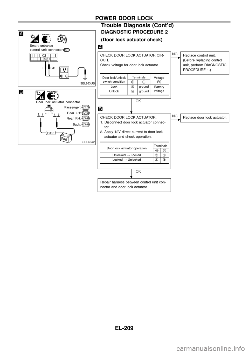
DIAGNOSTIC PROCEDURE 2
(Door lock actuator check)
CHECK DOOR LOCK ACTUATOR CIR-
CUIT.
Check voltage for door lock actuator.
OK
cNG
Replace control unit.
(Before replacing control
unit, perform DIAGNOSTIC
PROCEDURE 1.)
CHECK DOOR LOCK ACTUATOR.
1. Disconnect door lock actuator connec-
tor.
2. Apply 12V direct current to door lock
actuator and check operation.
OK
cNG
Replace door lock actuator.
Repair harness between control unit con-
nector and door lock actuator.
Door lock/unlock
switch conditionTerminals
Voltage
(V)
Å@
Lockj
15ground
Battery
voltage
Unlockj
16ground
Door lock actuator operationTerminalsÅ@
Unlocked®Lockedj
3j1
Locked®Unlockedj1j3
SEL863UB
SEL434V
.
.
POWER DOOR LOCK
Trouble Diagnosis (Cont'd)
EL-209
Page 214 of 326
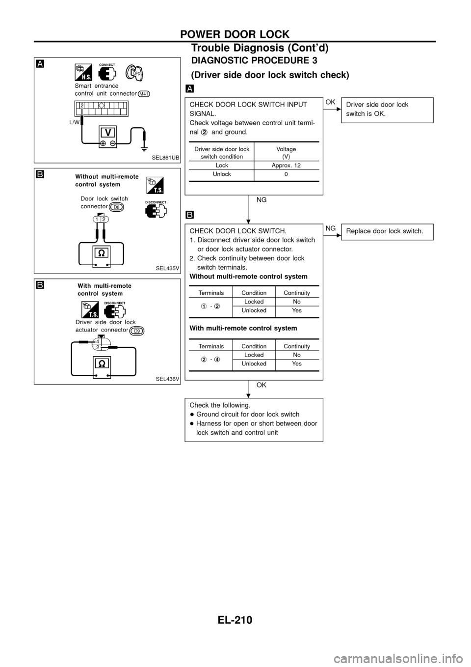
DIAGNOSTIC PROCEDURE 3
(Driver side door lock switch check)
CHECK DOOR LOCK SWITCH INPUT
SIGNAL.
Check voltage between control unit termi-
nalj
2and ground.
NG
cOK
Driver side door lock
switch is OK.
CHECK DOOR LOCK SWITCH.
1. Disconnect driver side door lock switch
or door lock actuator connector.
2. Check continuity between door lock
switch terminals.
Without multi-remote control system
With multi-remote control system
OK
cNG
Replace door lock switch.
Check the following.
+Ground circuit for door lock switch
+Harness for open or short between door
lock switch and control unit
Driver side door lock
switch conditionVoltage
(V)
Lock Approx. 12
Unlock 0
Terminals Condition Continuity
j
1-j2Locked No
Unlocked Yes
Terminals Condition Continuity
j
2-j4Locked No
Unlocked Yes
SEL861UB
SEL435V
SEL436V
.
.
POWER DOOR LOCK
Trouble Diagnosis (Cont'd)
EL-210