at control NISSAN PATROL 1998 Y61 / 5.G Electrical System User Guide
[x] Cancel search | Manufacturer: NISSAN, Model Year: 1998, Model line: PATROL, Model: NISSAN PATROL 1998 Y61 / 5.GPages: 326, PDF Size: 11.36 MB
Page 106 of 326
System Description
UNIFIED CONTROL METER
+Speedometer, odo/trip meter, tachometer, fuel gauge and water temperature gauge are controlled totally
by control unit combined with speedometer.
+Digital meter is adopted for odo/trip meter.*
*The record of the odo meter is kept even if the battery cable is disconnected. The record of the trip meter
is erased when the battery cable is disconnected.
+Odo/trip meter segment can be checked in diagnosis mode.
+Meter/gauge can be checked in diagnosis mode.
Note: Sub fuel gauge is not controlled by the control unit.
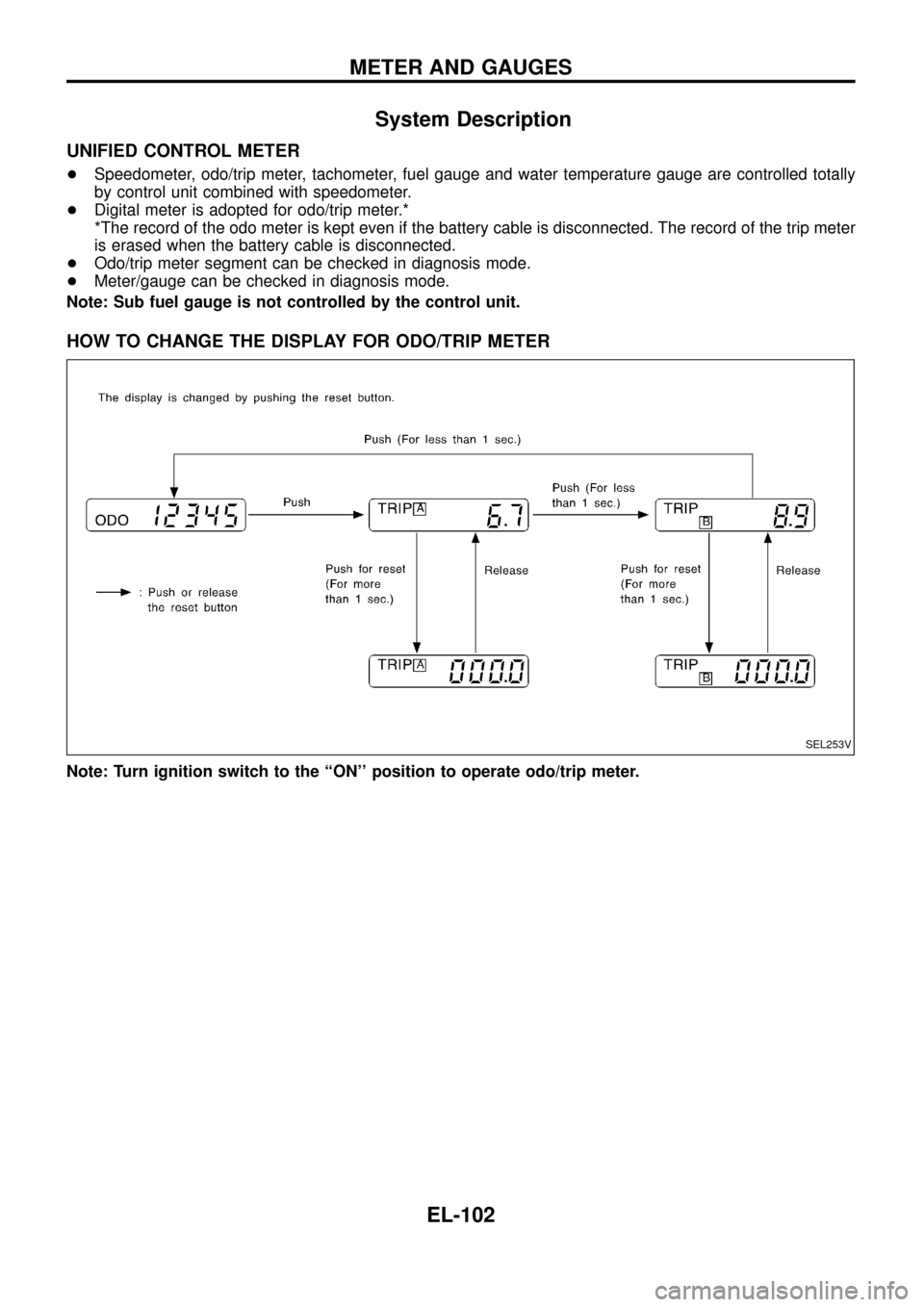
HOW TO CHANGE THE DISPLAY FOR ODO/TRIP METER
Note: Turn ignition switch to the ``ON'' position to operate odo/trip meter.
SEL253V
METER AND GAUGES
EL-102
Page 112 of 326
Meter/Gauge Operation and Odo/Trip Meter
Segment Check in Diagnosis Mode
DIAGNOSIS FUNCTION
+Odo/trip meter segment can be checked in diagnosis mode.
+Meters/gauges (except for sub fuel gauge) can be checked in
diagnosis mode.
HOW TO ALTERNATE DIAGNOSIS MODE
1. Turn ignition switch to ON and change odo/trip meter to ``TRIP
A'' or ``TRIP B''.
2. Turn ignition switch to OFF.
3. Turn ignition switch to ON when pushing odo/trip meter switch.
4. Con®rm that trip meter indicates ``000.0''.
5. Push odo/trip meter switch more than three times within 5 sec-
onds.
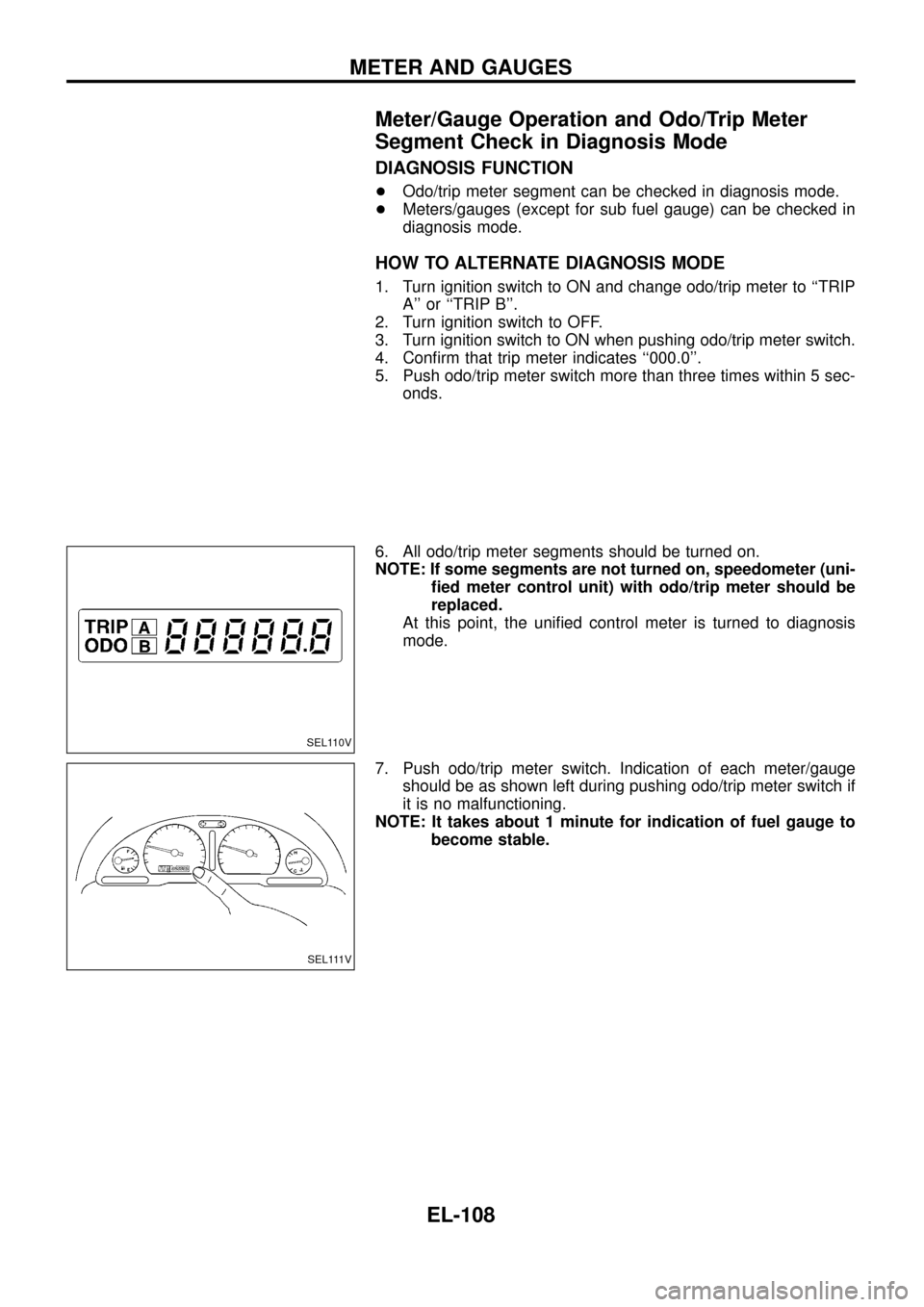
6. All odo/trip meter segments should be turned on.
NOTE: If some segments are not turned on, speedometer (uni-
®ed meter control unit) with odo/trip meter should be
replaced.
At this point, the uni®ed control meter is turned to diagnosis
mode.
7. Push odo/trip meter switch. Indication of each meter/gauge
should be as shown left during pushing odo/trip meter switch if
it is no malfunctioning.
NOTE: It takes about 1 minute for indication of fuel gauge to
become stable.
SEL110V
SEL111V
METER AND GAUGES
EL-108
Page 113 of 326
Flexible Print Circuit (FPC)
Tachometer, fuel gauge and water temperature gauge are con-
nected with uni®ed meter control unit (speedometer) by Flexible
Print Circuit (FPC) connector. When replace or remove and install
uni®ed control unit (speedometer), disconnect and connect FPC
connector according to the following steps.
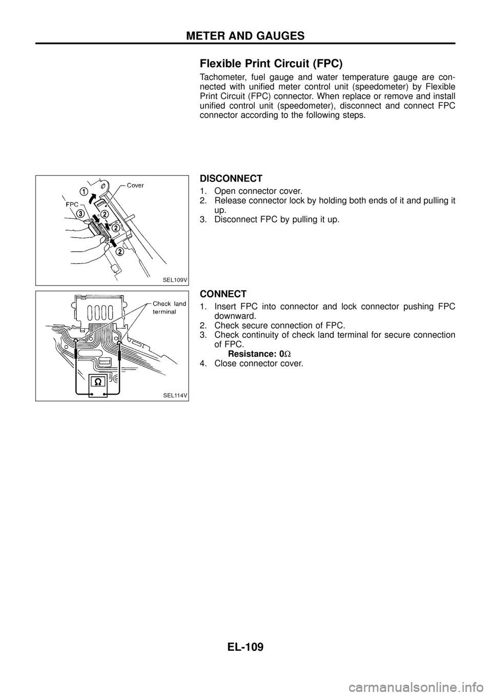
DISCONNECT
1. Open connector cover.
2. Release connector lock by holding both ends of it and pulling it
up.
3. Disconnect FPC by pulling it up.
CONNECT
1. Insert FPC into connector and lock connector pushing FPC
downward.
2. Check secure connection of FPC.
3. Check continuity of check land terminal for secure connection
of FPC.
Resistance: 0W
4. Close connector cover.
SEL109V
SEL114V
METER AND GAUGES
EL-109
Page 114 of 326
Trouble Diagnoses
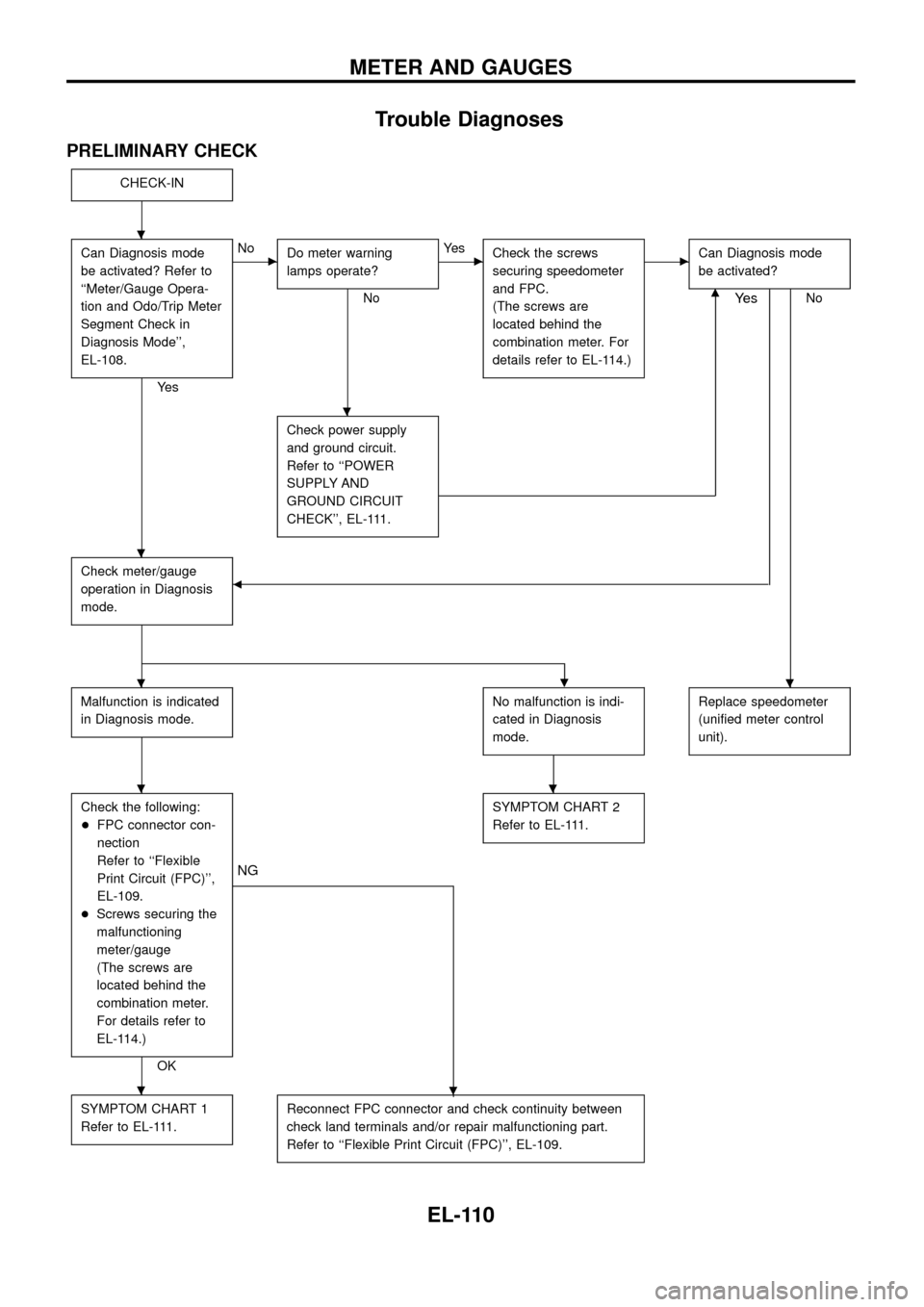
PRELIMINARY CHECK
CHECK-IN
Can Diagnosis mode
be activated? Refer to
``Meter/Gauge Opera-
tion and Odo/Trip Meter
Segment Check in
Diagnosis Mode'',
EL-108.
Ye s
cNo
Do meter warning
lamps operate?
No
cYe s
Check the screws
securing speedometer
and FPC.
(The screws are
located behind the
combination meter. For
details refer to EL-114.)cCan Diagnosis mode
be activated?
Nom
Check power supply
and ground circuit.
Refer to ``POWER
SUPPLY AND
GROUND CIRCUIT
CHECK'', EL-111.
Check meter/gauge
operation in Diagnosis
mode.b
Ye s
.
Malfunction is indicated
in Diagnosis mode.No malfunction is indi-
cated in Diagnosis
mode.Replace speedometer
(uni®ed meter control
unit).
Check the following:
+FPC connector con-
nection
Refer to ``Flexible
Print Circuit (FPC)'',
EL-109.
+Screws securing the
malfunctioning
meter/gauge
(The screws are
located behind the
combination meter.
For details refer to
EL-114.)
OK
.
NG
SYMPTOM CHART 2
Refer to EL-111.
SYMPTOM CHART 1
Refer to EL-111.Reconnect FPC connector and check continuity between
check land terminals and/or repair malfunctioning part.
Refer to ``Flexible Print Circuit (FPC)'', EL-109.
.
.
.
..
..
.
METER AND GAUGES
EL-110
Page 115 of 326
SYMPTOM CHART
Symptom chart 1 (Malfunction is indicated in Diagnosis mode)
Symptom Possible causes Repair order
Speedometer and/or odo/trip
meter indicate(s) malfunction
in Diagnosis mode.+Speedometer (Uni®ed meter control unit)+Replace speedometer (uni®ed meter control unit).
Multiple meter/gauge indicate
malfunction in Diagnosis
mode.
One of tachometer/fuel gauge/
water temp. gauge indicates
malfunction in Diagnosis
mode.+Meter/Gauge
+Speedometer (Uni®ed meter control unit)1. Check resistance of meter/gauge indicating malfunction. If
the resistance is NG, replace the meter/gauge. Refer to
``METER/GAUGE RESISTANCE CHECK'', EL-114.
2. If the resistance is OK, replace speedometer (uni®ed meter
control unit).
Symptom chart 2 (No malfunction is indicated in Diagnosis mode)
Symptom Possible causes Repair order
Speedometer and odo/trip
meter are malfunctioning.1. Sensor
- Speedometer, Odo/Trip meter
2. FPC connector
3. Speedometer (Uni®ed meter control unit)1. Check vehicle speed sensor.
INSPECTION/VEHICLE SPEED SENSOR (Refer to EL-112.)
2. Check FPC connector. Refer to ``Flexible Print Circuit
(FPC)'', EL-109.
3. Replace speedometer (uni®ed meter control unit).
Multiple meter/gauge are mal-
functioning. (except
speedometer, odo/trip meter)1. FPC connector
2. Speedometer (Uni®ed meter control unit)1. Check FPC connector. Refer to ``Flexible Print Circuit
(FPC)'', EL-109.
2. Replace speedometer (uni®ed meter control unit).
One of tachometer/fuel gauge/
water temp. gauge is malfunc-
tioning.1. Sensor/Engine revolution signal
- Tachometer
- Fuel gauge
- Water temp. gauge
2. FPC connector
3. Speedometer (Uni®ed meter control unit)1. Check the sensor for malfunctioning meter/gauge.
INSPECTION/ENGINE REVOLUTION SIGNAL (Refer to
EL-113.)
INSPECTION/FUEL TANK GAUGE (Refer to EL-113.)
INSPECTION/THERMAL TRANSMITTER (Refer to EL-114.)
2. Check FPC connector. Refer to ``Flexible Print Circuit
(FPC)'', EL-109.
3. Replace speedometer (uni®ed meter control unit).
Before starting trouble diagnoses above, perform PRELIMINARY CHECK, EL-110.
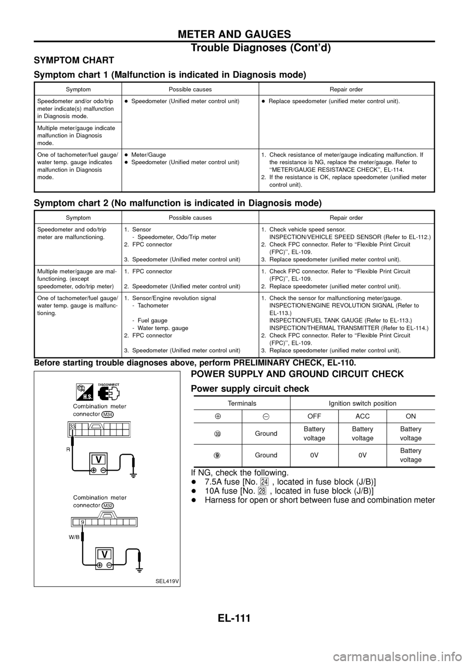
POWER SUPPLY AND GROUND CIRCUIT CHECK
Power supply circuit check
Terminals Ignition switch position
Å@OFF ACC ON
j
33GroundBattery
voltageBattery
voltageBattery
voltage
j
9Ground 0V 0VBattery
voltage
If NG, check the following.
+7.5A fuse [No.
24, located in fuse block (J/B)]
+10A fuse [No.
28, located in fuse block (J/B)]
+Harness for open or short between fuse and combination meter
SEL419V
METER AND GAUGES
Trouble Diagnoses (Cont'd)
EL-111
Page 139 of 326
System Description
The warning chime is combined with the smart entrance control unit.
Both the ignition key and light warning chime will not sound, when ignition switch in the ON or START posi-
tion. (When power supply exists at smart entrance control unit terminalj
12.)
IGNITION KEY WARNING CHIME
With the key in the ignition key cylinder, the ignition switch in the OFF or ACC position, and the driver's door
open, the warning chime will sound. A battery positive voltage is supplied
+from key switch terminalj
1
+to smart entrance control unit terminalj1.
Ground is supplied
+through driver side door switch
+to smart entrance control unit terminalj
7.
LIGHT WARNING CHIME
With ignition switch in the OFF or ACC position, driver's door open, and lighting switch in 1ST or 2ND position,
warning chime will sound. A battery positive voltage is supplied
+from lighting switch terminalj
12or daytime light control unit
+to smart entrance control unit terminalj
14.
Ground is supplied
+through driver side door switch
+to smart entrance control unit terminalj
7.
WARNING CHIME
EL-135
Page 142 of 326
Trouble Diagnoses
SYMPTOM CHART
REFERENCE PAGE EL-138 EL-139 EL-139
SYMPTOM
DIAGNOSTIC PROCEDURE 1
(Lighting switch input signal check)
DIAGNOSTIC PROCEDURE 2
(Key switch input signal check)
DIAGNOSTIC PROCEDURE 3
Light warning chime does not acti-
vate.XX
Ignition key warning chime does not
activate.XX
All warning chimes do not activate.X
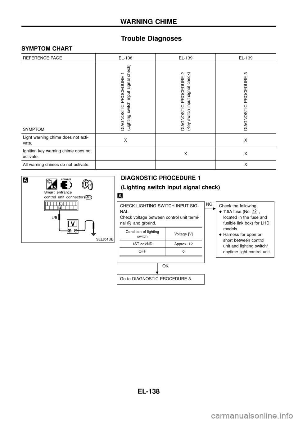
DIAGNOSTIC PROCEDURE 1
(Lighting switch input signal check)
CHECK LIGHTING SWITCH INPUT SIG-
NAL.
Check voltage between control unit termi-
nalj
14and ground.
OK
cNG
Check the following.
+7.5A fuse (No.
42,
located in the fuse and
fusible link box) for LHD
models
+Harness for open or
short between control
unit and lighting switch/
daytime light control unit
Go to DIAGNOSTIC PROCEDURE 3.
Condition of lighting
switchVoltage [V]
1ST or 2ND Approx. 12
OFF 0
SEL851UB
.
WARNING CHIME
EL-138
Page 143 of 326
DIAGNOSTIC PROCEDURE 2
(Key switch input signal check)
CHECK KEY SWITCH INPUT SIGNAL.
Check voltage between control unit termi-
nalj
1and ground.
OK
cNG
Check the following.
+Key switch
Refer to ``Electrical Com-
ponents Inspection'' (EL-
140).
+7.5A fuse [No.
24,
located in fuse block
(J/B)]
+Harness for open or
short between key
switch and fuse
+Harness for open or
short between control
unit and key switch
Go to DIAGNOSTIC PROCEDURE 3.
Condition of key switch Voltage [V]
Key is inserted. Approx. 12
Key is withdrawn. 0
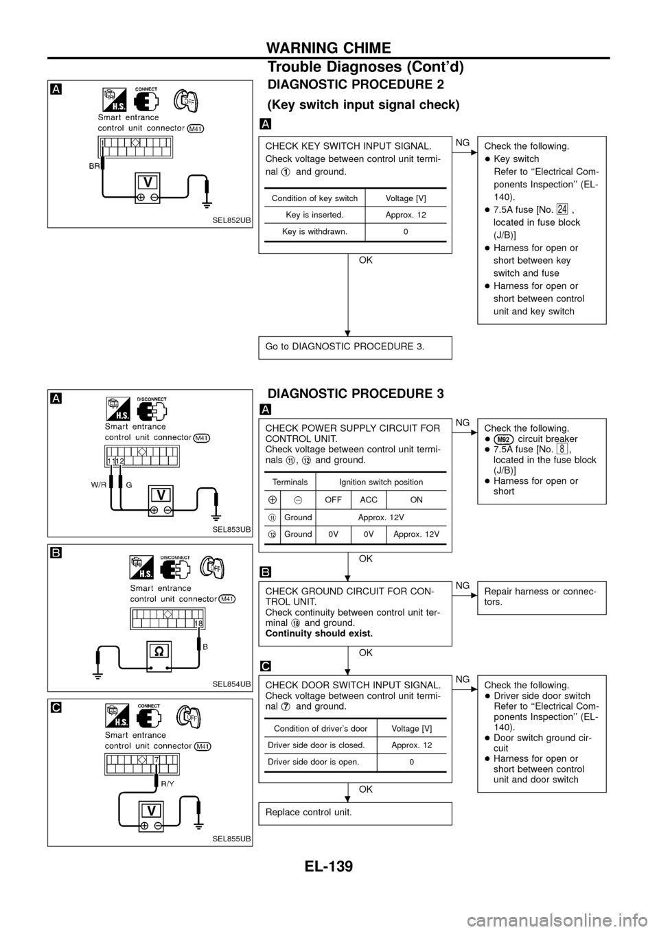
DIAGNOSTIC PROCEDURE 3
CHECK POWER SUPPLY CIRCUIT FOR
CONTROL UNIT.
Check voltage between control unit termi-
nalsj
11,j12and ground.
OK
cNG
Check the following.
+
M92circuit breaker
+7.5A fuse [No.8,
located in the fuse block
(J/B)]
+Harness for open or
short
CHECK GROUND CIRCUIT FOR CON-
TROL UNIT.
Check continuity between control unit ter-
minalj
18and ground.
Continuity should exist.
OK
cNG
Repair harness or connec-
tors.
CHECK DOOR SWITCH INPUT SIGNAL.
Check voltage between control unit termi-
nalj
7and ground.
OK
cNG
Check the following.
+Driver side door switch
Refer to ``Electrical Com-
ponents Inspection'' (EL-
140).
+Door switch ground cir-
cuit
+Harness for open or
short between control
unit and door switch
Replace control unit.
Terminals Ignition switch position
Å@OFF ACC ON
j
11Ground Approx. 12V
j
12Ground 0V 0V Approx. 12V
Condition of driver's door Voltage [V]
Driver side door is closed. Approx. 12
Driver side door is open. 0
SEL852UB
SEL853UB
SEL854UB
SEL855UB
.
.
.
.
WARNING CHIME
Trouble Diagnoses (Cont'd)
EL-139
Page 145 of 326
System Description
WIPER OPERATION
The wiper switch is controlled by a lever built into the combination switch.
There are three wiper switch positions:
+LO speed
+HI speed
+INT (Intermittent)
With the ignition switch in the ACC or ON position, power is supplied
+through 20A fuse [No.
, located in the fuse block (J/B)]
+to wiper motor terminalj
4.
Low and high speed wiper operation
Ground is supplied to wiper switch terminalj
17through body grounds.
When the wiper switch is placed in the LO position, ground is supplied
+through terminalj
14of the wiper switch
+to wiper motor terminalj
2.
With power and ground supplied, the wiper motor operates at low speed.
When the wiper switch is placed in the HI position, ground is supplied
+through terminalj
16of the wiper switch
+to wiper motor terminalj
3.
With power and ground supplied, the wiper motor operates at high speed.
Auto stop operation
With wiper switch turned OFF, wiper motor will continue to operate until wiper arms reach windshield base.
When wiper arms are not located at base of windshield with wiper switch OFF, ground is provided
+from terminalj
14of the wiper switch
+to wiper motor terminalj
2, in order to continue wiper motor operation at low speed.
+through wiper ampli®er (OUTPUT) combined with wiper switch and (with intermittent wiper)
+through terminalj
13of wiper switch
+to wiper motor terminalj
5
+through terminalj6of the wiper motor, and
+through body grounds.
When wiper arms reach base of windshield, wiper motor terminalsj
4andj5are connected instead of ter-
minalsj
5andj6. Wiper motor will then stop wiper arms at the PARK position.
Intermittent operation
The wiper motor operates the wiper arms one time at low speed at a set interval of approximately 3 to 13
seconds. This feature is controlled by the wiper ampli®er (INT SW) combined with wiper switch.
When the wiper switch is placed in the INT position, ground is supplied to wiper ampli®er.
The desired interval time is input to wiper ampli®er (INT VR) from wiper volume switch combined with wiper
switch.
Then intermittent ground is supplied
+to wiper motor terminalj
2
+from terminalj14of wiper switch
+through wiper ampli®er (OUTPUT).
The wiper motor operates at low speed at the desired interval.
WASHER OPERATION
With the ignition switch in the ACC or ON position, power is supplied
+through 20A fuse [No.
, located in the fuse block (J/B)]
+to washer motor terminalj
2.
When the lever is pulled to the WASH position, ground is supplied through wiper switch
+to washer motor terminalj
1, and
+to wiper ampli®er (WASH SW) combined with wiper switch.
With power and ground supplied, the washer motor operates.
When the lever is pulled to the WASH position for one second or more, the wiper motor operates at low speed
for approximately 3 seconds to clean windshield. This feature is controlled by the wiper ampli®er in the same
manner as the intermittent operation.
FRONT WIPER AND WASHER
EL-141
Page 149 of 326
System Description
WIPER OPERATION
The rear wiper switch is controlled by a ring built into the combination switch.
There are two wiper switch positions:
+ON (LO speed)
+INT (Intermittent)
With the ignition switch in the ON position, power is supplied
+through 10A fuse (No.
18, located in the fuse block)
+to rear wiper motor terminalj
4, and
+to rear wiper ampli®er terminalj
5.
Low speed wiper operation
Ground is supplied to rear wiper switch terminalj24through body grounds.
When the rear wiper is placed in the ON position, ground is supplied
+through rear wiper switch terminalj
22
+to rear wiper relay terminalj6.
Then ground is supplied
+to rear wiper motor terminalj
1
+through rear wiper ampli®er terminalsj2andj3.
With power and ground supplied, the wiper motor operates.
Auto stop operation
With the rear wiper switch turned OFF, rear wiper motor will continue to operate until wiper arm reaches rear
window base.
When wiper arm is not located at base of rear window with rear wiper switch OFF, ground is supplied
+to rear wiper motor terminalj
1
+through rear wiper ampli®er terminalsj2,j7and
+through rear wiper motor terminalj
3, in order to continue rear wiper motor operation at low speed.
Ground is also supplied
+to rear wiper motor terminalj
2
+through body grounds.
When wiper arm reaches base of rear window, rear wiper motor terminalsj
3andj4are connected instead
of terminalsj
2andj3. Rear wiper motor will then stop wiper arm at the PARK position.
Intermittent operation
The rear wiper motor operates the wiper arm one time at low speed at an interval of approximately 7 sec-
onds.
When the rear wiper switch is placed in the INT position, ground is supplied
+to rear wiper ampli®er terminalj
1
+through rear wiper switch terminalj21.
Then the rear wiper motor operates intermittently in the same manner as the low speed wiper operation.
WASHER OPERATION
With the ignition switch in the ACC or ON position, power is supplied
+through 10A fuse (No.
18, located in the fuse block)
+to rear washer motor terminalj
2.
When the ring is turned WASH position, ground is supplied
+to rear washer motor terminalj
1, and
+to rear wiper ampli®er terminalj
4
+through terminalj23of rear wiper switch.
With power and ground is supplied, the rear washer motor operates.
The rear wiper motor operates when the ring is turned to WASH position for one second or more and for
approximately 3 seconds after the ring is released. This feature is controlled by the rear wiper ampli®er in the
same manner as the low speed wiper operation.
REAR WIPER AND WASHER
EL-145