at control NISSAN PATROL 1998 Y61 / 5.G Electrical System Owner's Guide
[x] Cancel search | Manufacturer: NISSAN, Model Year: 1998, Model line: PATROL, Model: NISSAN PATROL 1998 Y61 / 5.GPages: 326, PDF Size: 11.36 MB
Page 216 of 326
System Description
OUTLINE
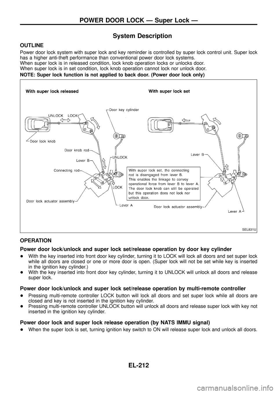
Power door lock system with super lock and key reminder is controlled by super lock control unit. Super lock
has a higher anti-theft performance than conventional power door lock systems.
When super lock is in released condition, lock knob operation locks or unlocks door.
When super lock is in set condition, lock knob operation cannot lock nor unlock door.
NOTE: Super lock function is not applied to back door. (Power door lock only)
OPERATION
Power door lock/unlock and super lock set/release operation by door key cylinder
+With the key inserted into front door key cylinder, turning it to LOCK will lock all doors and set super lock
while all doors are closed or one or more door is open. (Super lock will not be set while key is inserted
in the ignition key cylinder.)
+With the key inserted into front door key cylinder, turning it to UNLOCK will unlock all doors and release
super lock.
Power door lock/unlock and super lock set/release operation by multi-remote controller
+Pressing multi-remote controller LOCK button will lock all doors and set super lock while all doors are
closed and key is not inserted in the ignition key cylinder.
+Pressing multi-remote controller UNLOCK button will unlock all doors and release super lock with key not
inserted in the ignition key cylinder.
Power door lock and super lock release operation (by NATS IMMU signal)
+When the super lock is set, turning ignition key switch to ON will release super lock and unlock all doors.
SEL831U
POWER DOOR LOCK Ð Super Lock Ð
EL-212
Page 217 of 326
Power door lock/unlock operation by lock knob
+With lock knob on driver or passenger door setting to LOCK while all doors are closed will lock all doors.
When one or more door is opened, with lock knob on passenger door setting to LOCK will lock
passenger door only. (Power door lock system will not operate.)
+With lock knob on driver or passenger door setting to UNLOCK while all doors are closed will unlock all
doors.
Lock knob operation cannot control super lock.
Key reminder system
+If the ignition key is in the ignition key cylinder and any door is open, setting lock/unlock switch or lock
knob on driver or passenger door to ``LOCK'' locks the door once but then immediately unlocks all doors.
System initialisation
+System initialisation is required when battery cables are reconnected. Conduct one of the followings to
release super lock once;
Ð insert the key into ignition key cylinder and turn it to ON.
Ð LOCK/UNLOCK operation using door key cylinder.
POWER DOOR LOCK Ð Super Lock Ð
System Description (Cont'd)
EL-213
Page 227 of 326
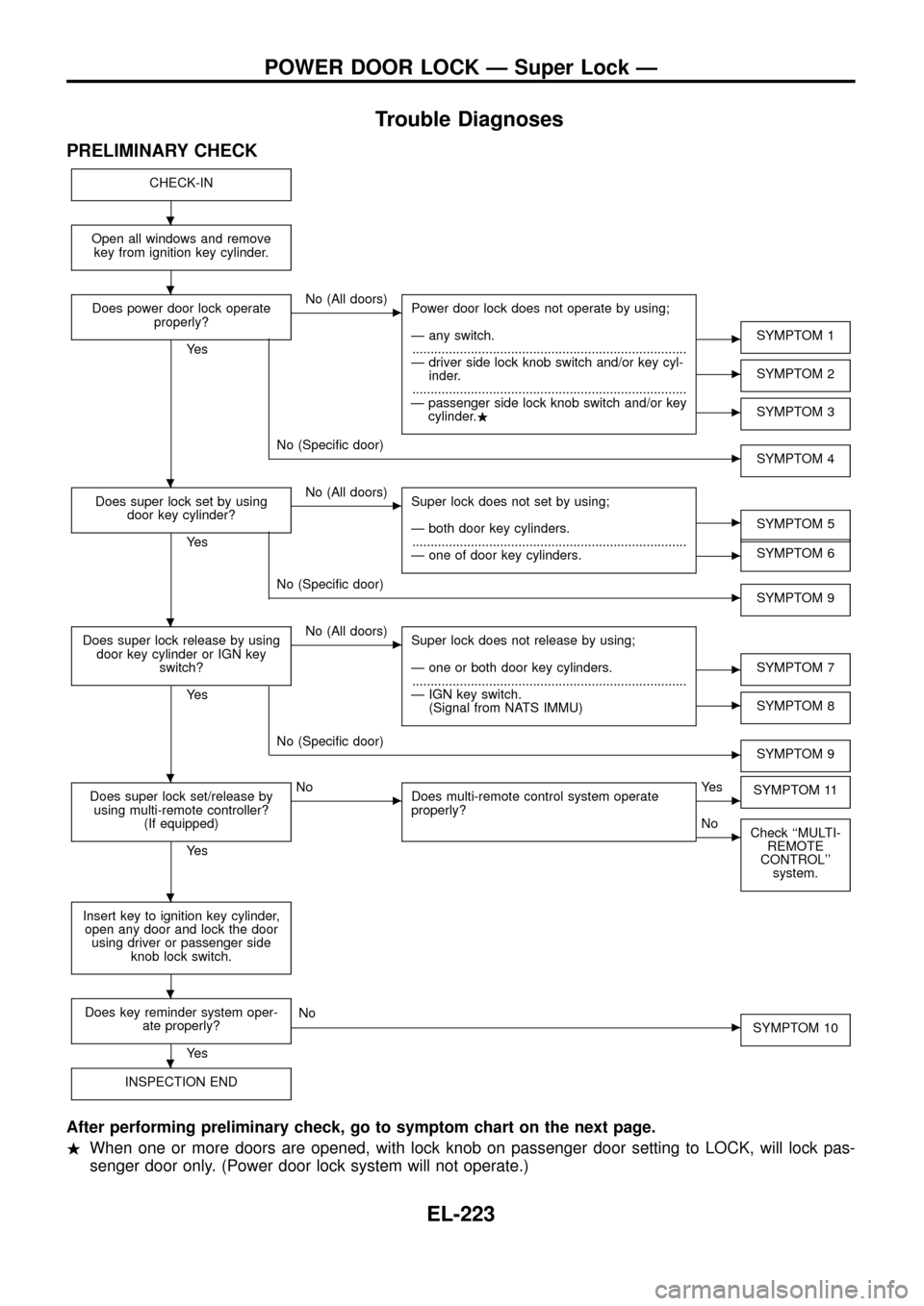
Trouble Diagnoses
PRELIMINARY CHECK
CHECK-IN
Open all windows and remove
key from ignition key cylinder.
Does power door lock operate
properly?
Ye s
cNo (All doors)
Power door lock does not operate by using;
Ð any switch.
...........................................................................
Ð driver side lock knob switch and/or key cyl-
inder.
...........................................................................
Ð passenger side lock knob switch and/or key
cylinder..
cSYMPTOM 1
cSYMPTOM 2
cSYMPTOM 3
cNo (Speci®c door)
SYMPTOM 4
Does super lock set by using
door key cylinder?
Ye s
cNo (All doors)
Super lock does not set by using;
Ð both door key cylinders.
...........................................................................
Ð one of door key cylinders.
cSYMPTOM 5
cSYMPTOM 6
cNo (Speci®c door)
SYMPTOM 9
Does super lock release by using
door key cylinder or IGN key
switch?
Ye s
cNo (All doors)
Super lock does not release by using;
Ð one or both door key cylinders.
...........................................................................
Ð IGN key switch.
(Signal from NATS IMMU)
cSYMPTOM 7
cSYMPTOM 8
cNo (Speci®c door)
SYMPTOM 9
Does super lock set/release by
using multi-remote controller?
(If equipped)
Ye s
cNo
Does multi-remote control system operate
properly?cYe s
SYMPTOM 11
cNo
Check ``MULTI-
REMOTE
CONTROL''
system.
Insert key to ignition key cylinder,
open any door and lock the door
using driver or passenger side
knob lock switch.
Does key reminder system oper-
ate properly?
Ye s
cNo
SYMPTOM 10
INSPECTION END
After performing preliminary check, go to symptom chart on the next page.
.When one or more doors are opened, with lock knob on passenger door setting to LOCK, will lock pas-
senger door only. (Power door lock system will not operate.)
.
.
.
.
.
.
.
.
POWER DOOR LOCK Ð Super Lock Ð
EL-223
Page 228 of 326
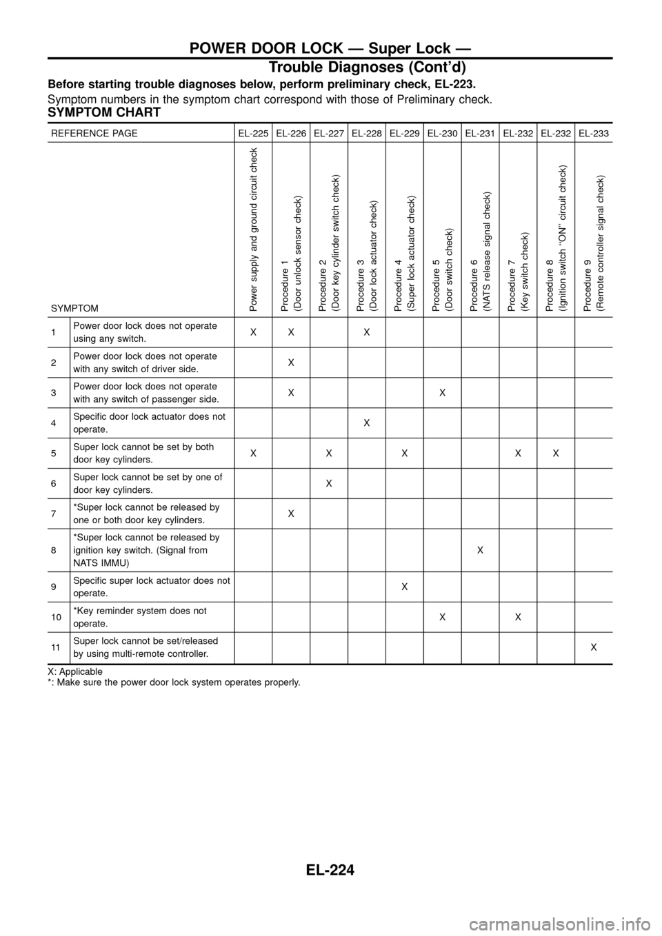
Before starting trouble diagnoses below, perform preliminary check, EL-223.
Symptom numbers in the symptom chart correspond with those of Preliminary check.
SYMPTOM CHART
REFERENCE PAGE EL-225 EL-226 EL-227 EL-228 EL-229 EL-230 EL-231 EL-232 EL-232 EL-233
SYMPTOM
Power supply and ground circuit check
Procedure 1
(Door unlock sensor check)
Procedure 2
(Door key cylinder switch check)
Procedure 3
(Door lock actuator check)
Procedure 4
(Super lock actuator check)
Procedure 5
(Door switch check)
Procedure 6
(NATS release signal check)
Procedure 7
(Key switch check)
Procedure 8
(Ignition switch ``ON'' circuit check)
Procedure 9
(Remote controller signal check)
1Power door lock does not operate
using any switch.XX X
2Power door lock does not operate
with any switch of driver side.X
3Power door lock does not operate
with any switch of passenger side.XX
4Speci®c door lock actuator does not
operate.X
5Super lock cannot be set by both
door key cylinders.XXX XX
6Super lock cannot be set by one of
door key cylinders.X
7*Super lock cannot be released by
one or both door key cylinders.X
8*Super lock cannot be released by
ignition key switch. (Signal from
NATS IMMU)X
9Speci®c super lock actuator does not
operate.X
10*Key reminder system does not
operate.XX
11Super lock cannot be set/released
by using multi-remote controller.X
X: Applicable
*: Make sure the power door lock system operates properly.
POWER DOOR LOCK Ð Super Lock Ð
Trouble Diagnoses (Cont'd)
EL-224
Page 230 of 326
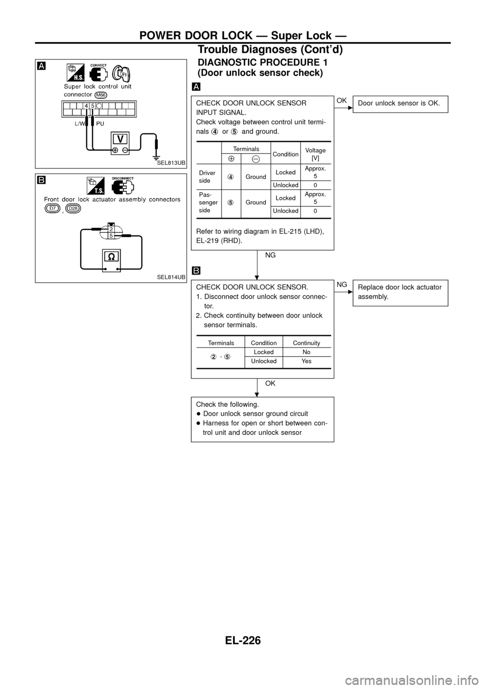
DIAGNOSTIC PROCEDURE 1
(Door unlock sensor check)
CHECK DOOR UNLOCK SENSOR
INPUT SIGNAL.
Check voltage between control unit termi-
nalsj
4orj5and ground.
Refer to wiring diagram in EL-215 (LHD),
EL-219 (RHD).
NG
cOK
Door unlock sensor is OK.
CHECK DOOR UNLOCK SENSOR.
1. Disconnect door unlock sensor connec-
tor.
2. Check continuity between door unlock
sensor terminals.
OK
cNG
Replace door lock actuator
assembly.
Check the following.
+Door unlock sensor ground circuit
+Harness for open or short between con-
trol unit and door unlock sensor
Terminals
ConditionVoltage
[V]
Å@
Driver
sidej4GroundLockedApprox.
5
Unlocked 0
Pas-
senger
sidej
5GroundLockedApprox.
5
Unlocked 0
Terminals Condition Continuity
j
2-j5Locked No
Unlocked Yes
SEL813UB
SEL814UB.
.
POWER DOOR LOCK Ð Super Lock Ð
Trouble Diagnoses (Cont'd)
EL-226
Page 231 of 326
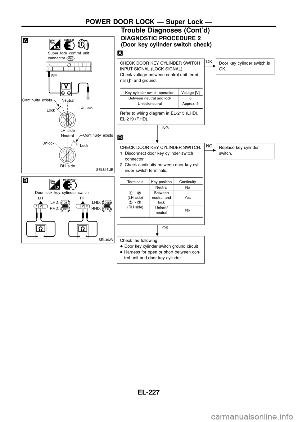
DIAGNOSTIC PROCEDURE 2
(Door key cylinder switch check)
CHECK DOOR KEY CYLINDER SWITCH
INPUT SIGNAL (LOCK SIGNAL).
Check voltage between control unit termi-
nalj
1and ground.
Refer to wiring diagram in EL-215 (LHD),
EL-219 (RHD).
NG
cOK
Door key cylinder switch is
OK.
CHECK DOOR KEY CYLINDER SWITCH.
1. Disconnect door key cylinder switch
connector.
2. Check continuity between door key cyl-
inder switch terminals.
OK
cNG
Replace key cylinder
switch.
Check the following.
+Door key cylinder switch ground circuit
+Harness for open or short between con-
trol unit and door key cylinder
Key cylinder switch operation Voltage [V]
Between neutral and lock 0
Unlock/neutral Approx. 5
Terminals Key position Continuity
j
1-j2(LH side)
j2-j3(RH side)Neutral No
Between
neutral and
lockYe s
Unlock/
neutralNo
SEL815UB
SEL492V
.
.
POWER DOOR LOCK Ð Super Lock Ð
Trouble Diagnoses (Cont'd)
EL-227
Page 232 of 326
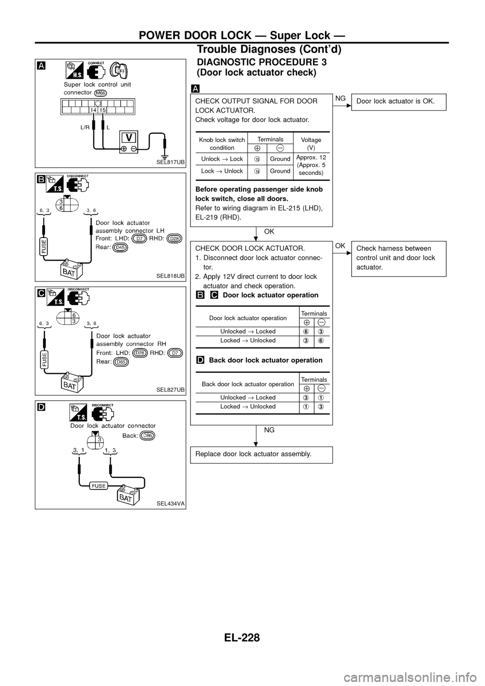
DIAGNOSTIC PROCEDURE 3
(Door lock actuator check)
CHECK OUTPUT SIGNAL FOR DOOR
LOCK ACTUATOR.
Check voltage for door lock actuator.
Before operating passenger side knob
lock switch, close all doors.
Refer to wiring diagram in EL-215 (LHD),
EL-219 (RHD).
OK
cNG
Door lock actuator is OK.
CHECK DOOR LOCK ACTUATOR.
1. Disconnect door lock actuator connec-
tor.
2. Apply 12V direct current to door lock
actuator and check operation.
Door lock actuator operation
Back door lock actuator operation
NG
cOK
Check harness between
control unit and door lock
actuator.
Replace door lock actuator assembly.
Knob lock switch
conditionTerminals
Voltage
(V)
Å@
Unlock®Lockj15GroundApprox. 12
(Approx. 5
seconds) Lock®Unlockj
14Ground
Door lock actuator operationTerminalsÅ@Unlocked®Lockedj6j3
Locked®Unlockedj3j6
Back door lock actuator operationTerminalsÅ@Unlocked®Lockedj3j1
Locked®Unlockedj1j3
SEL817UB
SEL818UB
SEL827UB
SEL434VA
.
.
POWER DOOR LOCK Ð Super Lock Ð
Trouble Diagnoses (Cont'd)
EL-228
Page 233 of 326
![NISSAN PATROL 1998 Y61 / 5.G Electrical System Owners Guide DIAGNOSTIC PROCEDURE 4
[Super lock actuator (in door lock actuator assembly)
check]
CHECK OUTPUT SIGNAL FOR SUPER
LOCK ACTUATOR.
Check voltage for super lock actuator.
Put the system in set condition NISSAN PATROL 1998 Y61 / 5.G Electrical System Owners Guide DIAGNOSTIC PROCEDURE 4
[Super lock actuator (in door lock actuator assembly)
check]
CHECK OUTPUT SIGNAL FOR SUPER
LOCK ACTUATOR.
Check voltage for super lock actuator.
Put the system in set condition](/img/5/616/w960_616-232.png)
DIAGNOSTIC PROCEDURE 4
[Super lock actuator (in door lock actuator assembly)
check]
CHECK OUTPUT SIGNAL FOR SUPER
LOCK ACTUATOR.
Check voltage for super lock actuator.
Put the system in set condition before
checking release signal.
Refer to wiring diagram in EL-215 (LHD),
EL-219 (RHD).
OK
cNG
Super lock actuator is OK.
CHECK SUPER LOCK ACTUATOR.
1. Disconnect door lock actuator assembly
connector.
2. Set lever A in Lock position.
3. Apply 12V direct current to door lock
actuator assembly and check operation.
NG
cOK
Check harness between
control unit and door lock
actuator assembly.
Replace door lock actuator assembly.
Door key cylinder
switch conditionTerminals
Voltage
(V)
Å@Lock (Set)j18Ground
Approx. 12
Unlock
(Released)j
13Ground
Super lock actua-
tor operationTerminals
Connection from
lever B to lever A
Å@Released®Setj1j4Disconnect
Set®Releasedj
4j1Connect
SEL819UB
SEL820UB
.
.
POWER DOOR LOCK Ð Super Lock Ð
Trouble Diagnoses (Cont'd)
EL-229
Page 234 of 326
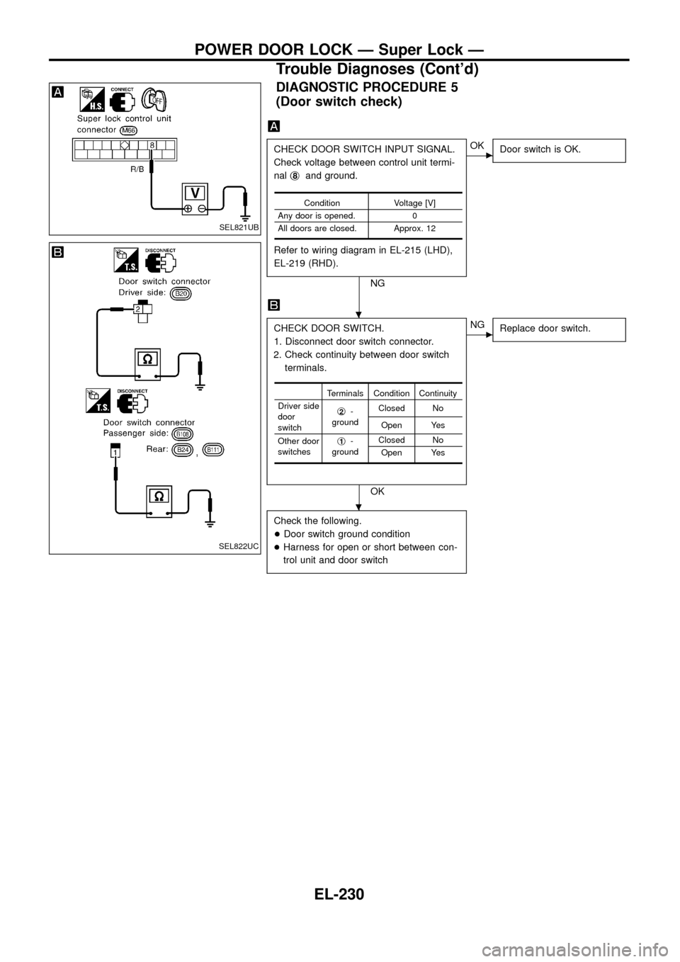
DIAGNOSTIC PROCEDURE 5
(Door switch check)
CHECK DOOR SWITCH INPUT SIGNAL.
Check voltage between control unit termi-
nalj
8and ground.
Refer to wiring diagram in EL-215 (LHD),
EL-219 (RHD).
NG
cOK
Door switch is OK.
CHECK DOOR SWITCH.
1. Disconnect door switch connector.
2. Check continuity between door switch
terminals.
OK
cNG
Replace door switch.
Check the following.
+Door switch ground condition
+Harness for open or short between con-
trol unit and door switch
Condition Voltage [V]
Any door is opened. 0
All doors are closed. Approx. 12
Terminals Condition Continuity
Driver side
door
switchj
2-
groundClosed No
Open Yes
Other door
switchesj
1-
groundClosed No
Open Yes
SEL821UB
SEL822UC
.
.
POWER DOOR LOCK Ð Super Lock Ð
Trouble Diagnoses (Cont'd)
EL-230
Page 235 of 326
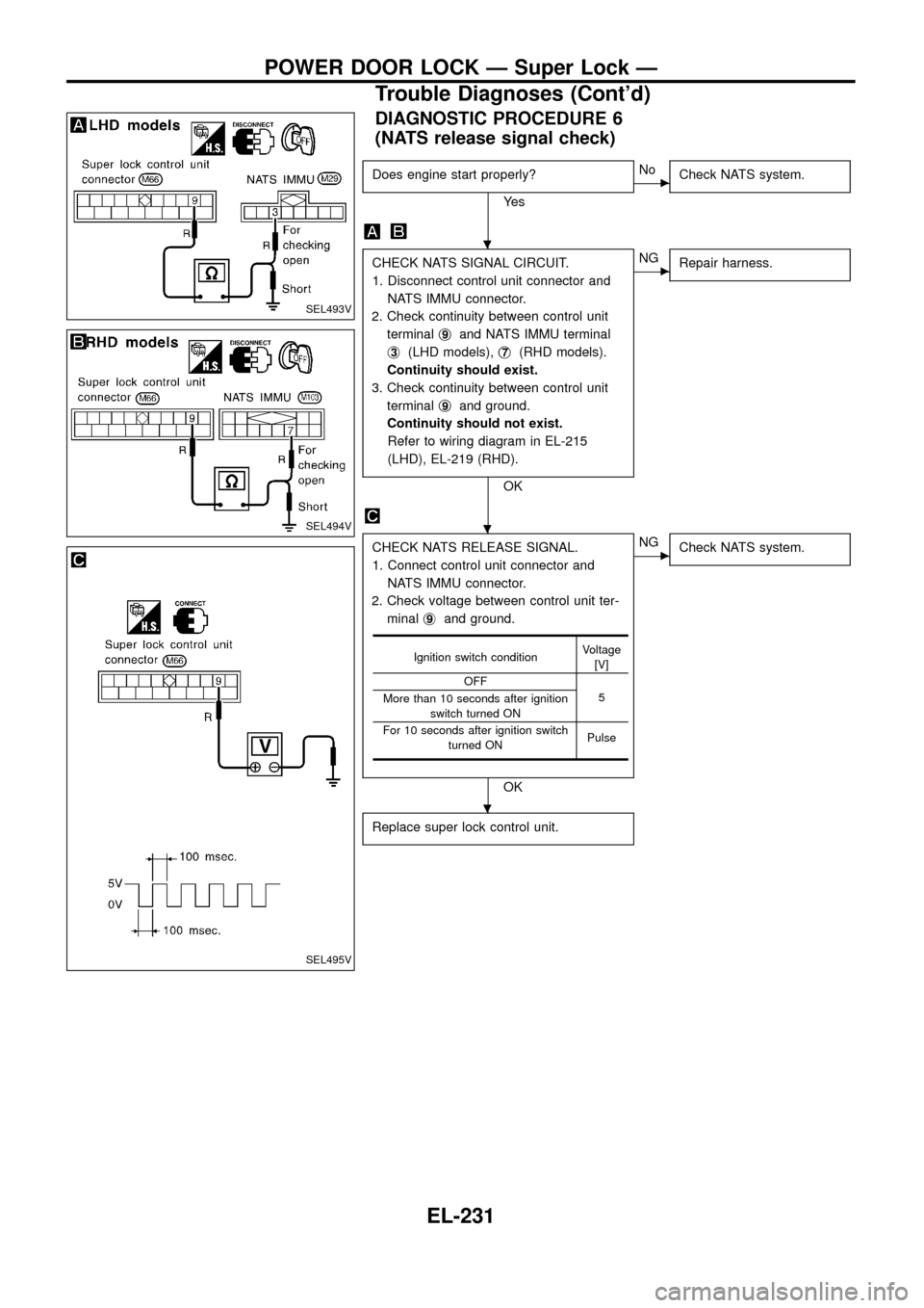
DIAGNOSTIC PROCEDURE 6
(NATS release signal check)
Does engine start properly?
Ye s
cNo
Check NATS system.
CHECK NATS SIGNAL CIRCUIT.
1. Disconnect control unit connector and
NATS IMMU connector.
2. Check continuity between control unit
terminalj
9and NATS IMMU terminal
j
3(LHD models),j7(RHD models).
Continuity should exist.
3. Check continuity between control unit
terminalj
9and ground.
Continuity should not exist.
Refer to wiring diagram in EL-215
(LHD), EL-219 (RHD).
OK
cNG
Repair harness.
CHECK NATS RELEASE SIGNAL.
1. Connect control unit connector and
NATS IMMU connector.
2. Check voltage between control unit ter-
minalj
9and ground.
OK
cNG
Check NATS system.
Replace super lock control unit.
Ignition switch conditionVoltage
[V]
OFF
5
More than 10 seconds after ignition
switch turned ON
For 10 seconds after ignition switch
turned ONPulse
SEL493V
SEL494V
SEL495V
.
.
.
POWER DOOR LOCK Ð Super Lock Ð
Trouble Diagnoses (Cont'd)
EL-231