NISSAN PATROL 1998 Y61 / 5.G Engine Control Workshop Manual
Manufacturer: NISSAN, Model Year: 1998, Model line: PATROL, Model: NISSAN PATROL 1998 Y61 / 5.GPages: 192, PDF Size: 4.28 MB
Page 131 of 192

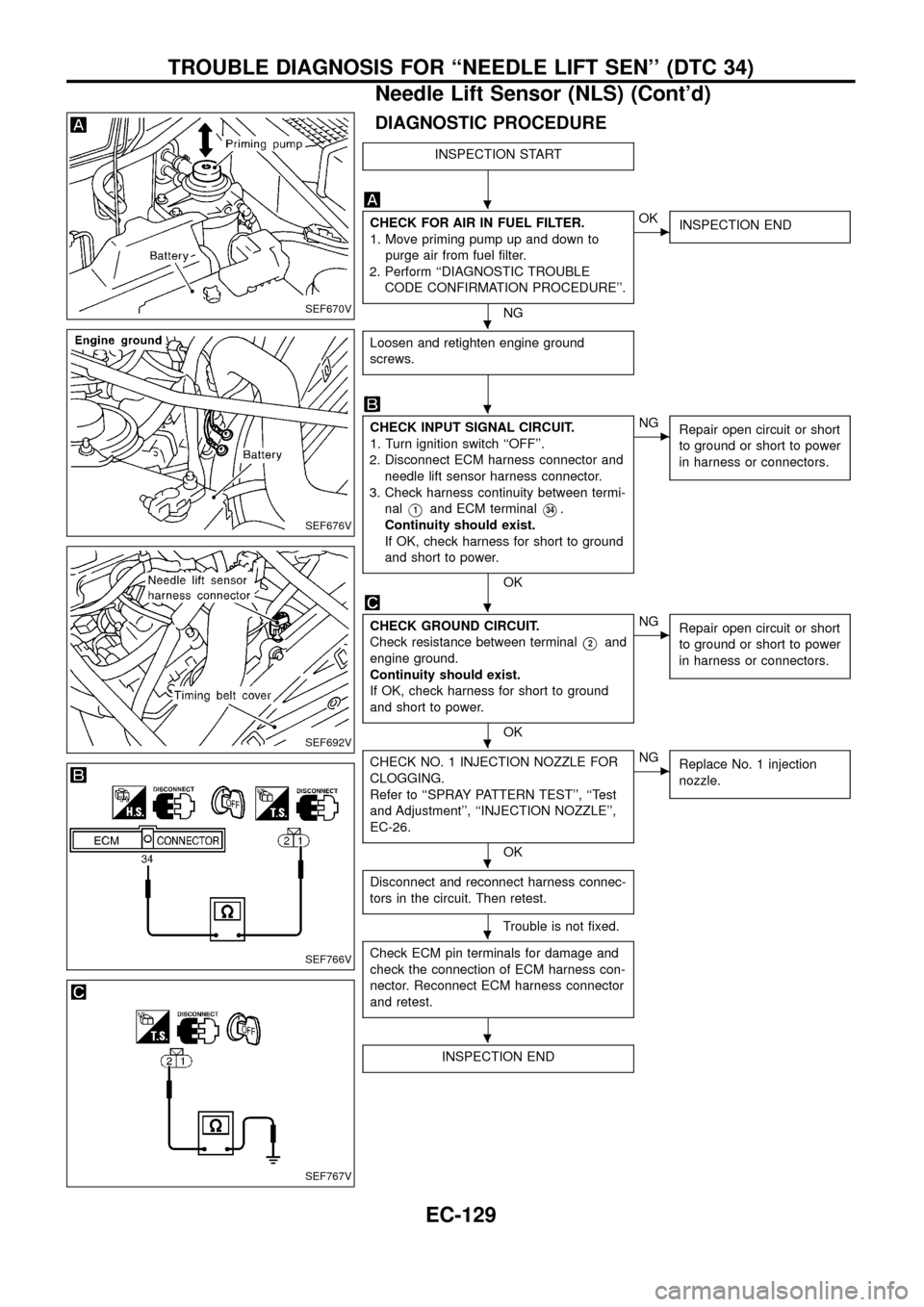
DIAGNOSTIC PROCEDURE
INSPECTION START
CHECK FOR AIR IN FUEL FILTER.
1. Move priming pump up and down to
purge air from fuel ®lter.
2. Perform ``DIAGNOSTIC TROUBLE
CODE CONFIRMATION PROCEDURE''.
NG
cOK
INSPECTION END
Loosen and retighten engine ground
screws.
CHECK INPUT SIGNAL CIRCUIT.
1. Turn ignition switch ``OFF''.
2. Disconnect ECM harness connector and
needle lift sensor harness connector.
3. Check harness continuity between termi-
nal
V1and ECM terminalV34.
Continuity should exist.
If OK, check harness for short to ground
and short to power.
OK
cNG
Repair open circuit or short
to ground or short to power
in harness or connectors.
CHECK GROUND CIRCUIT.
Check resistance between terminal
V2and
engine ground.
Continuity should exist.
If OK, check harness for short to ground
and short to power.
OK
cNG
Repair open circuit or short
to ground or short to power
in harness or connectors.
CHECK NO. 1 INJECTION NOZZLE FOR
CLOGGING.
Refer to ``SPRAY PATTERN TEST'', ``Test
and Adjustment'', ``INJECTION NOZZLE'',
EC-26.
OK
cNG
Replace No. 1 injection
nozzle.
Disconnect and reconnect harness connec-
tors in the circuit. Then retest.
Trouble is not ®xed.
Check ECM pin terminals for damage and
check the connection of ECM harness con-
nector. Reconnect ECM harness connector
and retest.
INSPECTION END
SEF670V
SEF676V
SEF692V
SEF766V
SEF767V
.
.
.
.
.
.
.
.
TROUBLE DIAGNOSIS FOR ``NEEDLE LIFT SEN'' (DTC 34)
Needle Lift Sensor (NLS) (Cont'd)
EC-129
Page 132 of 192

Fuel Cut Solenoid Valve
When the ignition switch is OFF, the ECM turns the fuel cut sole-
noid valve OFF (under this condition, no current ¯ows through the
fuel cut solenoid valve), shutting off fuel supply.
When the engine is not operating due to trouble, the fuel cut sole-
noid valve may or may not be OFF even when the ignition switch
is ON.
CONSULT REFERENCE VALUE IN DATA MONITOR MODE
Remarks: Speci®cation data are reference values.
MONITOR ITEM CONDITION SPECIFICATION
DECELER F/CUT+Engine: After warming upIdle OFF
When accelerator pedal is released
quickly with engine speed at 3,000
rpm or more.ON
FUEL CUT S/V+Ignition switch: ON®OFF ON®OFF
ECM TERMINALS AND REFERENCE VALUE
Remarks: Speci®cation data are reference values and are measured between each terminal andV43(ECCS
ground) with a voltmeter.
TER-
MINAL
NO.WIRE
COLORITEM CONDITIONDATA
(DC Voltage and Pulse
Signal)
4 B/Y ECCS relay (Self-shutoff)Ignition switch ``ON''
Ignition switch ``OFF''
For a few seconds after turning ignition switch
``OFF''0 - 1.5V
Ignition switch ``OFF''
A few seconds passed after turning ignition
switch ``OFF''BATTERY VOLTAGE
(11 - 14V)
56
61W Power supply for ECM Ignition switch ``ON''
BATTERY VOLTAGE
(11 - 14V)
11 3
11 5R/W Fuel cut solenoid valveIgnition switch ``OFF''
Approximately 0V
Ignition switch ``ON''
BATTERY VOLTAGE
(11 - 14V)
11 6
11 7W Power supply for ECM Ignition switch ``ON''
BATTERY VOLTAGE
(11 - 14V)
SEF667S
TROUBLE DIAGNOSIS FOR ``FUEL CUT S/V 1'' (DTC 36),
``FCV SHORT'' (DTC 37), ``FUEL CUT S/V 2'' (DTC 38)
EC-130
Page 133 of 192

ON BOARD DIAGNOSIS LOGIC
Diagnostic
Trouble
Code No.Malfunction is detected when ...Check Items
(Possible Cause)
36, 37, 38+Fuel cut solenoid valve circuit is malfunctioning.+Main power supply circuit (ECM terminals
11 6,11 7)
and fuse
+Harness or connectors
(The solenoid valve circuit is open or shorted.)
+Fuel cut solenoid valve
+ECM
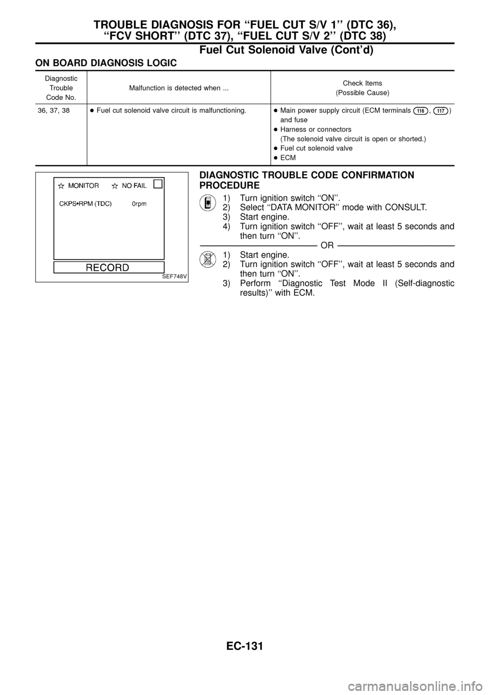
DIAGNOSTIC TROUBLE CODE CONFIRMATION
PROCEDURE
1) Turn ignition switch ``ON''.
2) Select ``DATA MONITOR'' mode with CONSULT.
3) Start engine.
4) Turn ignition switch ``OFF'', wait at least 5 seconds and
then turn ``ON''.
-------------------------------------------------------------------------------------------------------------------------------------------------------------------------------------------------------------------------------------------------------OR-------------------------------------------------------------------------------------------------------------------------------------------------------------------------------------------------------------------------------------------------------
1) Start engine.
2) Turn ignition switch ``OFF'', wait at least 5 seconds and
then turn ``ON''.
3) Perform ``Diagnostic Test Mode II (Self-diagnostic
results)'' with ECM.
SEF748V
TROUBLE DIAGNOSIS FOR ``FUEL CUT S/V 1'' (DTC 36),
``FCV SHORT'' (DTC 37), ``FUEL CUT S/V 2'' (DTC 38)
Fuel Cut Solenoid Valve (Cont'd)
EC-131
Page 134 of 192

TEC434
TROUBLE DIAGNOSIS FOR ``FUEL CUT S/V 1'' (DTC 36),
``FCV SHORT'' (DTC 37), ``FUEL CUT S/V 2'' (DTC 38)
Fuel Cut Solenoid Valve (Cont'd)
EC-132
Page 135 of 192

DIAGNOSTIC PROCEDURE
INSPECTION START
CHECK POWER SUPPLY FOR ECM.
Check power supply circuit. Refer to
EC-63.
OK
CHECK OUTPUT SIGNAL CIRCUIT.
1. Turn ignition switch ``ON''.
2. Select ``FUEL CUT SOL/V'' in
``ACTIVE TEST'' mode with
CONSULT.
3. Touch ``ON'' and ``OFF'' alter-
nately.
4. Check that operating sound is
emitted.
--------------------------------------------------------------------------------------------------------------------------------------OR--------------------------------------------------------------------------------------------------------------------------------------
1. Turn ignition switch ``OFF''.
2. Disconnect ECM harness con-
nector and electronic fuel injec-
tion pump harness connector.
3. Check harness continuity
between terminal
V4and ECM
terminals
11 3,11 5.
Continuity should exist.
If OK, check harness for short to
ground and short to power.
OK
cNG
Repair open circuit or short
to ground or short to power
in harness or connectors.
CHECK COMPONENT
(Fuel cut solenoid valve).
Refer to ``COMPONENT INSPECTION''
on next page.
OK
cNG
Replace fuel cut solenoid
valve.
Disconnect and reconnect harness con-
nectors in the circuit. Then retest.
Trouble is not ®xed.
Check ECM pin terminals for damage and
check the connection of ECM harness
connector. Reconnect ECM harness con-
nector and retest.
INSPECTION END
SEF860S
SEF682VA
SEF768V
.
.
.
.
.
.
TROUBLE DIAGNOSIS FOR ``FUEL CUT S/V 1'' (DTC 36),
``FCV SHORT'' (DTC 37), ``FUEL CUT S/V 2'' (DTC 38)
Fuel Cut Solenoid Valve (Cont'd)
EC-133
Page 136 of 192

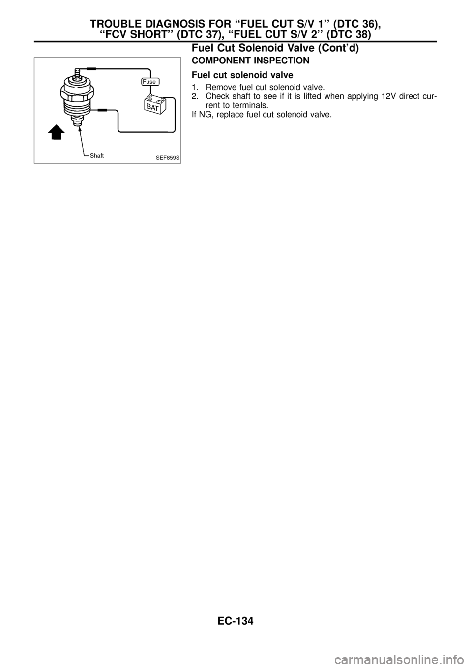
COMPONENT INSPECTION
Fuel cut solenoid valve
1. Remove fuel cut solenoid valve.
2. Check shaft to see if it is lifted when applying 12V direct cur-
rent to terminals.
If NG, replace fuel cut solenoid valve.
SEF859S
Fuse
Shaft
TROUBLE DIAGNOSIS FOR ``FUEL CUT S/V 1'' (DTC 36),
``FCV SHORT'' (DTC 37), ``FUEL CUT S/V 2'' (DTC 38)
Fuel Cut Solenoid Valve (Cont'd)
EC-134
Page 137 of 192

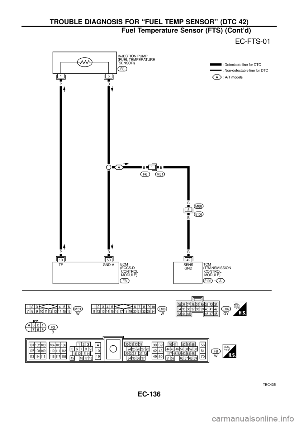
Fuel Temperature Sensor (FTS)
The fuel temperature sensor is used to detect the fuel temperature
in the injection pump. The sensor modi®es a voltage signal from the
ECM. The modi®ed signal returns to the ECM as the fuel tempera-
ture input. The sensor uses a thermistor which is sensitive to the
change in temperature. The electrical resistance of the thermistor
decreases as temperature increases.
Engine coolant tempera-
ture
ÉC (ÉF)Voltage
(V)Resistance
(kW)
þ20 (þ4) 4.6 13.67 - 16.37
20 (68) 3.5 2.306 - 2.568
60 (140) 1.8 0.538 - 0.624
80 (176) 1.2 0.289 - 0.344
ECM TERMINALS AND REFERENCE VALUE
Remarks: Speci®cation data are reference values and are measured between each terminal andV43(ECCS
ground) with a voltmeter.
TER-
MINAL
NO.WIRE
COLORITEM CONDITIONDATA
(DC Voltage and Pulse
Signal)
10 P Fuel temperature sensor Engine is running.
Approximately 0 - 4.8V
Output voltage varies with
fuel temperature.
50 B Sensors' groundEngine is running.
(Warm-up condition)
Idle speedApproximately 0V
ON BOARD DIAGNOSIS LOGIC
Diagnostic
Trouble Code
No.Malfunction is detected when ...Check Items
(Possible Cause)
42+An excessively high or low voltage from the sensor is
detected by ECM.+Harness or connectors
(The sensor circuit is open or shorted.)
+Fuel temperature sensor
DIAGNOSTIC TROUBLE CODE CONFIRMATION
PROCEDURE
1) Turn ignition switch ``ON''.
2) Select ``DATA MONITOR'' mode with CONSULT.
3) Wait at least 5 seconds.
-------------------------------------------------------------------------------------------------------------------------------------------------------------------------------------------------------------------------------------------------------OR-------------------------------------------------------------------------------------------------------------------------------------------------------------------------------------------------------------------------------------------------------
1) Turn ignition switch ``ON'' and wait at least 5 seconds.
2) Turn ignition switch ``OFF'', wait at least 5 seconds and
then turn ``ON''.
3) Perform ``Diagnostic Test Mode II (Self-diagnostic
results)'' with ECM.
SEF666S
SEF012P
SEF748V
TROUBLE DIAGNOSIS FOR ``FUEL TEMP SENSOR'' (DTC 42)
EC-135
Page 138 of 192

TEC435
TROUBLE DIAGNOSIS FOR ``FUEL TEMP SENSOR'' (DTC 42)
Fuel Temperature Sensor (FTS) (Cont'd)
EC-136
Page 139 of 192

DIAGNOSTIC PROCEDURE
INSPECTION START
CHECK POWER SUPPLY.
1. Turn ignition switch ``OFF''.
2. Disconnect electronic fuel injection
pump harness connector.
3. Turn ignition switch ``ON''.
4. Check voltage between terminal
V1
and ground with CONSULT or tester.
Voltage:
Approximately 5V
OK
cNG
Repair harness or connec-
tors.
CHECK GROUND CIRCUIT.
1. Turn ignition switch ``OFF''.
2. Check harness continuity between ter-
minal
V5and engine ground.
Continuity should exist.
If OK, check harness for short to
ground and short to power.
OK
cNG
Check the following.
+Harness connectors
F6,M51
+Harness connectors
M88,E106
+Harness for open or
short between ECM and
electronic fuel injection
pump
+Harness for open or
short between TCM and
electronic fuel injection
pump
If NG, repair open circuit or
short to ground or short to
power in harness or con-
nectors.
CHECK COMPONENT
(Fuel temperature sensor).
Refer to ``COMPONENT INSPECTION''
on next page.
OK
cNG
Take proper action.
Disconnect and reconnect harness con-
nectors in the circuits. Then retest.
Trouble is not ®xed.
Check ECM pin terminals for damage and
check the connection of ECM harness
connector. Reconnect ECM harness con-
nector and retest.
INSPECTION END
SEF682VB
SEF769V
SEF770V
.
.
.
.
.
.
TROUBLE DIAGNOSIS FOR ``FUEL TEMP SENSOR'' (DTC 42)
Fuel Temperature Sensor (FTS) (Cont'd)
EC-137
Page 140 of 192

COMPONENT INSPECTION
Fuel temperature sensor
Wait until fuel temperature sensor reaches room temperature.
Check resistance as shown in the ®gure.
Temperature ÉC (ÉF) Resistance kW
20 (68) 2.306 - 2.568
60 (140) 0.538 - 0.624
80 (176) 0.289 - 0.344
If NG, take proper action.SEF693V
SEF012P
TROUBLE DIAGNOSIS FOR ``FUEL TEMP SENSOR'' (DTC 42)
Fuel Temperature Sensor (FTS) (Cont'd)
EC-138