engine NISSAN PATROL 1998 Y61 / 5.G Engine Control Owner's Manual
[x] Cancel search | Manufacturer: NISSAN, Model Year: 1998, Model line: PATROL, Model: NISSAN PATROL 1998 Y61 / 5.GPages: 192, PDF Size: 4.28 MB
Page 33 of 192
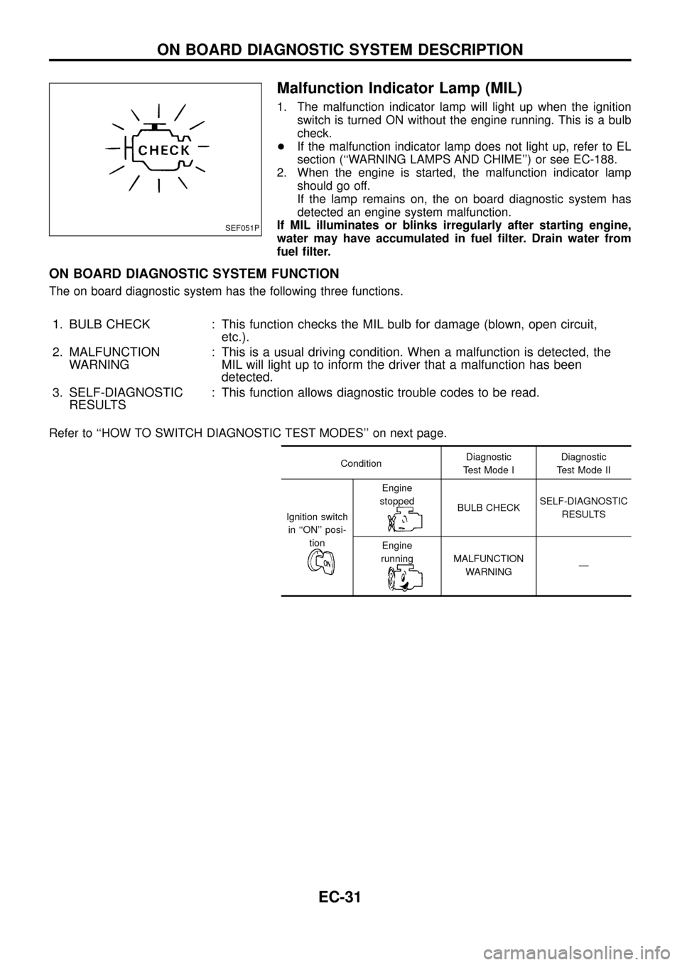
Malfunction Indicator Lamp (MIL)
1. The malfunction indicator lamp will light up when the ignition
switch is turned ON without the engine running. This is a bulb
check.
+If the malfunction indicator lamp does not light up, refer to EL
section (``WARNING LAMPS AND CHIME'') or see EC-188.
2. When the engine is started, the malfunction indicator lamp
should go off.
If the lamp remains on, the on board diagnostic system has
detected an engine system malfunction.
If MIL illuminates or blinks irregularly after starting engine,
water may have accumulated in fuel ®lter. Drain water from
fuel ®lter.
ON BOARD DIAGNOSTIC SYSTEM FUNCTION
The on board diagnostic system has the following three functions.
1. BULB CHECK : This function checks the MIL bulb for damage (blown, open circuit,
etc.).
2. MALFUNCTION
WARNING: This is a usual driving condition. When a malfunction is detected, the
MIL will light up to inform the driver that a malfunction has been
detected.
3. SELF-DIAGNOSTIC
RESULTS: This function allows diagnostic trouble codes to be read.
Refer to ``HOW TO SWITCH DIAGNOSTIC TEST MODES'' on next page.
ConditionDiagnostic
Test Mode IDiagnostic
Test Mode II
Ignition switch
in ``ON'' posi-
tion
Engine
stopped
BULB CHECKSELF-DIAGNOSTIC
RESULTS
Engine
running
MALFUNCTION
WARNINGÐ
SEF051P
ON BOARD DIAGNOSTIC SYSTEM DESCRIPTION
EC-31
Page 34 of 192
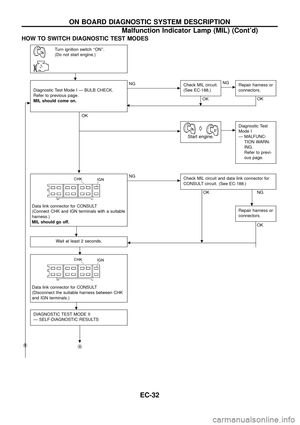
HOW TO SWITCH DIAGNOSTIC TEST MODES
Turn ignition switch ``ON''.
(Do not start engine.)
c
Diagnostic Test Mode I Ð BULB CHECK.
Refer to previous page.
MIL should come on.
.
OK
cNG
Check MIL circuit.
(See EC-188.)
OK
.
cNG
Repair harness or
connectors.
OK
b
cG
Start engine.
cDiagnostic Test
Mode I
Ð MALFUNC-
TION WARN-
ING.
Refer to previ-
ous page.
Data link connector for CONSULT
(Connect CHK and IGN terminals with a suitable
harness.)
MIL should go off.
cNG
Check MIL circuit and data link connector for
CONSULT circuit. (See EC-188.)
OK
.
NG
Repair harness or
connectors.
OK
Wait at least 2 seconds.
.b
Data link connector for CONSULT
(Disconnect the suitable harness between CHK
and IGN terminals.)
DIAGNOSTIC TEST MODE II
Ð SELF-DIAGNOSTIC RESULTS
.jBjA
.
.
.
.
ON BOARD DIAGNOSTIC SYSTEM DESCRIPTION
Malfunction Indicator Lamp (MIL) (Cont'd)
EC-32
Page 35 of 192
jB
m
jA
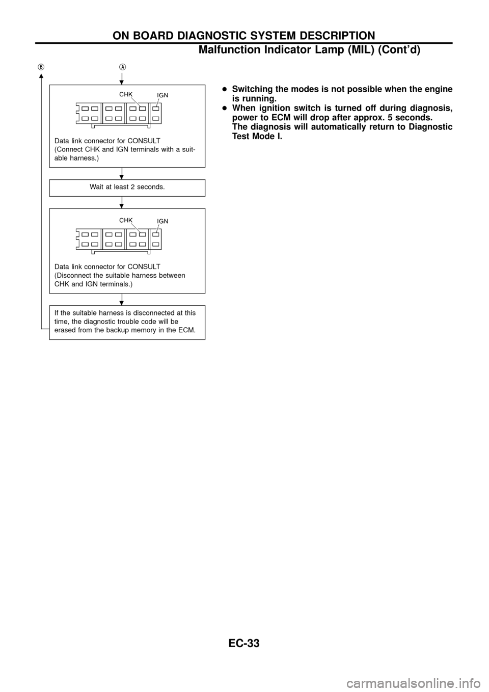
Data link connector for CONSULT
(Connect CHK and IGN terminals with a suit-
able harness.)
Wait at least 2 seconds.
Data link connector for CONSULT
(Disconnect the suitable harness between
CHK and IGN terminals.)
If the suitable harness is disconnected at this
time, the diagnostic trouble code will be
erased from the backup memory in the ECM.
+Switching the modes is not possible when the engine
is running.
+When ignition switch is turned off during diagnosis,
power to ECM will drop after approx. 5 seconds.
The diagnosis will automatically return to Diagnostic
Test Mode I..
.
.
.
ON BOARD DIAGNOSTIC SYSTEM DESCRIPTION
Malfunction Indicator Lamp (MIL) (Cont'd)
EC-33
Page 37 of 192
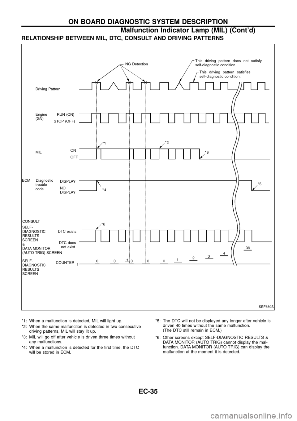
RELATIONSHIP BETWEEN MIL, DTC, CONSULT AND DRIVING PATTERNS
*1: When a malfunction is detected, MIL will light up.
*2: When the same malfunction is detected in two consecutive
driving patterns, MIL will stay lit up.
*3: MIL will go off after vehicle is driven three times without
any malfunctions.
*4: When a malfunction is detected for the ®rst time, the DTC
will be stored in ECM.*5: The DTC will not be displayed any longer after vehicle is
driven 40 times without the same malfunction.
(The DTC still remain in ECM.)
*6: Other screens except SELF-DIAGNOSTIC RESULTS &
DATA MONITOR (AUTO TRIG) cannot display the mal-
function. DATA MONITOR (AUTO TRIG) can display the
malfunction at the moment it is detected.
SEF659S
RUN (ON)
STOP (OFF)
ON
OFF
DISPLAY
NO
DISPLAY
DTC exists
DTC does
not exist
COUNTER Driving Pattern
Engine
(GN)
MIL
ECM Diagnostic
trouble
code
CONSULT
SELF-
DIAGNOSTIC
RESULTS
SCREEN
&
DATA MONITOR
(AUTO TRIG) SCREEN
SELF-
DIAGNOSTIC
RESULTS
SCREENNG DetectionThis driving pattern does not satisfy
self-diagnostic condition.
This driving pattern satis®es
self-diagnostic condition.
ON BOARD DIAGNOSTIC SYSTEM DESCRIPTION
Malfunction Indicator Lamp (MIL) (Cont'd)
EC-35
Page 38 of 192
CONSULT
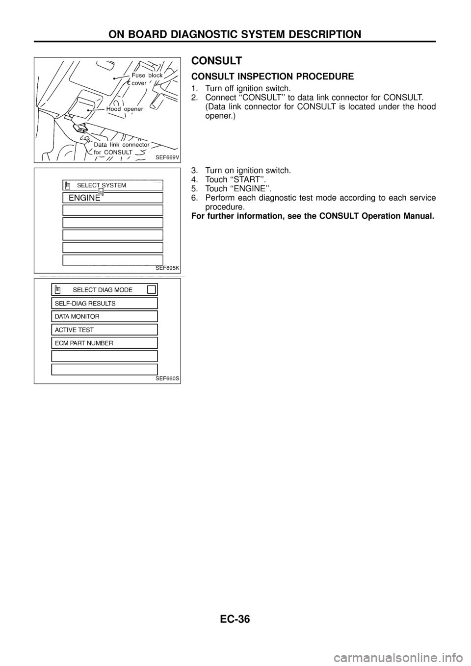
CONSULT INSPECTION PROCEDURE
1. Turn off ignition switch.
2. Connect ``CONSULT'' to data link connector for CONSULT.
(Data link connector for CONSULT is located under the hood
opener.)
3. Turn on ignition switch.
4. Touch ``START''.
5. Touch ``ENGINE''.
6. Perform each diagnostic test mode according to each service
procedure.
For further information, see the CONSULT Operation Manual.
SEF669V
SEF895K
SEF660S
ON BOARD DIAGNOSTIC SYSTEM DESCRIPTION
EC-36
Page 39 of 192
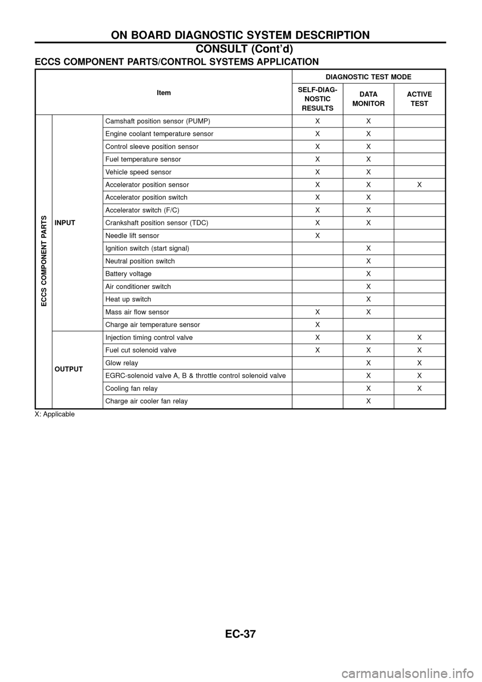
ECCS COMPONENT PARTS/CONTROL SYSTEMS APPLICATION
ItemDIAGNOSTIC TEST MODE
SELF-DIAG-
NOSTIC
RESULTSDATA
MONITORACTIVE
TEST
ECCS COMPONENT PARTS
INPUTCamshaft position sensor (PUMP) X X
Engine coolant temperature sensor X X
Control sleeve position sensor X X
Fuel temperature sensor X X
Vehicle speed sensor X X
Accelerator position sensor X X X
Accelerator position switch X X
Accelerator switch (F/C) X X
Crankshaft position sensor (TDC) X X
Needle lift sensor X
Ignition switch (start signal) X
Neutral position switch X
Battery voltage X
Air conditioner switch X
Heat up switch X
Mass air ¯ow sensor X X
Charge air temperature sensor X
OUTPUTInjection timing control valve X X X
Fuel cut solenoid valve X X X
Glow relayXX
EGRC-solenoid valve A, B & throttle control solenoid valve X X
Cooling fan relay X X
Charge air cooler fan relay X
X: Applicable
ON BOARD DIAGNOSTIC SYSTEM DESCRIPTION
CONSULT (Cont'd)
EC-37
Page 40 of 192
![NISSAN PATROL 1998 Y61 / 5.G Engine Control Owners Manual SELF-DIAGNOSTIC MODE
Regarding items detected in ``SELF-DIAG RESULTS mode, refer to ``DIAGNOSTIC TROUBLE CODE
INDEX, EC-1.
DATA MONITOR MODE
Monitored item
[Unit]ECM
input
signalsMain
signalsDescr NISSAN PATROL 1998 Y61 / 5.G Engine Control Owners Manual SELF-DIAGNOSTIC MODE
Regarding items detected in ``SELF-DIAG RESULTS mode, refer to ``DIAGNOSTIC TROUBLE CODE
INDEX, EC-1.
DATA MONITOR MODE
Monitored item
[Unit]ECM
input
signalsMain
signalsDescr](/img/5/617/w960_617-39.png)
SELF-DIAGNOSTIC MODE
Regarding items detected in ``SELF-DIAG RESULTS'' mode, refer to ``DIAGNOSTIC TROUBLE CODE
INDEX'', EC-1.
DATA MONITOR MODE
Monitored item
[Unit]ECM
input
signalsMain
signalsDescription Remarks
CKPSzRPM
(TDC) [rpm]
jj
+The engine speed computed from the
crankshaft position sensor (TDC) signal
is displayed.
CKPSzRPM
(REF) [rpm]
jj
+The engine speed [determined by the
time between pulses from the crankshaft
position sensor (TDC) signal] is dis-
played.
CMPSzRPM -
PUMP [rpm]
jj
+The engine speed computed from the
camshaft position sensor (PUMP) signal
is displayed.
COOLAN TEMP/S
[ÉC] or [ÉF]
jj
+The engine coolant temperature (deter-
mined by the signal voltage of the engine
coolant temperature sensor) is displayed.+When the engine coolant temperature
sensor is open or short-circuited, ECM
enters fail-safe mode. The engine cool-
ant temperature determined by the ECM
is displayed.
VHCL SPEED SE
[km/h] or [mph]
jj+The vehicle speed computed from the
vehicle speed sensor signal is displayed.
FUEL TEMP SEN
[ÉC] or [ÉF]
jj
+The fuel temperature (determined by the
signal voltage of the fuel temperature
sensor) is displayed.
ACCEL POS SEN [V]
jj+The accelerator position sensor signal
voltage is displayed.
FULL ACCEL SW
[ON/OFF]
jj+Indicates [ON/OFF] condition from the
accelerator position switch signal.
ACCEL SW (FC)
[OPEN/CLOSE]
jj+Indicates [OPEN/CLOSE] condition from
the accelerator switch (FC) signal.
OFF ACCEL SW
[ON/OFF]
jj+Indicates [ON/OFF] condition from the
accelerator position switch signal.
C/SLEEV POS/S [V]
jj+The control sleeve position sensor signal
voltage is displayed.
BATTERY VOLT [V]
jj+The power supply voltage of ECM is dis-
played.
P/N POSI SW
[ON/OFF]
jj+Indicates [ON/OFF] condition from the
park/neutral position switch signal.
START SIGNAL
[ON/OFF]
jj+Indicates [ON/OFF] condition from the
starter signal.+After starting the engine, [OFF] is dis-
played regardless of the starter signal.
NOTE:
Any monitored item that does not match the vehicle being diagnosed is deleted from the display automatically.
ON BOARD DIAGNOSTIC SYSTEM DESCRIPTION
CONSULT (Cont'd)
EC-38
Page 41 of 192
![NISSAN PATROL 1998 Y61 / 5.G Engine Control Owners Manual Monitored item
[Unit]ECM
input
signalsMain
signalsDescription Remarks
AIR COND SIG
[ON/OFF]
jj
+Indicates [ON/OFF] condition of the air
conditioner switch as determined by the
air conditioner signal.
NISSAN PATROL 1998 Y61 / 5.G Engine Control Owners Manual Monitored item
[Unit]ECM
input
signalsMain
signalsDescription Remarks
AIR COND SIG
[ON/OFF]
jj
+Indicates [ON/OFF] condition of the air
conditioner switch as determined by the
air conditioner signal.](/img/5/617/w960_617-40.png)
Monitored item
[Unit]ECM
input
signalsMain
signalsDescription Remarks
AIR COND SIG
[ON/OFF]
jj
+Indicates [ON/OFF] condition of the air
conditioner switch as determined by the
air conditioner signal.
IGN SW
[ON/OFF]
jj+Indicates [ON/OFF] condition from igni-
tion switch signal.
MAS AIR/FL SE [V]
jj+The signal voltage of the mass air ¯ow
sensor is displayed.+When the engine is stopped, a certain
value is indicated.
ACT INJ TIMG [É]
jj
+The actual injection timing angle deter-
mined by the ECM (an approximate
average angle between injection start
and end from TDC) is displayed.
INJ TIMG C/V [%]+Indicates the duty ratio of fuel injection
timing control valve.
DECELER F/CUT
[ON/OFF]
j
+Indicates [ON/OFF] condition from decel-
eration fuel cut signal.+When the accelerator pedal is released
quickly with engine speed at 3,000 rpm
or more, ``ON'' is displayed.
FUEL CUT S/V
[ON/OFF]
j
+The control condition of the fuel cut sole-
noid valve (determined by ECM accord-
ing to the input signal) is indicted.
+OFF ... Fuel cut solenoid valve is not
operating.
ON ... Fuel cut solenoid valve is operat-
ing.+When the fuel cut solenoid valve is not
operating, fuel is not supplied to injection
nozzles.
GLOW RLY [ON/OFF]
j
+The glow relay control condition (deter-
mined by ECM according to the input
signal) is displayed.
COOLING FAN
[LOW/HI/OFF]
j
+Indicates the control condition of the
cooling fans (determined by ECM
according to the input signal).
+LOW ... Operates at low speed.
HI ... Operates at high speed.
OFF ... Stopped.
I/C FAN RLY
[ON/OFF]
j
+Indicates the control condition of the
charge air cooler fan (determined by
ECM according to the input signals).
EGRC SOL/V A
[ON/OFF]+The control condition of the EGRC-sole-
noid valve A (determined by ECM
according to the input signal) is indi-
cated.
+OFF ... EGRC-solenoid valve A is not
operating.
ON ... EGRC-solenoid valve A is operat-
ing.
EGRC SOL/V B
[ON/OFF]+The control condition of the EGRC-sole-
noid valve B (determined by ECM
according to the input signal) is indi-
cated.
+OFF ... EGRC-solenoid valve B is not
operating.
ON ... EGRC-solenoid valve B is operat-
ing.
THROT RLY
[ON/OFF]+The control condition of the throttle con-
trol solenoid valve (determined by ECM
according to the input signal) is indi-
cated.
+OFF ... Throttle control solenoid valve is
not operating.
ON ... Throttle control solenoid valve is
operating.
ON BOARD DIAGNOSTIC SYSTEM DESCRIPTION
CONSULT (Cont'd)
EC-39
Page 42 of 192
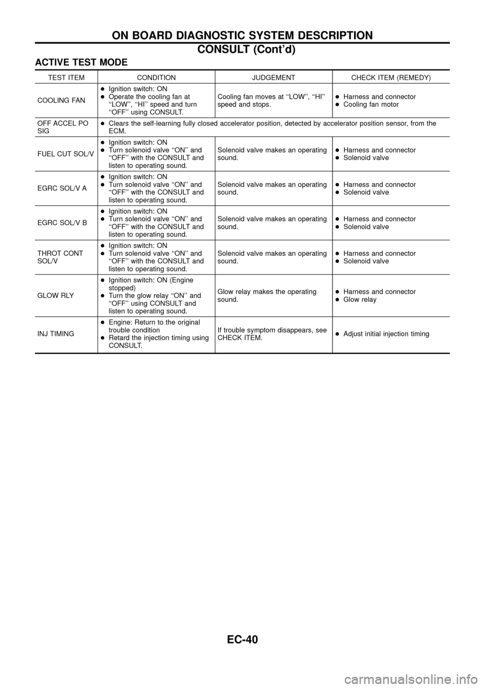
ACTIVE TEST MODE
TEST ITEM CONDITION JUDGEMENT CHECK ITEM (REMEDY)
COOLING FAN+Ignition switch: ON
+Operate the cooling fan at
``LOW'', ``HI'' speed and turn
``OFF'' using CONSULT.Cooling fan moves at ``LOW'', ``HI''
speed and stops.+Harness and connector
+Cooling fan motor
OFF ACCEL PO
SIG+Clears the self-learning fully closed accelerator position, detected by accelerator position sensor, from the
ECM.
FUEL CUT SOL/V+Ignition switch: ON
+Turn solenoid valve ``ON'' and
``OFF'' with the CONSULT and
listen to operating sound.Solenoid valve makes an operating
sound.+Harness and connector
+Solenoid valve
EGRC SOL/V A+Ignition switch: ON
+Turn solenoid valve ``ON'' and
``OFF'' with the CONSULT and
listen to operating sound.Solenoid valve makes an operating
sound.+Harness and connector
+Solenoid valve
EGRC SOL/V B+Ignition switch: ON
+Turn solenoid valve ``ON'' and
``OFF'' with the CONSULT and
listen to operating sound.Solenoid valve makes an operating
sound.+Harness and connector
+Solenoid valve
THROT CONT
SOL/V+Ignition switch: ON
+Turn solenoid valve ``ON'' and
``OFF'' with the CONSULT and
listen to operating sound.Solenoid valve makes an operating
sound.+Harness and connector
+Solenoid valve
GLOW RLY+Ignition switch: ON (Engine
stopped)
+Turn the glow relay ``ON'' and
``OFF'' using CONSULT and
listen to operating sound.Glow relay makes the operating
sound.+Harness and connector
+Glow relay
INJ TIMING+Engine: Return to the original
trouble condition
+Retard the injection timing using
CONSULT.If trouble symptom disappears, see
CHECK ITEM.+Adjust initial injection timing
ON BOARD DIAGNOSTIC SYSTEM DESCRIPTION
CONSULT (Cont'd)
EC-40
Page 44 of 192
Introduction
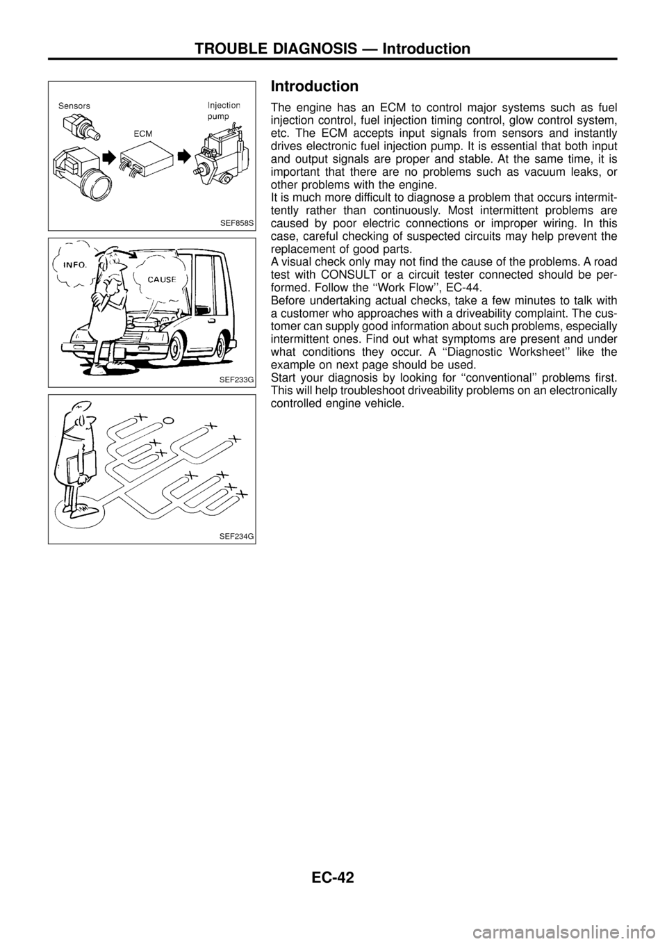
The engine has an ECM to control major systems such as fuel
injection control, fuel injection timing control, glow control system,
etc. The ECM accepts input signals from sensors and instantly
drives electronic fuel injection pump. It is essential that both input
and output signals are proper and stable. At the same time, it is
important that there are no problems such as vacuum leaks, or
other problems with the engine.
It is much more difficult to diagnose a problem that occurs intermit-
tently rather than continuously. Most intermittent problems are
caused by poor electric connections or improper wiring. In this
case, careful checking of suspected circuits may help prevent the
replacement of good parts.
A visual check only may not ®nd the cause of the problems. A road
test with CONSULT or a circuit tester connected should be per-
formed. Follow the ``Work Flow'', EC-44.
Before undertaking actual checks, take a few minutes to talk with
a customer who approaches with a driveability complaint. The cus-
tomer can supply good information about such problems, especially
intermittent ones. Find out what symptoms are present and under
what conditions they occur. A ``Diagnostic Worksheet'' like the
example on next page should be used.
Start your diagnosis by looking for ``conventional'' problems ®rst.
This will help troubleshoot driveability problems on an electronically
controlled engine vehicle.
SEF858S
SEF233G
SEF234G
TROUBLE DIAGNOSIS Ð Introduction
EC-42