engine NISSAN PATROL 1998 Y61 / 5.G Engine Control Repair Manual
[x] Cancel search | Manufacturer: NISSAN, Model Year: 1998, Model line: PATROL, Model: NISSAN PATROL 1998 Y61 / 5.GPages: 192, PDF Size: 4.28 MB
Page 84 of 192
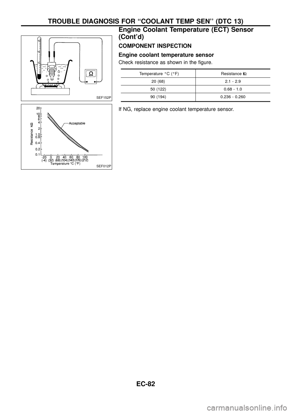
COMPONENT INSPECTION
Engine coolant temperature sensor
Check resistance as shown in the ®gure.
Temperature ÉC (ÉF) Resistance kW
20 (68) 2.1 - 2.9
50 (122) 0.68 - 1.0
90 (194) 0.236 - 0.260
If NG, replace engine coolant temperature sensor.
SEF152P
SEF012P
TROUBLE DIAGNOSIS FOR ``COOLANT TEMP SEN'' (DTC 13)
Engine Coolant Temperature (ECT) Sensor
(Cont'd)
EC-82
Page 85 of 192
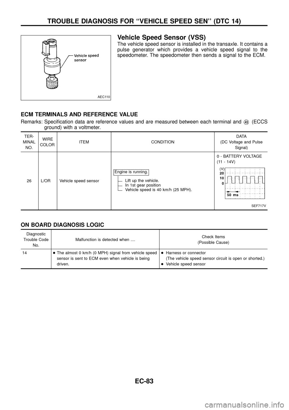
Vehicle Speed Sensor (VSS)
The vehicle speed sensor is installed in the transaxle. It contains a
pulse generator which provides a vehicle speed signal to the
speedometer. The speedometer then sends a signal to the ECM.
ECM TERMINALS AND REFERENCE VALUE
Remarks: Speci®cation data are reference values and are measured between each terminal andV43(ECCS
ground) with a voltmeter.
TER-
MINAL
NO.WIRE
COLORITEM CONDITIONDATA
(DC Voltage and Pulse
Signal)
26 L/OR Vehicle speed sensorEngine is running.
Lift up the vehicle.In 1st gear positionVehicle speed is 40 km/h (25 MPH).0 - BATTERY VOLTAGE
(11 - 14V)
SEF717V
ON BOARD DIAGNOSIS LOGIC
Diagnostic
Trouble Code
No.Malfunction is detected when ....Check Items
(Possible Cause)
14+The almost 0 km/h (0 MPH) signal from vehicle speed
sensor is sent to ECM even when vehicle is being
driven.+Harness or connector
(The vehicle speed sensor circuit is open or shorted.)
+Vehicle speed sensor
AEC110
TROUBLE DIAGNOSIS FOR ``VEHICLE SPEED SEN'' (DTC 14)
EC-83
Page 86 of 192
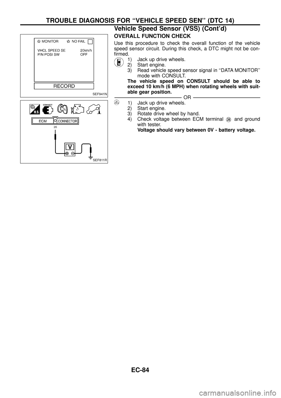
OVERALL FUNCTION CHECK
Use this procedure to check the overall function of the vehicle
speed sensor circuit. During this check, a DTC might not be con-
®rmed.
1) Jack up drive wheels.
2) Start engine.
3) Read vehicle speed sensor signal in ``DATA MONITOR''
mode with CONSULT.
The vehicle speed on CONSULT should be able to
exceed 10 km/h (6 MPH) when rotating wheels with suit-
able gear position.
-------------------------------------------------------------------------------------------------------------------------------------------------------------------------------------------------------------------------------------------------------OR-------------------------------------------------------------------------------------------------------------------------------------------------------------------------------------------------------------------------------------------------------
1) Jack up drive wheels.
2) Start engine.
3) Rotate drive wheel by hand.
4) Check voltage between ECM terminal
V26and ground
with tester.
Voltage should vary between 0V - battery voltage.
SEF941N
SEF811R
TROUBLE DIAGNOSIS FOR ``VEHICLE SPEED SEN'' (DTC 14)
Vehicle Speed Sensor (VSS) (Cont'd)
EC-84
Page 89 of 192
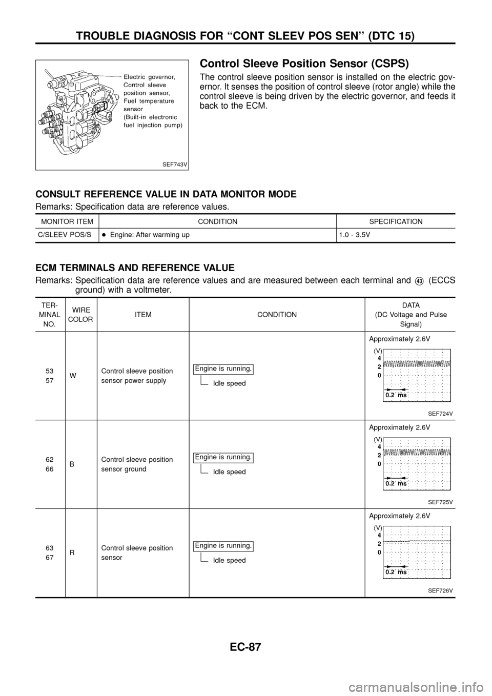
Control Sleeve Position Sensor (CSPS)
The control sleeve position sensor is installed on the electric gov-
ernor. It senses the position of control sleeve (rotor angle) while the
control sleeve is being driven by the electric governor, and feeds it
back to the ECM.
CONSULT REFERENCE VALUE IN DATA MONITOR MODE
Remarks: Speci®cation data are reference values.
MONITOR ITEM CONDITION SPECIFICATION
C/SLEEV POS/S+Engine: After warming up 1.0 - 3.5V
ECM TERMINALS AND REFERENCE VALUE
Remarks: Speci®cation data are reference values and are measured between each terminal andV43(ECCS
ground) with a voltmeter.
TER-
MINAL
NO.WIRE
COLORITEM CONDITIONDATA
(DC Voltage and Pulse
Signal)
53
57WControl sleeve position
sensor power supplyEngine is running.
Idle speedApproximately 2.6V
SEF724V
62
66BControl sleeve position
sensor groundEngine is running.
Idle speedApproximately 2.6V
SEF725V
63
67RControl sleeve position
sensorEngine is running.
Idle speedApproximately 2.6V
SEF726V
SEF743V
TROUBLE DIAGNOSIS FOR ``CONT SLEEV POS SEN'' (DTC 15)
EC-87
Page 90 of 192

ON BOARD DIAGNOSIS LOGIC
Diagnostic
Trouble Code
No.Malfunction is detected when ....Check Items
(Possible cause)
15+An excessively high or low voltage from the sensor is
detected by ECM.
...........................................................................................
+An improper voltage signal from the sensor is
detected by ECM during engine running.+Harness or connectors
(The control sleeve position sensor circuit is open or
shorted.)
+Control sleeve position sensor
DIAGNOSTIC TROUBLE CODE CONFIRMATION
PROCEDURE
1) Turn ignition switch ``ON'' and select ``DATA MONITOR''
mode with CONSULT.
2) Start engine and run it for at least 2 seconds at idle
speed.
-------------------------------------------------------------------------------------------------------------------------------------------------------------------------------------------------------------------------------------------------------OR-------------------------------------------------------------------------------------------------------------------------------------------------------------------------------------------------------------------------------------------------------
1) Start engine and run it for at least 2 seconds at idle
speed.
2) Turn ignition switch ``OFF'', wait at least 5 seconds and
then ``ON''.
3) Perform ``Diagnostic Test Mode II (Self-diagnostic
results)'' with ECM.
SEF714V
TROUBLE DIAGNOSIS FOR ``CONT SLEEV POS SEN'' (DTC 15)
Control Sleeve Position Sensor (CSPS) (Cont'd)
EC-88
Page 92 of 192

DIAGNOSTIC PROCEDURE
INSPECTION START
CHECK POWER SUPPLY CIRCUIT.
1. Turn ignition switch ``OFF''.
2. Disconnect ECM harness connector
and electronic fuel injection pump har-
ness connector.
3. Check harness continuity between ter-
minal
V2and ECM terminalsV53,V57.
Continuity should exist.
If OK, check harness for short to
ground and short to power.
OK
cNG
Repair open circuit or short
to ground or short to power
in harness or connectors.
CHECK INPUT SIGNAL CIRCUIT.
Check harness continuity between sensor
terminal
V3and ECM terminalsV63,V67.
Continuity should exist.
If OK, check harness for short to ground
and short to power.
OK
cNG
Repair open circuit or short
to ground or short to power
in harness or connectors.
CHECK GROUND CIRCUIT-I.
Check harness continuity between sensor
terminal
V6and ECM terminalsV62,V66.
Continuity should exist.
If OK, check harness for short to ground
and short to power.
OK
cNG
Repair open circuit or short
to ground or short to power
in harness or connectors.
CHECK GROUND CIRCUIT-II.
1. Loosen and retighten engine ground
screws.
2. Check harness continuity between ter-
minal
V4and engine ground.
Continuity should exist.
If OK, check harness for short to
ground and short to power.
OK
cNG
Check the following.
+Joint connector
F19
+Harness for open or
short between control
sleeve position sensor
and engine ground
If NG, repair open circuit or
short to ground or short to
power in harness or con-
nectors.
jA
SEF679V
SEF744V
SEF745V
SEF746V
SEF676V
.
.
.
.
.
TROUBLE DIAGNOSIS FOR ``CONT SLEEV POS SEN'' (DTC 15)
Control Sleeve Position Sensor (CSPS) (Cont'd)
EC-90
Page 94 of 192

Adjustment Resistor
The adjustment resistor is used to achieve uniform pump charac-
teristics.
ECM TERMINALS AND REFERENCE VALUE
Remarks: Speci®cation data are reference values and are measured between each terminal andV43(ECCS
ground) with a voltmeter.
TER-
MINAL
NO.WIRE
COLORITEM CONDITIONDATA
(DC Voltage and Pulse
Signal)
46 Y Adjustment resistor Ignition switch ``ON''
Approximately 0 - 4.6V
(Voltage varies with part
number of adjustment
resistor.)
50 B Sensors' groundEngine is running.
(Warm-up condition)
Idle speedApproximately 0V
ON BOARD DIAGNOSIS LOGIC
Diagnostic
Trouble Code
No.Malfunction is detected when ...Check Items
(Possible Cause)
17+An excessively high or low voltage from the resistor is
detected by ECM.+Harness or connectors
(The adjustment resistor circuit is open or shorted.)
+Adjustment resistor
DIAGNOSTIC TROUBLE CODE CONFIRMATION
PROCEDURE
1) Turn ignition switch ``ON''.
2) Select ``DATA MONITOR'' mode with CONSULT.
3) Wait at least 5 seconds.
-------------------------------------------------------------------------------------------------------------------------------------------------------------------------------------------------------------------------------------------------------OR-------------------------------------------------------------------------------------------------------------------------------------------------------------------------------------------------------------------------------------------------------
1) Turn ignition switch ``ON'' and wait at least 5 seconds.
2) Turn ignition switch ``OFF'', wait at least 5 seconds and
then turn ``ON''.
3) Perform ``Diagnostic Test Mode II (Self-diagnostic
results)'' with ECM.
SEF681V
SEF748V
TROUBLE DIAGNOSIS FOR ``ADJUST RESISTOR'' (DTC 17)
EC-92
Page 96 of 192

DIAGNOSTIC PROCEDURE
INSPECTION START
CHECK POWER SUPPLY.
1. Turn ignition switch ``OFF''.
2. Disconnect electronic fuel injection
pump harness connector.
3. Turn ignition switch ``ON''.
4. Check voltage between terminal
V2
and ground.
Voltage:
Approximately 5V
OK
cNG
Repair harness or connec-
tors.
CHECK GROUND CIRCUIT.
1. Turn ignition switch ``OFF''.
2. Check harness continuity between ter-
minal
V6and engine ground.
Continuity should exist.
If OK, check harness for short to
ground and short to power.
OK
cNG
Check the following.
+Harness connectors
F6,M51
+Harness connectors
M88,E106
+Harness for open or
short between ECM and
adjustment resistor
+Harness for open or
short between TCM and
adjustment resistor
If NG, repair open circuit or
short to ground or short to
power in harness or con-
nectors.
CHECK COMPONENT
(Adjustment resistor).
Refer to ``COMPONENT INSPECTION''
on next page.
OK
cNG
Replace adjustment resis-
tor.
Disconnect and reconnect harness con-
nectors in the circuit. Then retest.
Trouble is not ®xed.
Check ECM pin terminals for damage and
check the connection of ECM harness
connector.
Reconnect ECM harness connector and
retest.
INSPECTION END
SEF682V
SEF749V
SEF750V
.
.
.
.
.
.
TROUBLE DIAGNOSIS FOR ``ADJUST RESISTOR'' (DTC 17)
Adjustment Resistor (Cont'd)
EC-94
Page 98 of 192
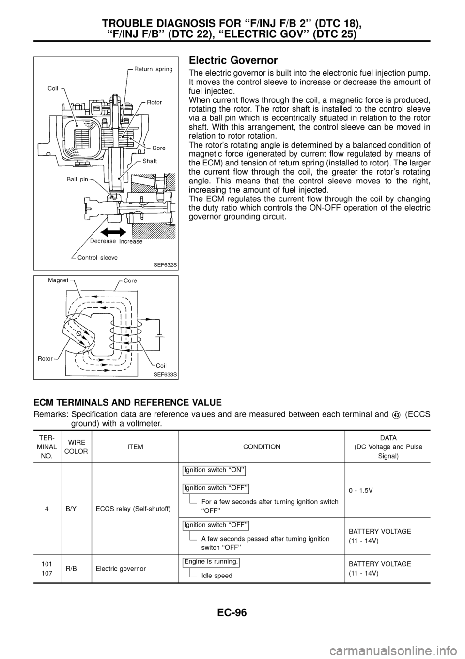
Electric Governor
The electric governor is built into the electronic fuel injection pump.
It moves the control sleeve to increase or decrease the amount of
fuel injected.
When current ¯ows through the coil, a magnetic force is produced,
rotating the rotor. The rotor shaft is installed to the control sleeve
via a ball pin which is eccentrically situated in relation to the rotor
shaft. With this arrangement, the control sleeve can be moved in
relation to rotor rotation.
The rotor's rotating angle is determined by a balanced condition of
magnetic force (generated by current ¯ow regulated by means of
the ECM) and tension of return spring (installed to rotor). The larger
the current ¯ow through the coil, the greater the rotor's rotating
angle. This means that the control sleeve moves to the right,
increasing the amount of fuel injected.
The ECM regulates the current ¯ow through the coil by changing
the duty ratio which controls the ON-OFF operation of the electric
governor grounding circuit.
ECM TERMINALS AND REFERENCE VALUE
Remarks: Speci®cation data are reference values and are measured between each terminal andV43(ECCS
ground) with a voltmeter.
TER-
MINAL
NO.WIRE
COLORITEM CONDITIONDATA
(DC Voltage and Pulse
Signal)
4 B/Y ECCS relay (Self-shutoff)Ignition switch ``ON''
Ignition switch ``OFF''
For a few seconds after turning ignition switch
``OFF''0 - 1.5V
Ignition switch ``OFF''
A few seconds passed after turning ignition
switch ``OFF''BATTERY VOLTAGE
(11 - 14V)
101
107R/B Electric governorEngine is running.
Idle speedBATTERY VOLTAGE
(11 - 14V)
SEF632S
SEF633S
TROUBLE DIAGNOSIS FOR ``F/INJ F/B 2'' (DTC 18),
``F/INJ F/B'' (DTC 22), ``ELECTRIC GOV'' (DTC 25)
EC-96
Page 99 of 192
TER-
MINAL
NO.WIRE
COLORITEM CONDITIONDATA
(DC Voltage and Pulse
Signal)
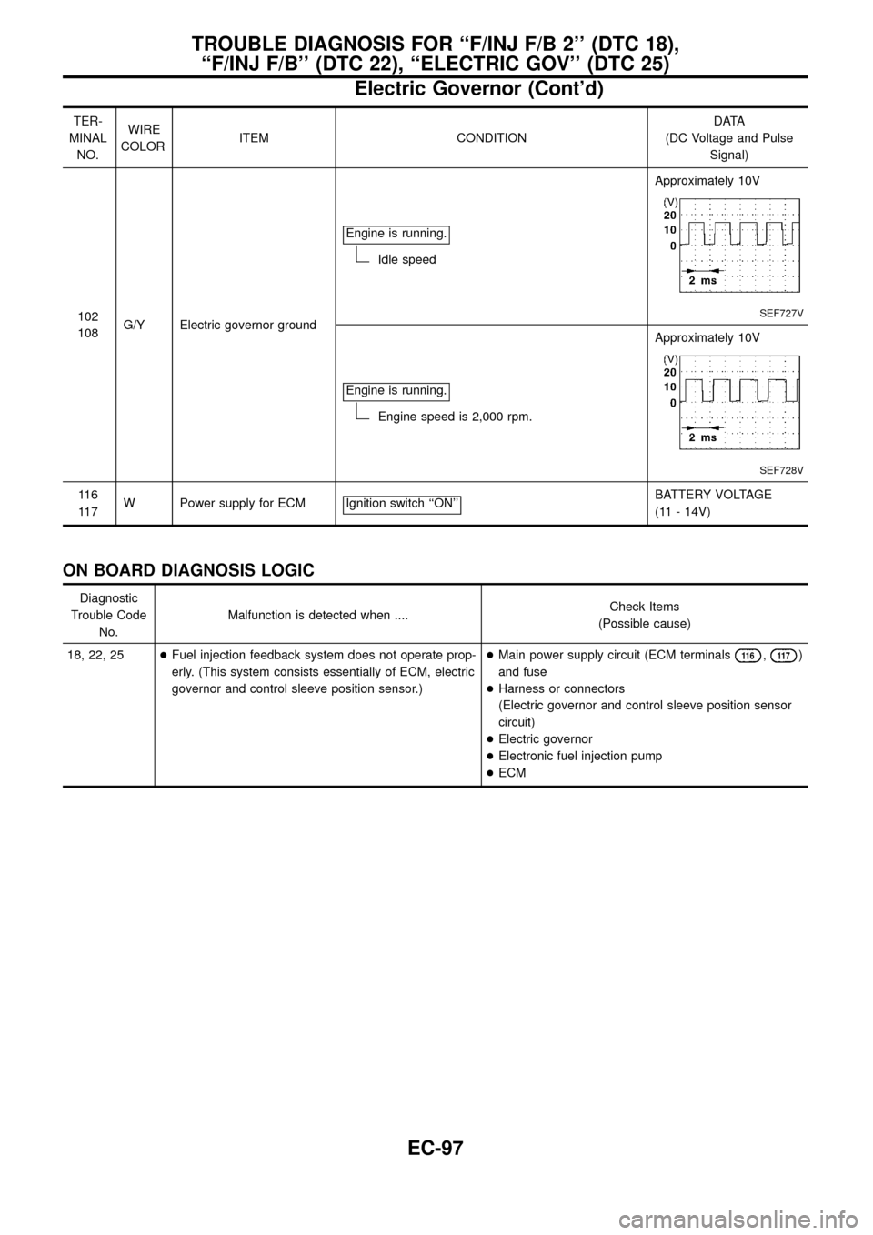
102
108G/Y Electric governor groundEngine is running.
Idle speedApproximately 10V
SEF727V
Engine is running.
Engine speed is 2,000 rpm.Approximately 10V
SEF728V
11 6
11 7W Power supply for ECM Ignition switch ``ON''BATTERY VOLTAGE
(11 - 14V)
ON BOARD DIAGNOSIS LOGIC
Diagnostic
Trouble Code
No.Malfunction is detected when ....Check Items
(Possible cause)
18, 22, 25+Fuel injection feedback system does not operate prop-
erly. (This system consists essentially of ECM, electric
governor and control sleeve position sensor.)+Main power supply circuit (ECM terminals
11 6,11 7)
and fuse
+Harness or connectors
(Electric governor and control sleeve position sensor
circuit)
+Electric governor
+Electronic fuel injection pump
+ECM
TROUBLE DIAGNOSIS FOR ``F/INJ F/B 2'' (DTC 18),
``F/INJ F/B'' (DTC 22), ``ELECTRIC GOV'' (DTC 25)
Electric Governor (Cont'd)
EC-97