NISSAN PATROL 1998 Y61 / 5.G Propeller Shaft And Differential Carrier User Guide
PATROL 1998 Y61 / 5.G
NISSAN
NISSAN
https://www.carmanualsonline.info/img/5/625/w960_625-0.png
NISSAN PATROL 1998 Y61 / 5.G Propeller Shaft And Differential Carrier User Guide
Trending: sensor, engine, Front bearing, oil, steering, transmission oil, check oil
Page 11 of 54
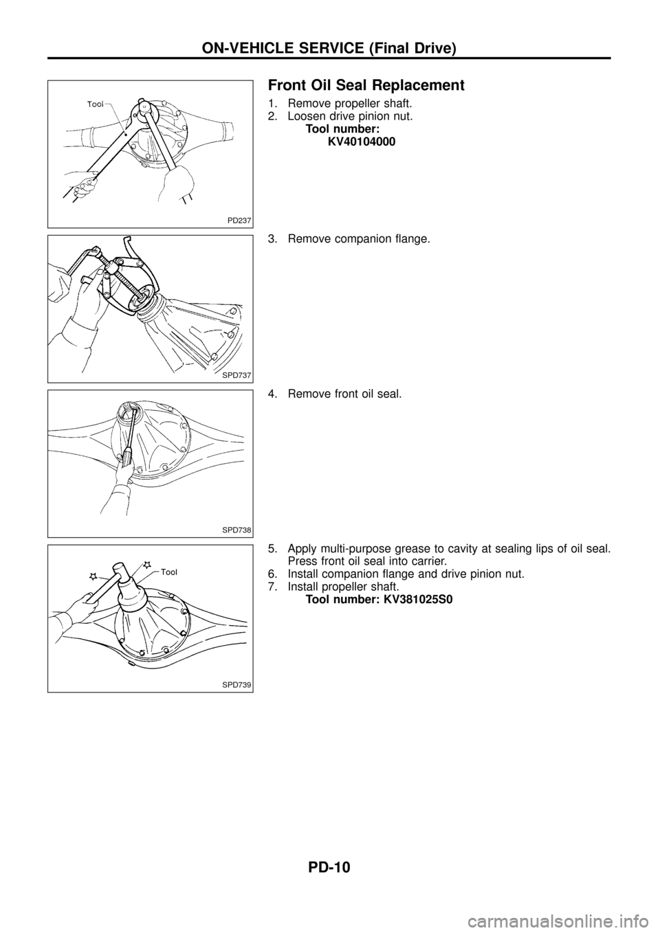
Front Oil Seal Replacement
1. Remove propeller shaft.
2. Loosen drive pinion nut.
Tool number:
KV40104000
3. Remove companion ¯ange.
4. Remove front oil seal.
5. Apply multi-purpose grease to cavity at sealing lips of oil seal.
Press front oil seal into carrier.
6. Install companion ¯ange and drive pinion nut.
7. Install propeller shaft.
Tool number: KV381025S0
PD237
SPD737
SPD738
SPD739
ON-VEHICLE SERVICE (Final Drive)
PD-10
Page 12 of 54
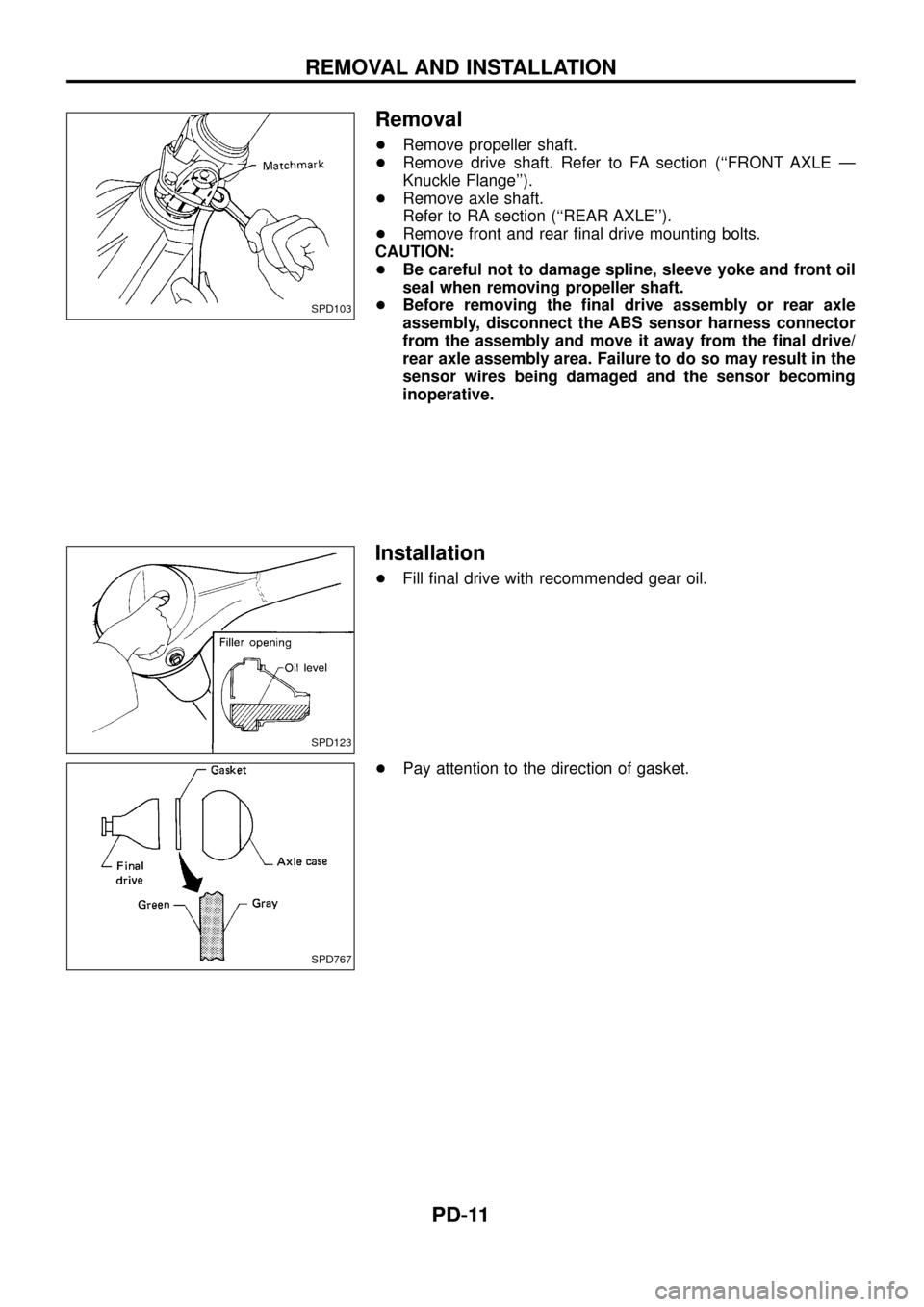
Removal
+Remove propeller shaft.
+Remove drive shaft. Refer to FA section (``FRONT AXLE Ð
Knuckle Flange'').
+Remove axle shaft.
Refer to RA section (``REAR AXLE'').
+Remove front and rear ®nal drive mounting bolts.
CAUTION:
+Be careful not to damage spline, sleeve yoke and front oil
seal when removing propeller shaft.
+Before removing the ®nal drive assembly or rear axle
assembly, disconnect the ABS sensor harness connector
from the assembly and move it away from the ®nal drive/
rear axle assembly area. Failure to do so may result in the
sensor wires being damaged and the sensor becoming
inoperative.
Installation
+Fill ®nal drive with recommended gear oil.
+Pay attention to the direction of gasket.
SPD103
SPD123
SPD767
REMOVAL AND INSTALLATION
PD-11
Page 13 of 54
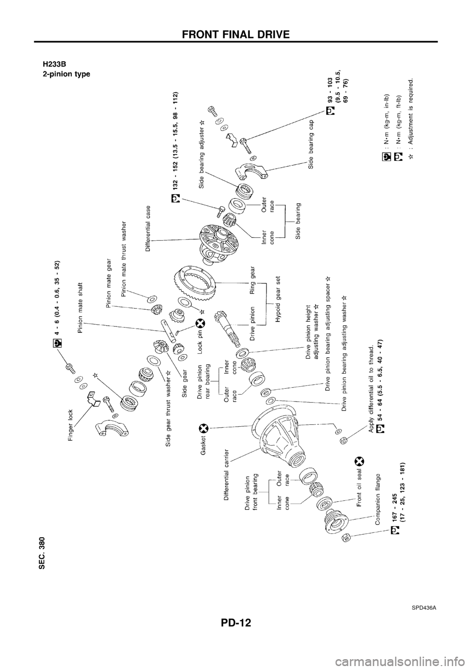
SPD436A
FRONT FINAL DRIVE
PD-12
Page 14 of 54
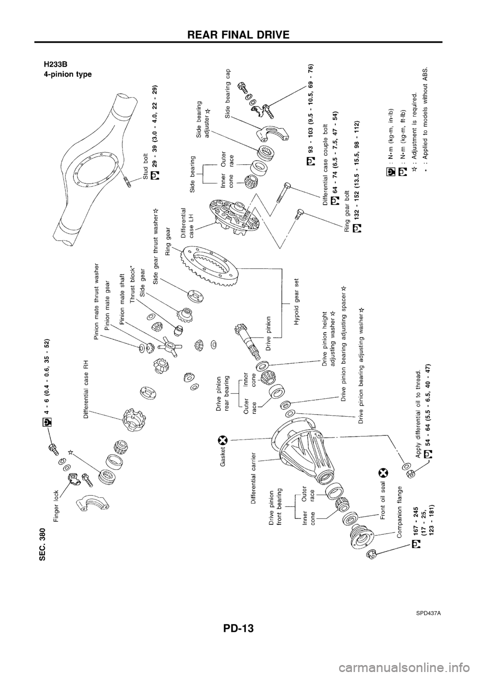
SPD437A
REAR FINAL DRIVE
PD-13
Page 15 of 54
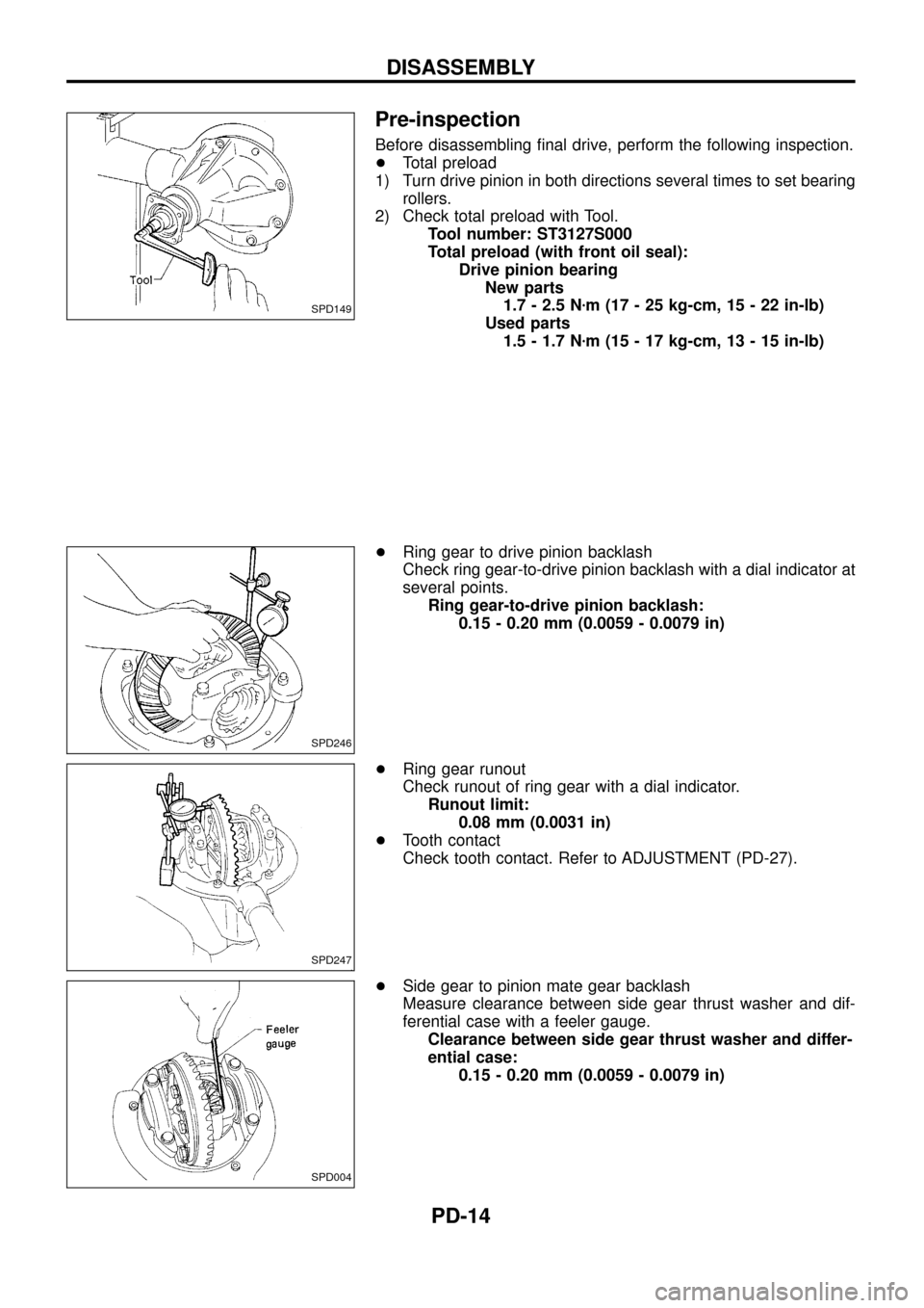
Pre-inspection
Before disassembling ®nal drive, perform the following inspection.
+Total preload
1) Turn drive pinion in both directions several times to set bearing
rollers.
2) Check total preload with Tool.
Tool number: ST3127S000
Total preload (with front oil seal):
Drive pinion bearing
New parts
1.7 - 2.5 Nzm (17 - 25 kg-cm, 15 - 22 in-lb)
Used parts
1.5 - 1.7 Nzm (15 - 17 kg-cm, 13 - 15 in-lb)
+Ring gear to drive pinion backlash
Check ring gear-to-drive pinion backlash with a dial indicator at
several points.
Ring gear-to-drive pinion backlash:
0.15 - 0.20 mm (0.0059 - 0.0079 in)
+Ring gear runout
Check runout of ring gear with a dial indicator.
Runout limit:
0.08 mm (0.0031 in)
+Tooth contact
Check tooth contact. Refer to ADJUSTMENT (PD-27).
+Side gear to pinion mate gear backlash
Measure clearance between side gear thrust washer and dif-
ferential case with a feeler gauge.
Clearance between side gear thrust washer and differ-
ential case:
0.15 - 0.20 mm (0.0059 - 0.0079 in)
SPD149
SPD246
SPD247
SPD004
DISASSEMBLY
PD-14
Page 16 of 54
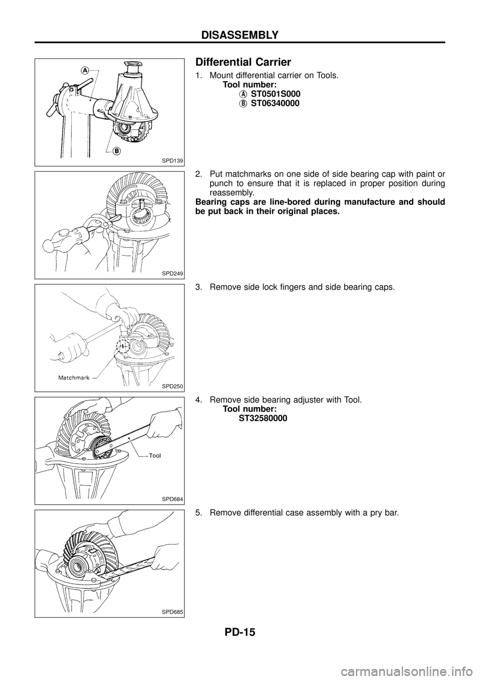
Differential Carrier
1. Mount differential carrier on Tools.
Tool number:
j
AST0501S000
j
BST06340000
2. Put matchmarks on one side of side bearing cap with paint or
punch to ensure that it is replaced in proper position during
reassembly.
Bearing caps are line-bored during manufacture and should
be put back in their original places.
3. Remove side lock ®ngers and side bearing caps.
4. Remove side bearing adjuster with Tool.
Tool number:
ST32580000
5. Remove differential case assembly with a pry bar.
SPD139
SPD249
SPD250
SPD684
SPD685
DISASSEMBLY
PD-15
Page 17 of 54
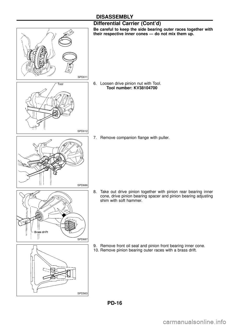
Be careful to keep the side bearing outer races together with
their respective inner cones Ð do not mix them up.
6. Loosen drive pinion nut with Tool.
Tool number: KV38104700
7. Remove companion ¯ange with puller.
8. Take out drive pinion together with pinion rear bearing inner
cone, drive pinion bearing spacer and pinion bearing adjusting
shim with soft hammer.
9. Remove front oil seal and pinion front bearing inner cone.
10. Remove pinion bearing outer races with a brass drift.
SPD011
SPD012
SPD686
SPD687
SPD563
DISASSEMBLY
Differential Carrier (Cont'd)
PD-16
Page 18 of 54
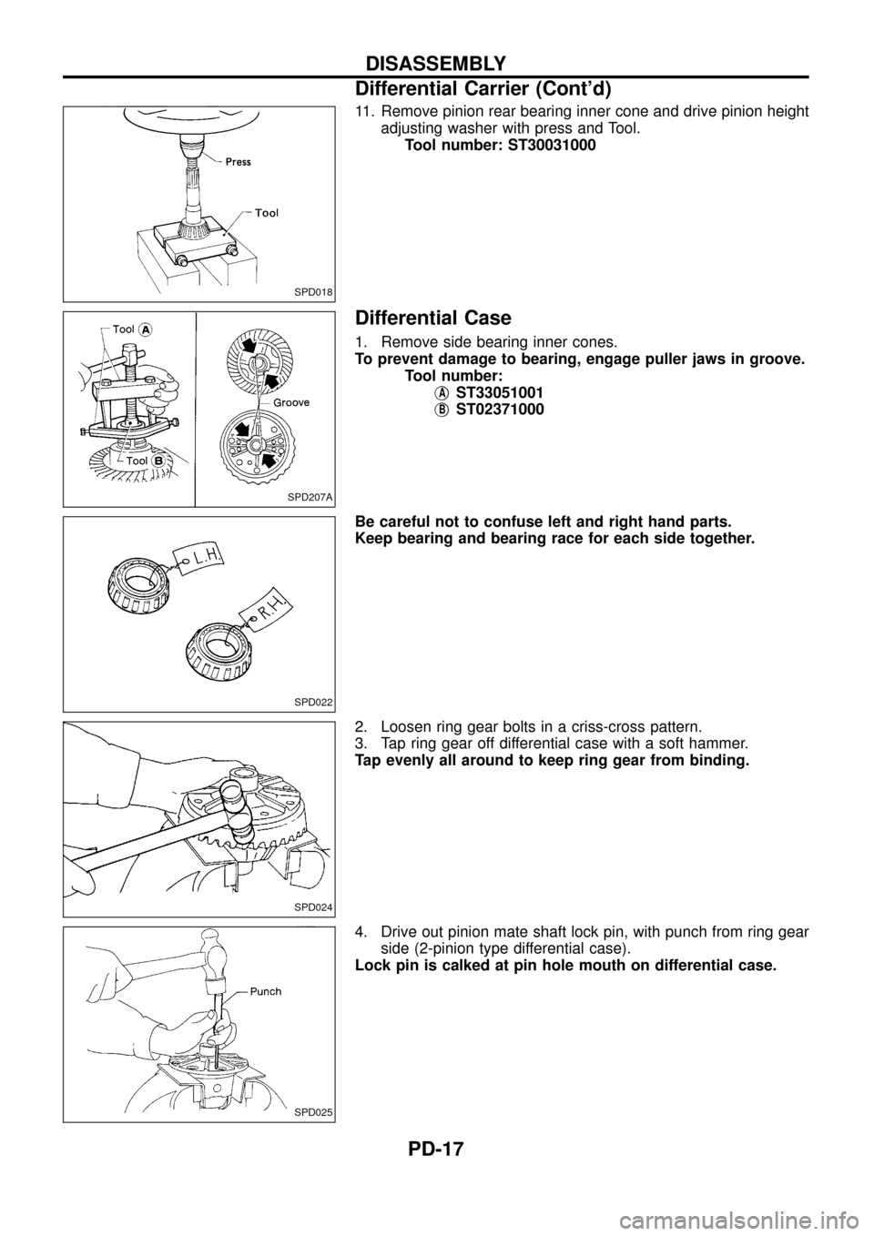
11. Remove pinion rear bearing inner cone and drive pinion height
adjusting washer with press and Tool.
Tool number: ST30031000
Differential Case
1. Remove side bearing inner cones.
To prevent damage to bearing, engage puller jaws in groove.
Tool number:
j
AST33051001
j
BST02371000
Be careful not to confuse left and right hand parts.
Keep bearing and bearing race for each side together.
2. Loosen ring gear bolts in a criss-cross pattern.
3. Tap ring gear off differential case with a soft hammer.
Tap evenly all around to keep ring gear from binding.
4. Drive out pinion mate shaft lock pin, with punch from ring gear
side (2-pinion type differential case).
Lock pin is calked at pin hole mouth on differential case.
SPD018
SPD207A
SPD022
SPD024
SPD025
DISASSEMBLY
Differential Carrier (Cont'd)
PD-17
Page 19 of 54
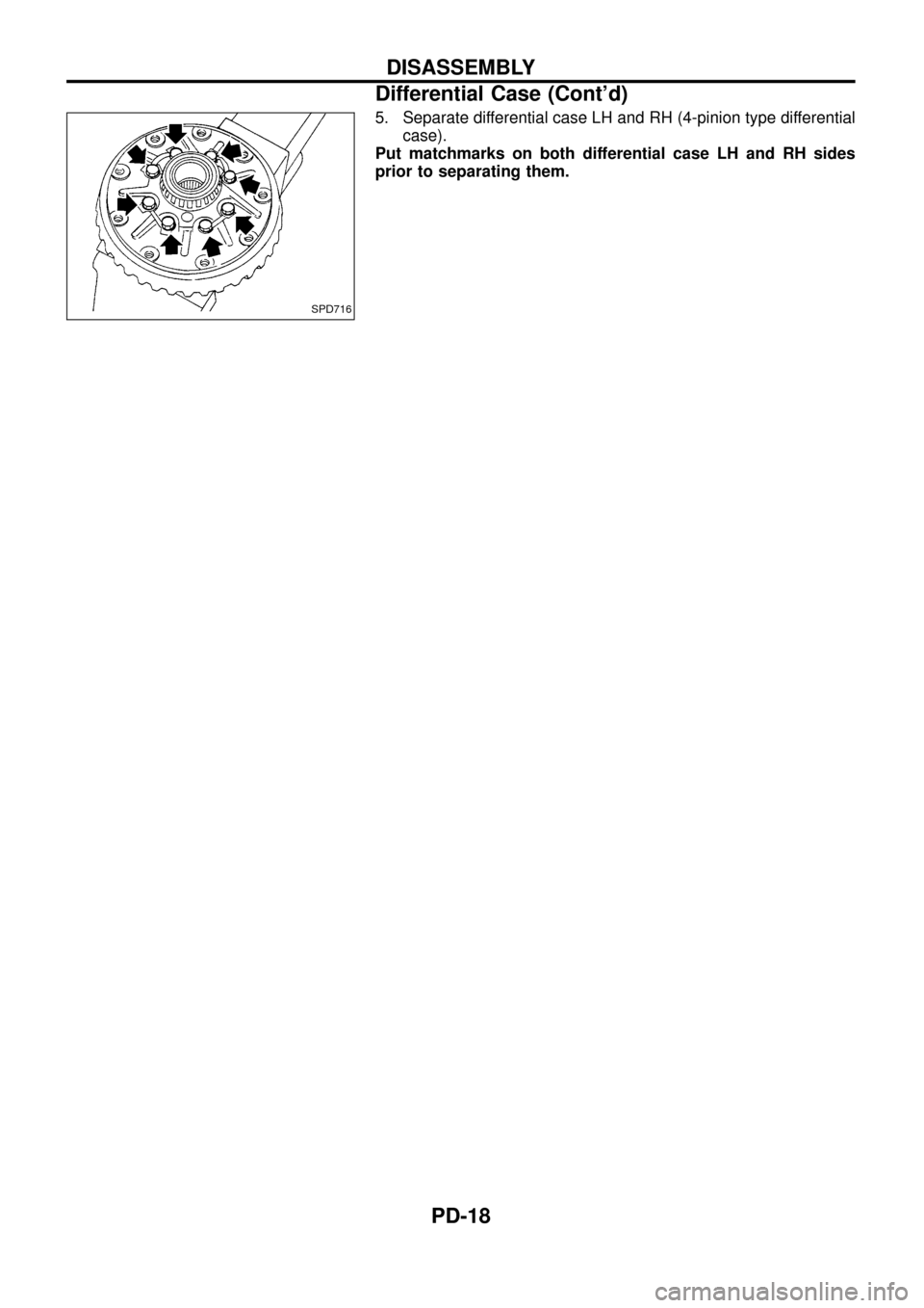
5. Separate differential case LH and RH (4-pinion type differential
case).
Put matchmarks on both differential case LH and RH sides
prior to separating them.
SPD716
DISASSEMBLY
Differential Case (Cont'd)
PD-18
Page 20 of 54
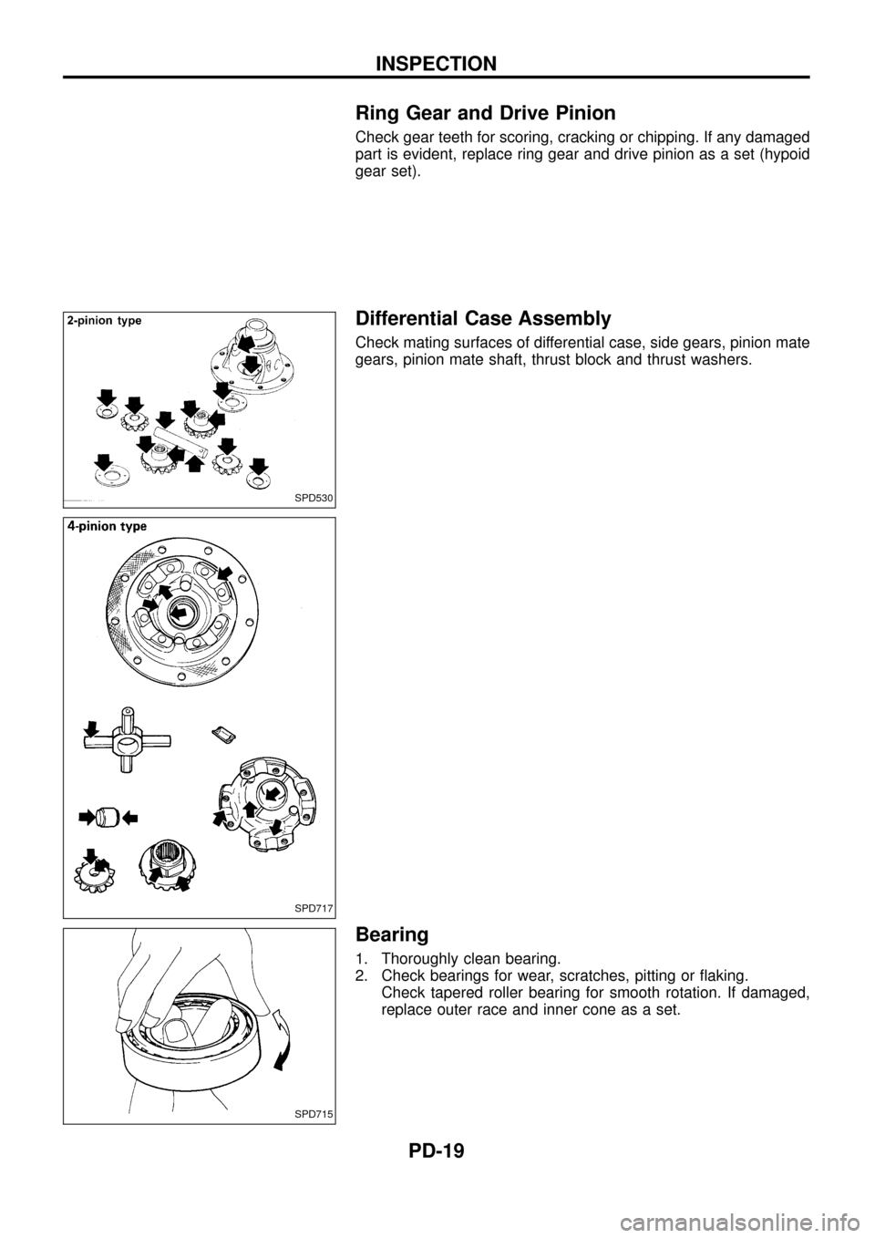
Ring Gear and Drive Pinion
Check gear teeth for scoring, cracking or chipping. If any damaged
part is evident, replace ring gear and drive pinion as a set (hypoid
gear set).
Differential Case Assembly
Check mating surfaces of differential case, side gears, pinion mate
gears, pinion mate shaft, thrust block and thrust washers.
Bearing
1. Thoroughly clean bearing.
2. Check bearings for wear, scratches, pitting or ¯aking.
Check tapered roller bearing for smooth rotation. If damaged,
replace outer race and inner cone as a set.
SPD530
SPD717
SPD715
INSPECTION
PD-19
Trending: steering wheel, engine, oil level, bolt pattern, ESP, transmission, lock
