height adjustment NISSAN PATROL 1998 Y61 / 5.G Propeller Shaft And Differential Carrier Workshop Manual
[x] Cancel search | Manufacturer: NISSAN, Model Year: 1998, Model line: PATROL, Model: NISSAN PATROL 1998 Y61 / 5.GPages: 54, PDF Size: 1.85 MB
Page 1 of 54

PROPELLER SHAFT &
DIFFERENTIAL CARRIER
SECTION
PD
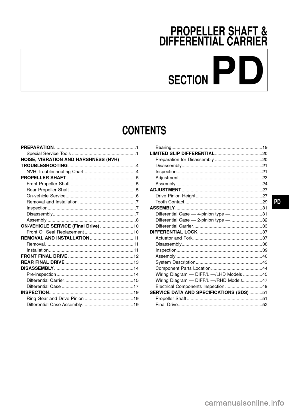
CONTENTS
PREPARATION................................................................1
Special Service Tools ..................................................1
NOISE, VIBRATION AND HARSHNESS (NVH)
TROUBLESHOOTING.....................................................4
NVH Troubleshooting Chart.........................................4
PROPELLER SHAFT......................................................5
Front Propeller Shaft ...................................................5
Rear Propeller Shaft ....................................................5
On-vehicle Service.......................................................6
Removal and Installation .............................................7
Inspection.....................................................................7
Disassembly.................................................................7
Assembly .....................................................................8
ON-VEHICLE SERVICE (Final Drive)..........................10
Front Oil Seal Replacement ......................................10
REMOVAL AND INSTALLATION.................................. 11
Removal ..................................................................... 11
Installation .................................................................. 11
FRONT FINAL DRIVE...................................................12
REAR FINAL DRIVE.....................................................13
DISASSEMBLY..............................................................14
Pre-inspection ............................................................14
Differential Carrier......................................................15
Differential Case ........................................................17
INSPECTION..................................................................19
Ring Gear and Drive Pinion ......................................19
Differential Case Assembly........................................19Bearing.......................................................................19
LIMITED SLIP DIFFERENTIAL.....................................20
Preparation for Disassembly .....................................20
Disassembly...............................................................21
Inspection...................................................................21
Adjustment .................................................................23
Assembly ...................................................................24
ADJUSTMENT...............................................................27
Drive Pinion Height ....................................................27
Tooth Contact.............................................................29
ASSEMBLY....................................................................31
Differential Case Ð 4-pinion type Ð.........................31
Differential Case Ð 2-pinion type Ð.........................32
Differential Carrier......................................................33
DIFFERENTIAL LOCK..................................................37
Actuator and Fork ......................................................37
Disassembly...............................................................38
Inspection...................................................................39
Assembly ...................................................................40
System Description ....................................................43
Component Parts Location ........................................44
Wiring Diagram Ð DIFF/L Ð/LHD Models ...............45
Wiring Diagram Ð DIFF/L Ð/RHD Models ...............47
Electrical Components Inspection .............................49
SERVICE DATA AND SPECIFICATIONS (SDS)..........51
Propeller Shaft ...........................................................51
Final Drive..................................................................52
PD
Page 28 of 54

To avoid confusion while calculating bearing shims, it is absolutely
necessary to stay with the metric system. If you measure anything
in inches,the results must be converted to the metric system.
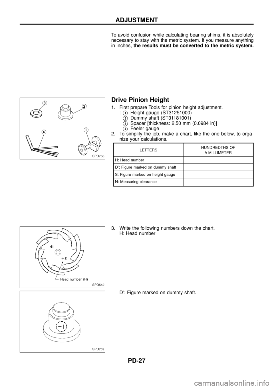
Drive Pinion Height
1. First prepare Tools for pinion height adjustment.
:
V1Height gauge (ST31251000)
V2Dummy shaft (ST31181001)
V3Spacer [thickness: 2.50 mm (0.0984 in)]
V4Feeler gauge
2. To simplify the job, make a chart, like the one below, to orga-
nize your calculations.
LETTERSHUNDREDTHS OF
A MILLIMETER
H: Head number
D¢: Figure marked on dummy shaft
S: Figure marked on height gauge
N: Measuring clearance
3. Write the following numbers down the chart.
H: Head number
D¢: Figure marked on dummy shaft.
SPD758
SPD542
SPD759
ADJUSTMENT
PD-27
Page 29 of 54

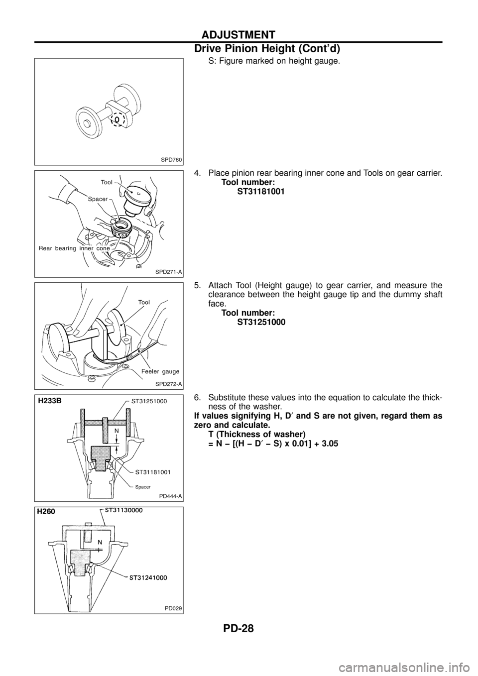
S: Figure marked on height gauge.
4. Place pinion rear bearing inner cone and Tools on gear carrier.
Tool number:
ST31181001
5. Attach Tool (Height gauge) to gear carrier, and measure the
clearance between the height gauge tip and the dummy shaft
face.
Tool number:
ST31251000
6. Substitute these values into the equation to calculate the thick-
ness of the washer.
If values signifying H, D¢and S are not given, regard them as
zero and calculate.
T (Thickness of washer)
=Nþ[(HþD¢þ S) x 0.01] + 3.05
SPD760
SPD271-A
SPD272-A
PD444-A
PD029
ADJUSTMENT
Drive Pinion Height (Cont'd)
PD-28
Page 30 of 54
![NISSAN PATROL 1998 Y61 / 5.G Propeller Shaft And Differential Carrier Workshop Manual Example (H233B):
N = 0.30
H=2
D¢=þ1
S=0
T=Nþ[(HþD¢þ S) x 0.01] + 3.05
= 0.30 þ [{2 þ (þ1) þ 0} x 0.01] + 3.05
(1) H ........................................................................ 2 NISSAN PATROL 1998 Y61 / 5.G Propeller Shaft And Differential Carrier Workshop Manual Example (H233B):
N = 0.30
H=2
D¢=þ1
S=0
T=Nþ[(HþD¢þ S) x 0.01] + 3.05
= 0.30 þ [{2 þ (þ1) þ 0} x 0.01] + 3.05
(1) H ........................................................................ 2](/img/5/625/w960_625-29.png)
Example (H233B):
N = 0.30
H=2
D¢=þ1
S=0
T=Nþ[(HþD¢þ S) x 0.01] + 3.05
= 0.30 þ [{2 þ (þ1) þ 0} x 0.01] + 3.05
(1) H ........................................................................ 2
þD¢................................................................. þ(þ1)
3
þS ...................................................................... þ0
3
(2) 3
x 0.01
0.03
(3) N ................................................................... 0.30
þ0.03
0.27
(4) 0.27
+3.05
3.32
\T = 3.32
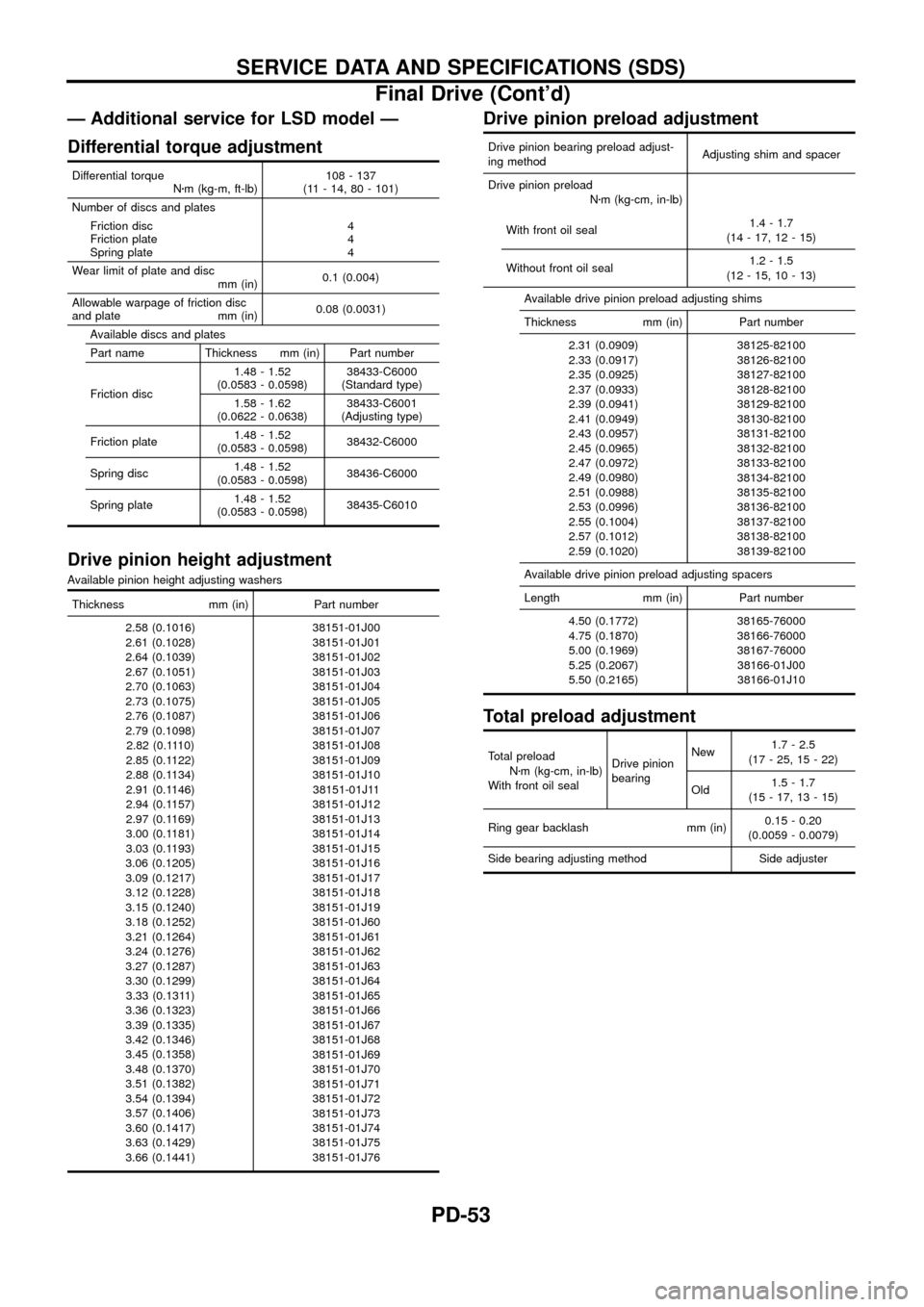
7. Select the proper pinion height washer.
Drive pinion height adjusting washer:
Refer to SDS (PD-0, 53).
If you cannot ®nd the desired thickness of washer, use washer
with thickness closest to the calculated value.
Example (H233B):
Calculated value ... T = 3.32 mm
Used washer ... T = 3.33 mm
Tooth Contact
Gear tooth contact pattern check is necessary to verify correct
relationship between ring gear and drive pinion.
Hypoid gear sets which are not positioned properly in relation to
one another may be noisy, or have short life or both. With a pat-
tern check, the most desirable contact for low noise level and long
life can be assured.
1. Thoroughly clean ring gear and drive pinion teeth.
2. Sparingly apply a mixture of powdered ferric oxide and oil or
equivalent to 3 or 4 teeth of ring gear drive side.
SPD005
ADJUSTMENT
Drive Pinion Height (Cont'd)
PD-29
Page 54 of 54

Ð Additional service for LSD model Ð
Differential torque adjustment
Differential torque
Nzm (kg-m, ft-lb)108 - 137
(11 - 14, 80 - 101)
Number of discs and plates
Friction disc
Friction plate
Spring plate4
4
4
Wear limit of plate and disc
mm (in)0.1 (0.004)
Allowable warpage of friction disc
and plate mm (in)0.08 (0.0031)
Available discs and plates
Part name Thickness mm (in) Part number
Friction disc1.48 - 1.52
(0.0583 - 0.0598)38433-C6000
(Standard type)
1.58 - 1.62
(0.0622 - 0.0638)38433-C6001
(Adjusting type)
Friction plate1.48 - 1.52
(0.0583 - 0.0598)38432-C6000
Spring disc1.48 - 1.52
(0.0583 - 0.0598)38436-C6000
Spring plate1.48 - 1.52
(0.0583 - 0.0598)38435-C6010
Drive pinion height adjustment
Available pinion height adjusting washers
Thickness mm (in) Part number
2.58 (0.1016)
2.61 (0.1028)
2.64 (0.1039)
2.67 (0.1051)
2.70 (0.1063)
2.73 (0.1075)
2.76 (0.1087)
2.79 (0.1098)
2.82 (0.1110)
2.85 (0.1122)
2.88 (0.1134)
2.91 (0.1146)
2.94 (0.1157)
2.97 (0.1169)
3.00 (0.1181)
3.03 (0.1193)
3.06 (0.1205)
3.09 (0.1217)
3.12 (0.1228)
3.15 (0.1240)
3.18 (0.1252)
3.21 (0.1264)
3.24 (0.1276)
3.27 (0.1287)
3.30 (0.1299)
3.33 (0.1311)
3.36 (0.1323)
3.39 (0.1335)
3.42 (0.1346)
3.45 (0.1358)
3.48 (0.1370)
3.51 (0.1382)
3.54 (0.1394)
3.57 (0.1406)
3.60 (0.1417)
3.63 (0.1429)
3.66 (0.1441)38151-01J00
38151-01J01
38151-01J02
38151-01J03
38151-01J04
38151-01J05
38151-01J06
38151-01J07
38151-01J08
38151-01J09
38151-01J10
38151-01J11
38151-01J12
38151-01J13
38151-01J14
38151-01J15
38151-01J16
38151-01J17
38151-01J18
38151-01J19
38151-01J60
38151-01J61
38151-01J62
38151-01J63
38151-01J64
38151-01J65
38151-01J66
38151-01J67
38151-01J68
38151-01J69
38151-01J70
38151-01J71
38151-01J72
38151-01J73
38151-01J74
38151-01J75
38151-01J76
Drive pinion preload adjustment
Drive pinion bearing preload adjust-
ing methodAdjusting shim and spacer
Drive pinion preload
Nzm (kg-cm, in-lb)
With front oil seal1.4 - 1.7
(14 - 17, 12 - 15)
Without front oil seal1.2 - 1.5
(12 - 15, 10 - 13)
Available drive pinion preload adjusting shims
Thickness mm (in) Part number
2.31 (0.0909)
2.33 (0.0917)
2.35 (0.0925)
2.37 (0.0933)
2.39 (0.0941)
2.41 (0.0949)
2.43 (0.0957)
2.45 (0.0965)
2.47 (0.0972)
2.49 (0.0980)
2.51 (0.0988)
2.53 (0.0996)
2.55 (0.1004)
2.57 (0.1012)
2.59 (0.1020)38125-82100
38126-82100
38127-82100
38128-82100
38129-82100
38130-82100
38131-82100
38132-82100
38133-82100
38134-82100
38135-82100
38136-82100
38137-82100
38138-82100
38139-82100
Available drive pinion preload adjusting spacers
Length mm (in) Part number
4.50 (0.1772)
4.75 (0.1870)
5.00 (0.1969)
5.25 (0.2067)
5.50 (0.2165)38165-76000
38166-76000
38167-76000
38166-01J00
38166-01J10
Total preload adjustment
Total preload
Nzm (kg-cm, in-lb)
With front oil sealDrive pinion
bearingNew1.7 - 2.5
(17 - 25, 15 - 22)
Old1.5 - 1.7
(15 - 17, 13 - 15)
Ring gear backlash mm (in)0.15 - 0.20
(0.0059 - 0.0079)
Side bearing adjusting method Side adjuster
SERVICE DATA AND SPECIFICATIONS (SDS)
Final Drive (Cont'd)
PD-53