NISSAN PATROL 2000 Electronic Repair Manual
Manufacturer: NISSAN, Model Year: 2000, Model line: PATROL, Model: NISSAN PATROL 2000Pages: 1033, PDF Size: 30.71 MB
Page 111 of 1033
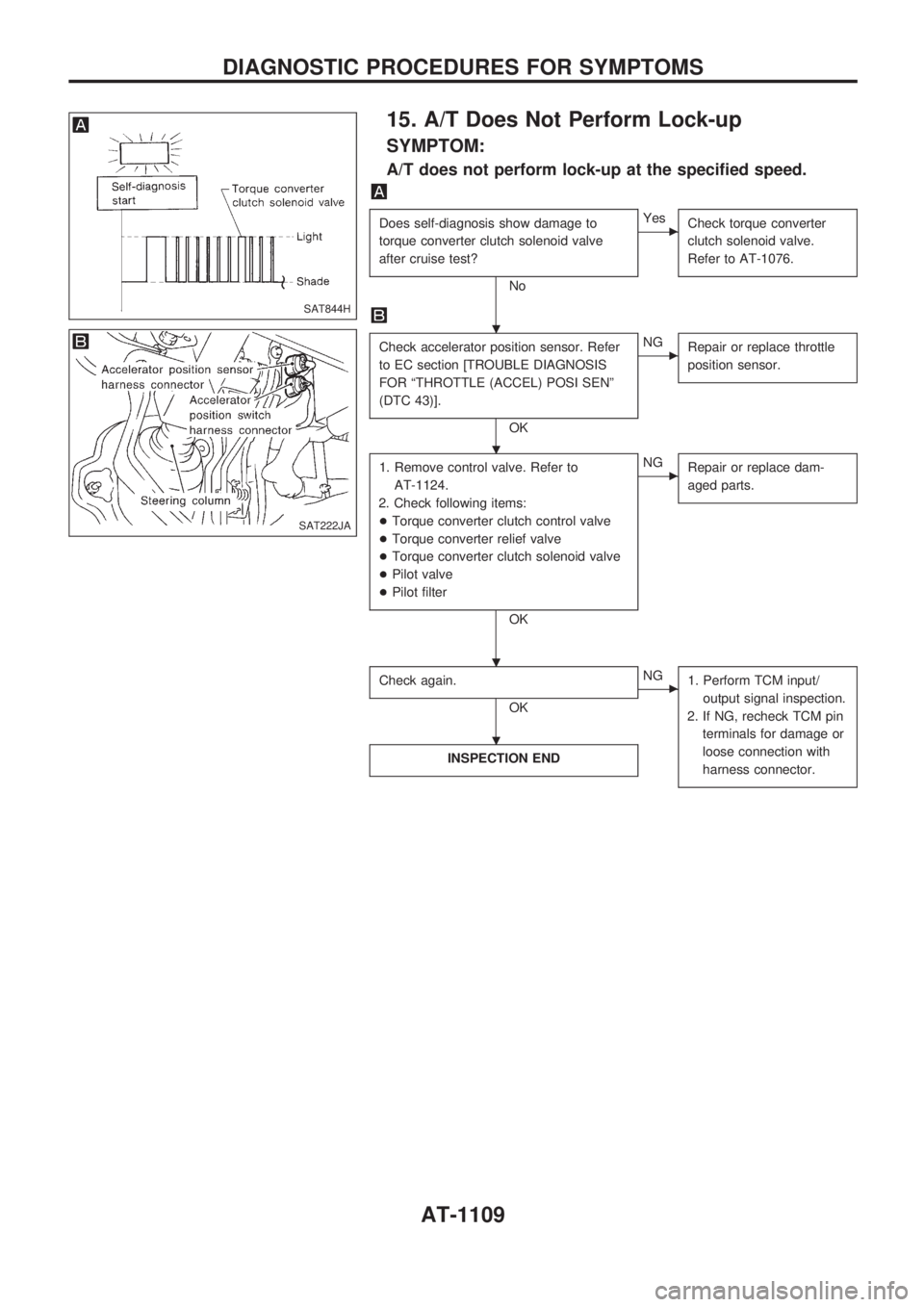
15. A/T Does Not Perform Lock-up
SYMPTOM:
A/T does not perform lock-up at the specified speed.
Does self-diagnosis show damage to
torque converter clutch solenoid valve
after cruise test?
No
cYes
Check torque converter
clutch solenoid valve.
Refer to AT-1076.
Check accelerator position sensor. Refer
to EC section [TROUBLE DIAGNOSIS
FOR ªTHROTTLE (ACCEL) POSI SENº
(DTC 43)].
OK
cNG
Repair or replace throttle
position sensor.
1. Remove control valve. Refer to
AT-1124.
2. Check following items:
+Torque converter clutch control valve
+Torque converter relief valve
+Torque converter clutch solenoid valve
+Pilot valve
+Pilot filter
OK
cNG
Repair or replace dam-
aged parts.
Check again.
OK
cNG
1. Perform TCM input/
output signal inspection.
2. If NG, recheck TCM pin
terminals for damage or
loose connection with
harness connector.
INSPECTION END
SAT844H
SAT222JA
.
.
. .
.
DIAGNOSTIC PROCEDURES FOR SYMPTOMS
AT-1109
Page 112 of 1033
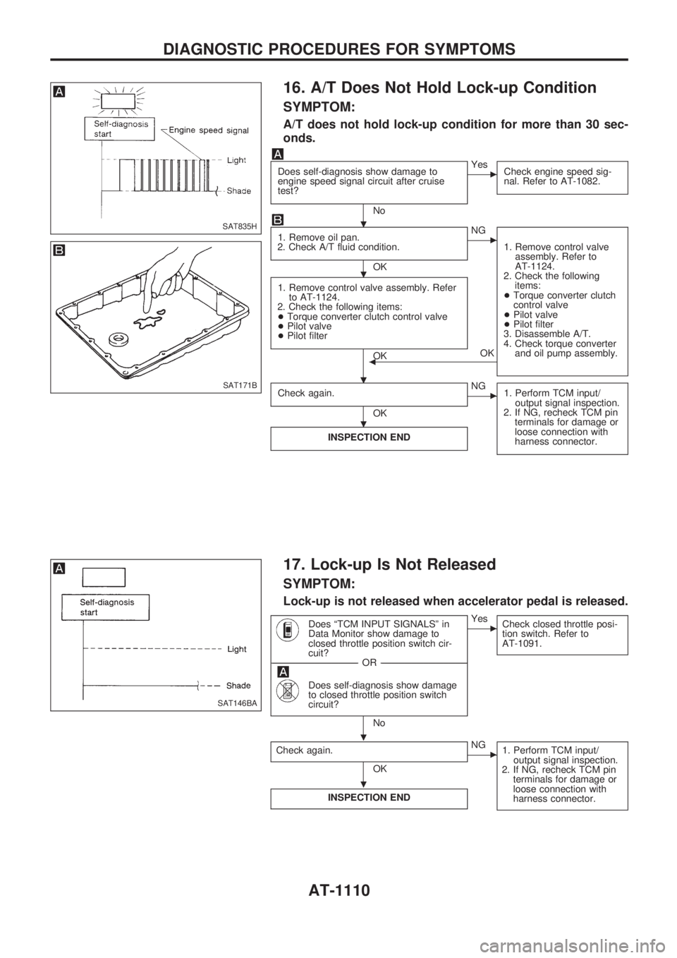
16. A/T Does Not Hold Lock-up Condition
SYMPTOM:
A/T does not hold lock-up condition for more than 30 sec-
onds.
Does self-diagnosis show damage to
engine speed signal circuit after cruise
test?
No
cYes
Check engine speed sig-
nal. Refer to AT-1082.
1. Remove oil pan.
2. Check A/T fluid condition.
OK
cNG
1. Remove control valve
assembly. Refer to
AT-1124.
2. Check the following
items:
+Torque converter clutch
control valve
+Pilot valve
+Pilot filter
3. Disassemble A/T.
4. Check torque converter
and oil pump assembly.
1. Remove control valve assembly. Refer
to AT-1124.
2. Check the following items:
+Torque converter clutch control valve
+Pilot valve
+Pilot filter
OKOKb
Check again.
OK
cNG
1. Perform TCM input/
output signal inspection.
2. If NG, recheck TCM pin
terminals for damage or
loose connection with
harness connector.
INSPECTION END
17. Lock-up Is Not Released
SYMPTOM:
Lock-up is not released when accelerator pedal is released.
Does ªTCM INPUT SIGNALSº in
Data Monitor show damage to
closed throttle position switch cir-
cuit?
------------------------------------------------------------------------------------------------------------------------------------OR------------------------------------------------------------------------------------------------------------------------------------
Does self-diagnosis show damage
to closed throttle position switch
circuit?
No
cYes
Check closed throttle posi-
tion switch. Refer to
AT-1091.
Check again.
OK
cNG
1. Perform TCM input/
output signal inspection.
2. If NG, recheck TCM pin
terminals for damage or
loose connection with
harness connector.
INSPECTION END
SAT835H
SAT171B
SAT146BA
.
.
. .
.
.
.
DIAGNOSTIC PROCEDURES FOR SYMPTOMS
AT-1110
Page 113 of 1033
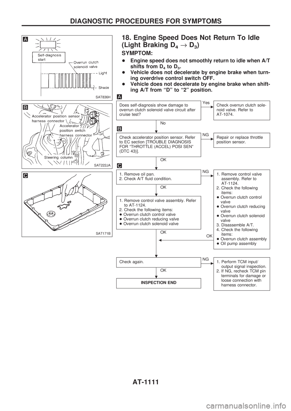
18. Engine Speed Does Not Return To Idle
(Light Braking D
4®D3)
SYMPTOM:
+Engine speed does not smoothly return to idle when A/T
shifts from D
4to D3.
+Vehicle does not decelerate by engine brake when turn-
ing overdrive control switch OFF.
+Vehicle does not decelerate by engine brake when shift-
ing A/T from ªDº to ª2º position.
Does self-diagnosis show damage to
overrun clutch solenoid valve circuit after
cruise test?
No
cYes
Check overrun clutch sole-
noid valve. Refer to
AT-1074.
Check accelerator position sensor. Refer
to EC section [TROUBLE DIAGNOSIS
FOR ªTHROTTLE (ACCEL) POSI SENº
(DTC 43)].
OK
cNG
Repair or replace throttle
position sensor.
1. Remove oil pan.
2. Check A/T fluid condition.
OK
cNG
1. Remove control valve
assembly. Refer to
AT-1124.
2. Check the following
items:
+Overrun clutch control
valve
+Overrun clutch reducing
valve
+Overrun clutch solenoid
valve
3. Disassemble A/T.
4. Check the following
items:
+Overrun clutch assembly
+Oil pump assembly
1. Remove control valve assembly. Refer
to AT-1124.
2. Check the following items:
+Overrun clutch control valve
+Overrun clutch reducing valve
+Overrun clutch solenoid valve
OK
OK
b
Check again.
OK
cNG
1. Perform TCM input/
output signal inspection.
2. If NG, recheck TCM pin
terminals for damage or
loose connection with
harness connector.
INSPECTION END
SAT836H
SAT222JA
SAT171B
.
.
.
. .
.
DIAGNOSTIC PROCEDURES FOR SYMPTOMS
AT-1111
Page 114 of 1033
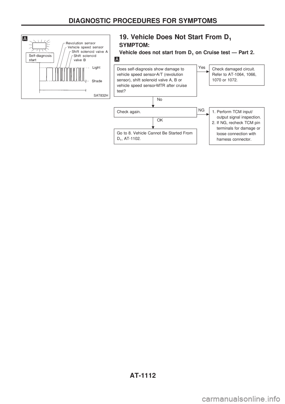
19. Vehicle Does Not Start From D1
SYMPTOM:
Vehicle does not start from D1on Cruise test Ð Part 2.
Does self-diagnosis show damage to
vehicle speed sensorzA/T (revolution
sensor), shift solenoid valve A, B or
vehicle speed sensorzMTR after cruise
test?
No
cYes
Check damaged circuit.
Refer to AT-1064, 1066,
1070 or 1072.
Check again.
OK
cNG
1. Perform TCM input/
output signal inspection.
2. If NG, recheck TCM pin
terminals for damage or
loose connection with
harness connector.
Go to 8. Vehicle Cannot Be Started From
D
1, AT-1102.
SAT832H
. .
.
DIAGNOSTIC PROCEDURES FOR SYMPTOMS
AT-1112
Page 115 of 1033
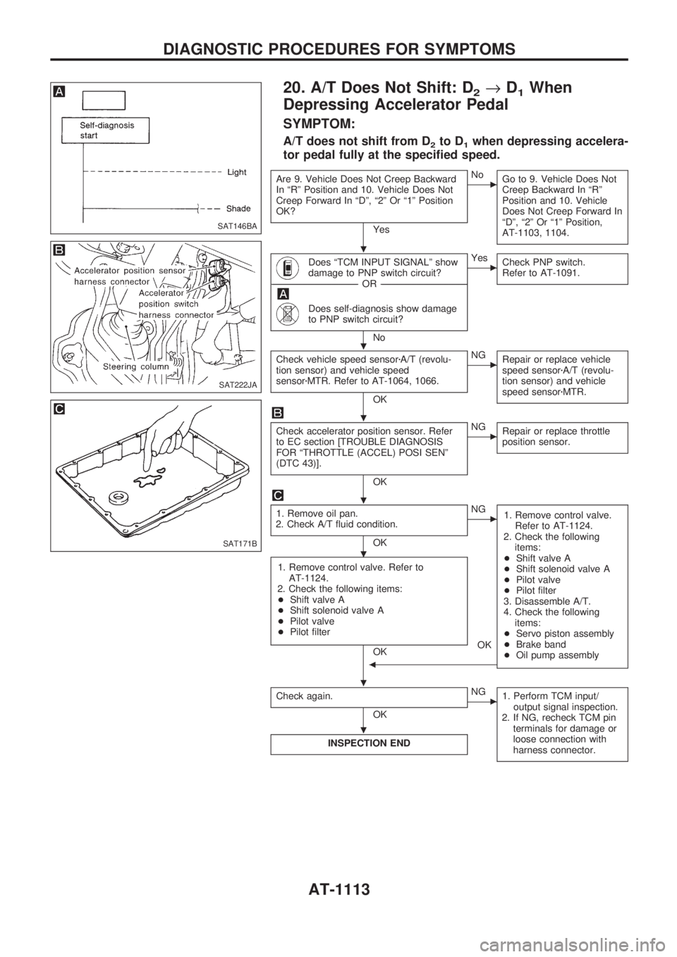
20. A/T Does Not Shift: D2®D1When
Depressing Accelerator Pedal
SYMPTOM:
A/T does not shift from D2to D1when depressing accelera-
tor pedal fully at the specified speed.
Are 9. Vehicle Does Not Creep Backward
In ªRº Position and 10. Vehicle Does Not
Creep Forward In ªDº, ª2º Or ª1º Position
OK?
Yes
cNo
Go to 9. Vehicle Does Not
Creep Backward In ªRº
Position and 10. Vehicle
Does Not Creep Forward In
ªDº, ª2º Or ª1º Position,
AT-1103, 1104.
Does ªTCM INPUT SIGNALº show
damage to PNP switch circuit?
------------------------------------------------------------------------------------------------------------------------------------OR------------------------------------------------------------------------------------------------------------------------------------
Does self-diagnosis show damage
to PNP switch circuit?
No
cYes
Check PNP switch.
Refer to AT-1091.
Check vehicle speed sensorzA/T (revolu-
tion sensor) and vehicle speed
sensorzMTR. Refer to AT-1064, 1066.
OK
cNG
Repair or replace vehicle
speed sensorzA/T (revolu-
tion sensor) and vehicle
speed sensorzMTR.
Check accelerator position sensor. Refer
to EC section [TROUBLE DIAGNOSIS
FOR ªTHROTTLE (ACCEL) POSI SENº
(DTC 43)].
OK
cNG
Repair or replace throttle
position sensor.
1. Remove oil pan.
2. Check A/T fluid condition.
OK
cNG
1. Remove control valve.
Refer to AT-1124.
2. Check the following
items:
+Shift valve A
+Shift solenoid valve A
+Pilot valve
+Pilot filter
3. Disassemble A/T.
4. Check the following
items:
+Servo piston assembly
+Brake band
+Oil pump assembly
1. Remove control valve. Refer to
AT-1124.
2. Check the following items:
+Shift valve A
+Shift solenoid valve A
+Pilot valve
+Pilot filter
OK
b
OK
Check again.
OK
cNG
1. Perform TCM input/
output signal inspection.
2. If NG, recheck TCM pin
terminals for damage or
loose connection with
harness connector.
INSPECTION END
SAT146BA
SAT222JA
SAT171B
.
.
.
.
.
.
.
DIAGNOSTIC PROCEDURES FOR SYMPTOMS
AT-1113
Page 116 of 1033
21. A/T Does Not Shift: D4®D3, When
Overdrive Control Switch ªONº®ªOFFº
SYMPTOM:
A/T does not shift from D4to D3when changing overdrive
control switch to ªOFFº position.
Does ªTCM INPUT SIGNALSº in
Data Monitor show damage to
overdrive control switch circuit?
------------------------------------------------------------------------------------------------------------------------------------OR------------------------------------------------------------------------------------------------------------------------------------
Does self-diagnosis show damage
to overdrive control switch circuit?
No
cYes
Check overdrive control
switch circuit. Refer to
AT-1091.
Go to 10. A/T Does Not Shift: D2®D3,
AT-1104.
22. A/T Does Not Shift: D3®22, When
Selector Lever ªDº®ª2º Position
SYMPTOM:
A/T does not shift from D3to 22when changing selector
lever from ªDº to ª2º position.
Does ªTCM INPUT SIGNALSº in
Data Monitor show damage to
PNP switch circuit?
------------------------------------------------------------------------------------------------------------------------------------OR------------------------------------------------------------------------------------------------------------------------------------
Does self-diagnosis show damage
to PNP switch circuit?
No
cYes
Check PNP switch circuit.
Refer to AT-1091.
Go to 12. A/T Does Not Shift: D1®D2Or Does Not Kickdown: D4®D2,
AT-1106.
SAT146BA
SAT146BA
.
.
DIAGNOSTIC PROCEDURES FOR SYMPTOMS
AT-1114
Page 117 of 1033
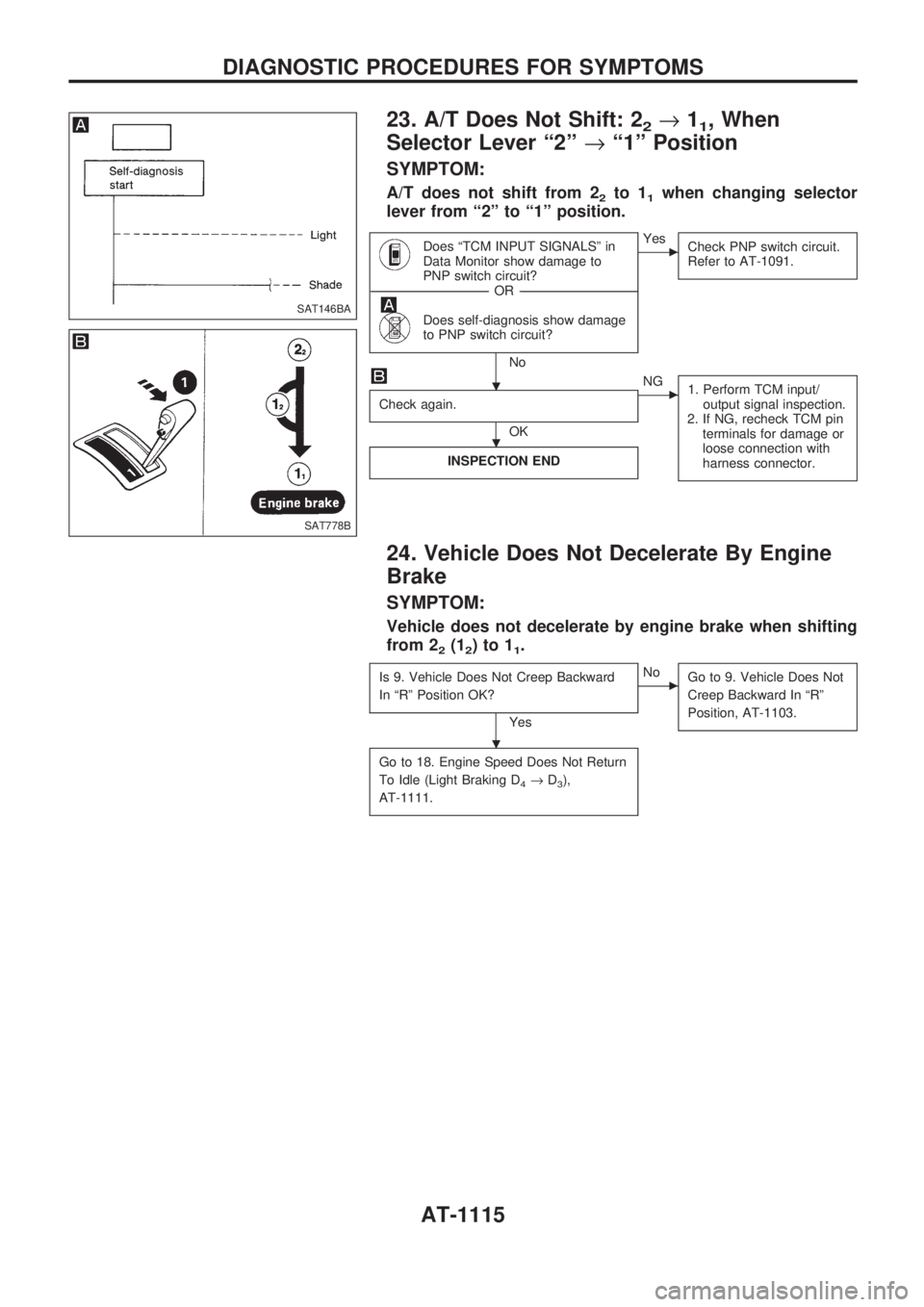
23. A/T Does Not Shift: 22®11, When
Selector Lever ª2º®ª1º Position
SYMPTOM:
A/T does not shift from 22to 11when changing selector
lever from ª2º to ª1º position.
Does ªTCM INPUT SIGNALSº in
Data Monitor show damage to
PNP switch circuit?
------------------------------------------------------------------------------------------------------------------------------------OR------------------------------------------------------------------------------------------------------------------------------------
Does self-diagnosis show damage
to PNP switch circuit?
No
cYes
Check PNP switch circuit.
Refer to AT-1091.
Check again.
OK
cNG
1. Perform TCM input/
output signal inspection.
2. If NG, recheck TCM pin
terminals for damage or
loose connection with
harness connector.
INSPECTION END
24. Vehicle Does Not Decelerate By Engine
Brake
SYMPTOM:
Vehicle does not decelerate by engine brake when shifting
from 2
2(12)to11.
Is 9. Vehicle Does Not Creep Backward
In ªRº Position OK?
Yes
cNo
Go to 9. Vehicle Does Not
Creep Backward In ªRº
Position, AT-1103.
Go to 18. Engine Speed Does Not Return
To Idle (Light Braking D
4®D3),
AT-1111.
SAT146BA
SAT778B
.
.
.
DIAGNOSTIC PROCEDURES FOR SYMPTOMS
AT-1115
Page 118 of 1033
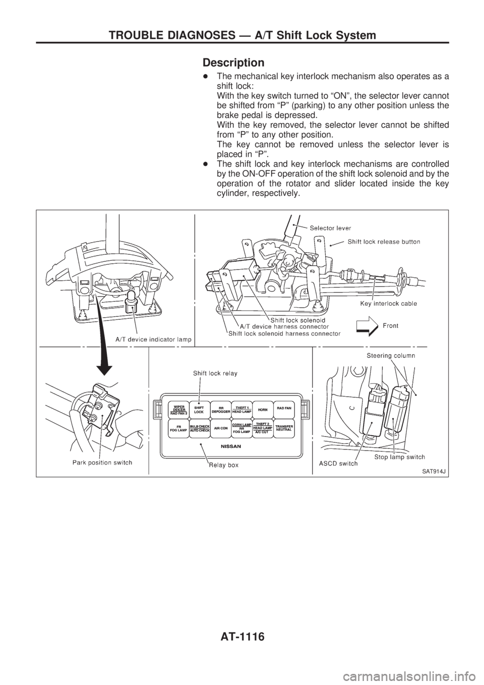
Description
+The mechanical key interlock mechanism also operates as a
shift lock:
With the key switch turned to ªONº, the selector lever cannot
be shifted from ªPº (parking) to any other position unless the
brake pedal is depressed.
With the key removed, the selector lever cannot be shifted
from ªPº to any other position.
The key cannot be removed unless the selector lever is
placed in ªPº.
+The shift lock and key interlock mechanisms are controlled
by the ON-OFF operation of the shift lock solenoid and by the
operation of the rotator and slider located inside the key
cylinder, respectively.
SAT914J
TROUBLE DIAGNOSES Ð A/T Shift Lock System
AT-1116
Page 119 of 1033
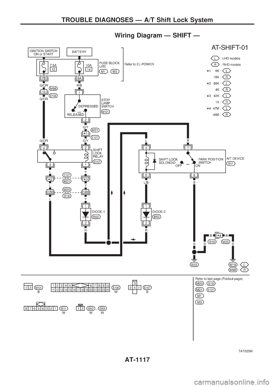
Wiring Diagram Ð SHIFT Ð
TAT025M
TROUBLE DIAGNOSES Ð A/T Shift Lock System
AT-1117
Page 120 of 1033
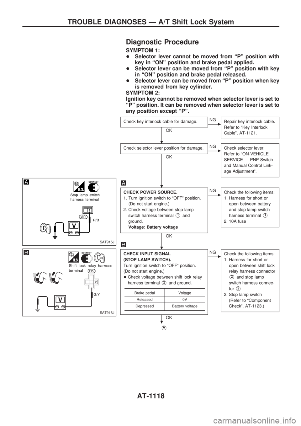
Diagnostic Procedure
SYMPTOM 1:
+Selector lever cannot be moved from ªPº position with
key in ªONº position and brake pedal applied.
+Selector lever can be moved from ªPº position with key
in ªONº position and brake pedal released.
+Selector lever can be moved from ªPº position when key
is removed from key cylinder.
SYMPTOM 2:
Ignition key cannot be removed when selector lever is set to
ªPº position. It can be removed when selector lever is set to
any position except ªPº.
Check key interlock cable for damage.
OK
cNG
Repair key interlock cable.
Refer to ªKey Interlock
Cableº, AT-1121.
Check selector lever position for damage.
OK
cNG
Check selector lever.
Refer to ªON-VEHICLE
SERVICE Ð PNP Switch
and Manual Control Link-
age Adjustmentº.
CHECK POWER SOURCE.
1. Turn ignition switch to ªOFFº position.
(Do not start engine.)
2. Check voltage between stop lamp
switch harness terminal
V1and
ground.
Voltage: Battery voltage
OK
cNG
Check the following items:
1. Harness for short or
open between battery
and stop lamp switch
harness terminal
V1
2. 10A fuse
CHECK INPUT SIGNAL
(STOP LAMP SWITCH).
Turn ignition switch to ªOFFº position.
(Do not start engine.)
+Check voltage between shift lock relay
harness terminal
V2and ground.
OK
cNG
Check the following items:
1. Harness for short or
open between shift lock
relay harness connector
V2and stop lamp
switch harness connec-
tor
V2
2. Stop lamp switch
(Refer to ªComponent
Checkº, AT-1123.)
VA
Brake pedal Voltage
Released 0V
Depressed Battery voltage
SAT915J
SAT916J
.
.
.
.
TROUBLE DIAGNOSES Ð A/T Shift Lock System
AT-1118