NISSAN PATROL 2000 Electronic Repair Manual
PATROL 2000
NISSAN
NISSAN
https://www.carmanualsonline.info/img/5/57367/w960_57367-0.png
NISSAN PATROL 2000 Electronic Repair Manual
Trending: remote start, Audio, egr, wiring, boot, fuel pump, brake sensor
Page 151 of 1033
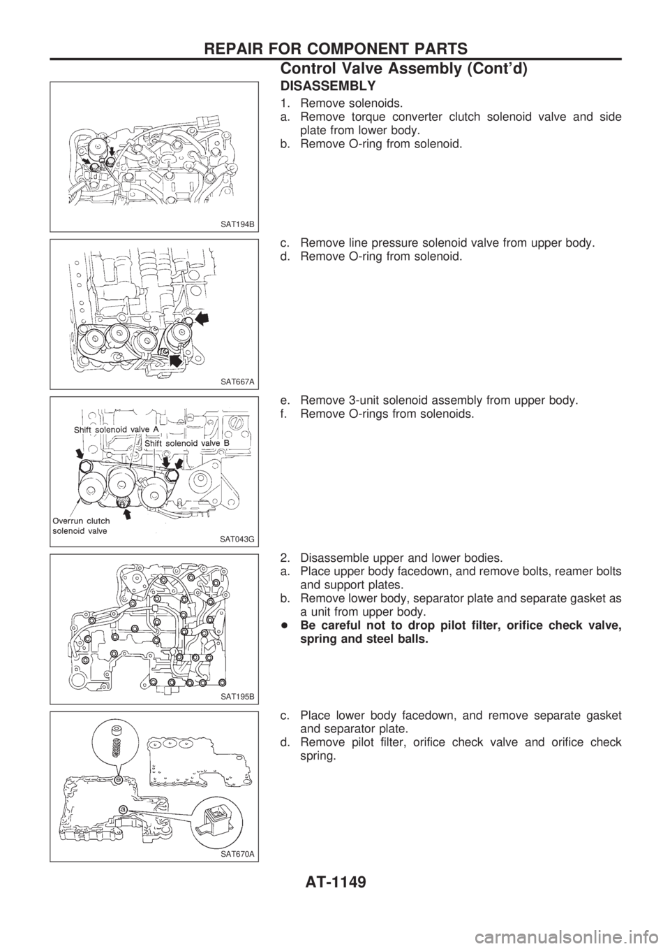
DISASSEMBLY
1. Remove solenoids.
a. Remove torque converter clutch solenoid valve and side
plate from lower body.
b. Remove O-ring from solenoid.
c. Remove line pressure solenoid valve from upper body.
d. Remove O-ring from solenoid.
e. Remove 3-unit solenoid assembly from upper body.
f. Remove O-rings from solenoids.
2. Disassemble upper and lower bodies.
a. Place upper body facedown, and remove bolts, reamer bolts
and support plates.
b. Remove lower body, separator plate and separate gasket as
a unit from upper body.
+Be careful not to drop pilot filter, orifice check valve,
spring and steel balls.
c. Place lower body facedown, and remove separate gasket
and separator plate.
d. Remove pilot filter, orifice check valve and orifice check
spring.
SAT194B
SAT667A
SAT043G
SAT195B
SAT670A
REPAIR FOR COMPONENT PARTS
Control Valve Assembly (Cont'd)
AT-1149
Page 152 of 1033
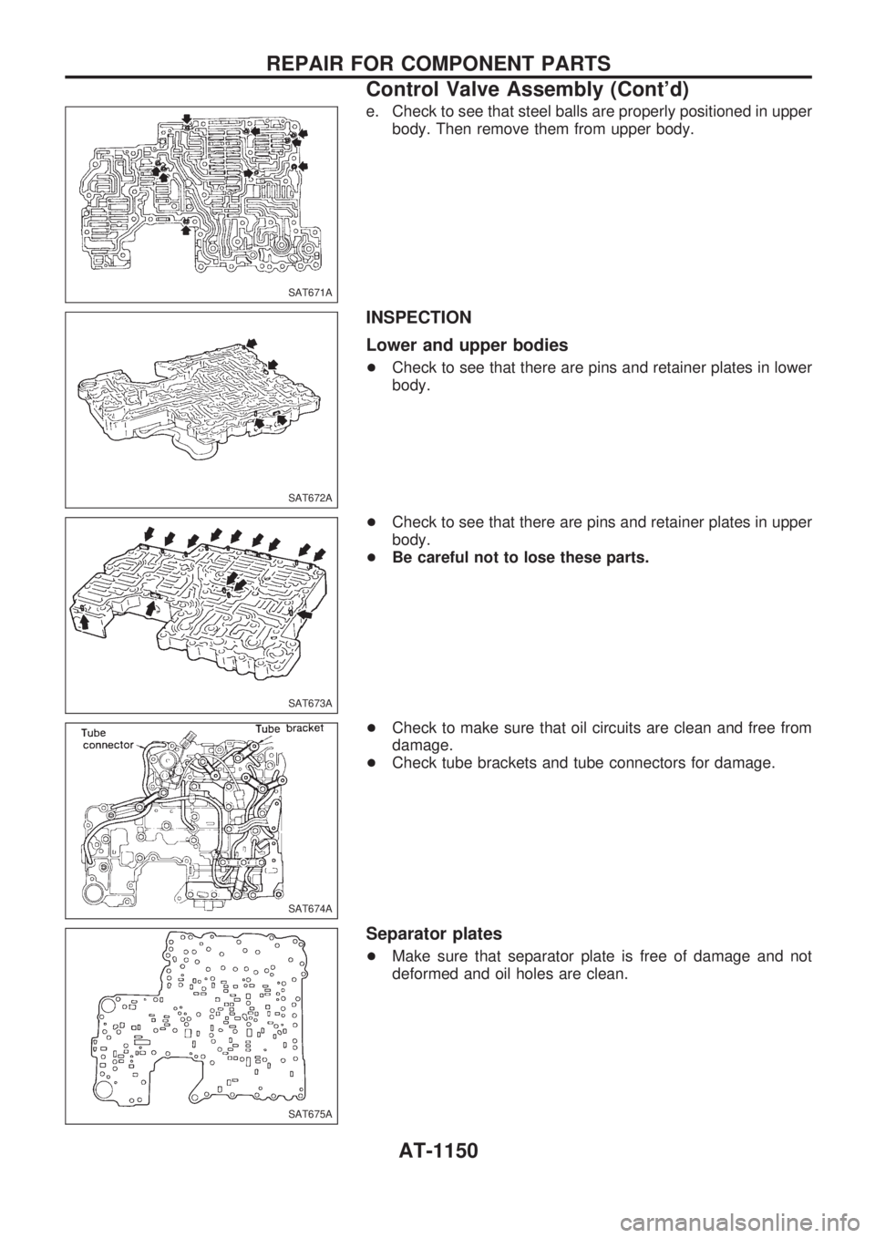
e. Check to see that steel balls are properly positioned in upper
body. Then remove them from upper body.
INSPECTION
Lower and upper bodies
+Check to see that there are pins and retainer plates in lower
body.
+Check to see that there are pins and retainer plates in upper
body.
+Be careful not to lose these parts.
+Check to make sure that oil circuits are clean and free from
damage.
+Check tube brackets and tube connectors for damage.
Separator plates
+Make sure that separator plate is free of damage and not
deformed and oil holes are clean.
SAT671A
SAT672A
SAT673A
SAT674A
SAT675A
REPAIR FOR COMPONENT PARTS
Control Valve Assembly (Cont'd)
AT-1150
Page 153 of 1033
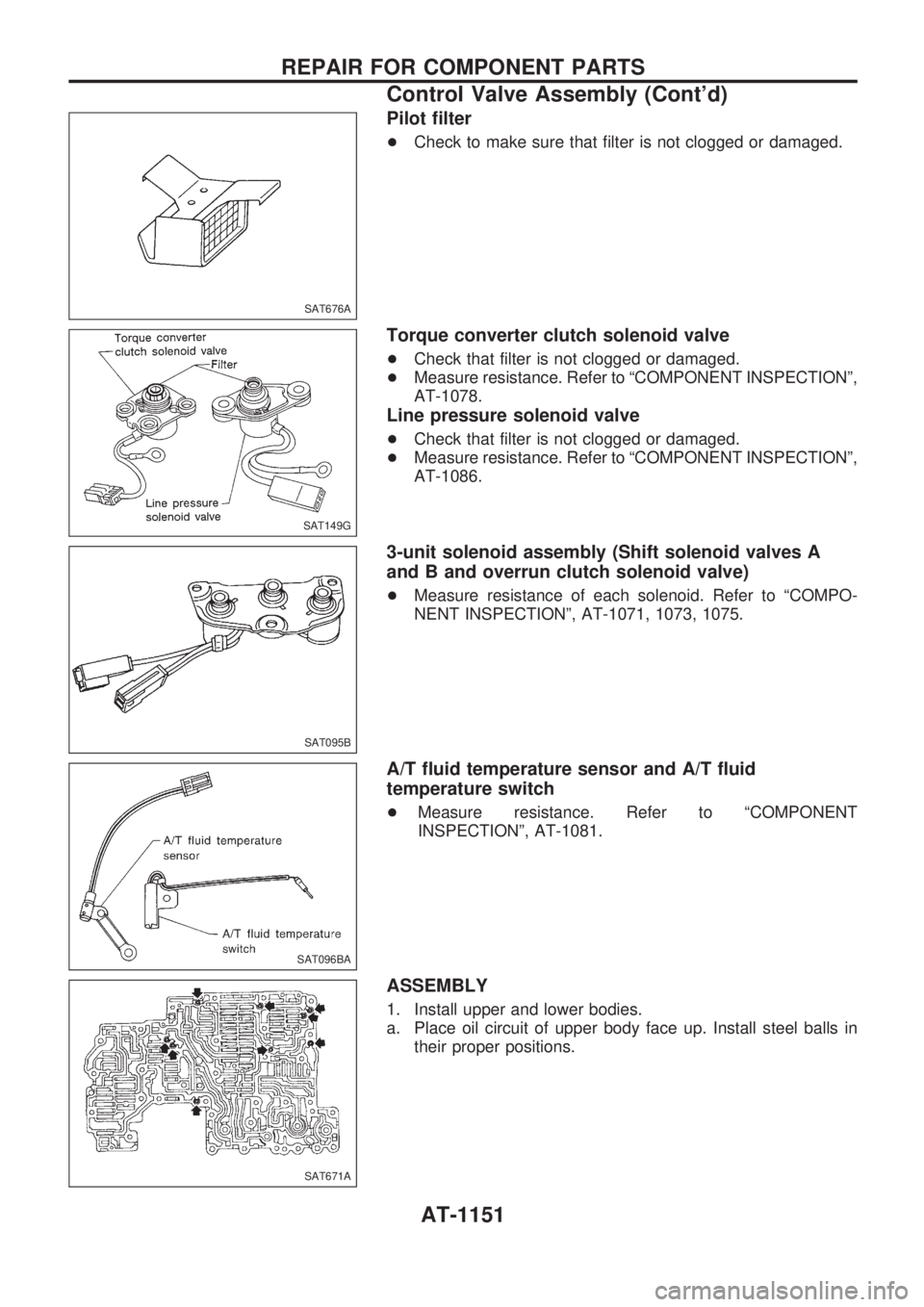
Pilot filter
+Check to make sure that filter is not clogged or damaged.
Torque converter clutch solenoid valve
+Check that filter is not clogged or damaged.
+Measure resistance. Refer to ªCOMPONENT INSPECTIONº,
AT-1078.
Line pressure solenoid valve
+Check that filter is not clogged or damaged.
+Measure resistance. Refer to ªCOMPONENT INSPECTIONº,
AT-1086.
3-unit solenoid assembly (Shift solenoid valves A
and B and overrun clutch solenoid valve)
+Measure resistance of each solenoid. Refer to ªCOMPO-
NENT INSPECTIONº, AT-1071, 1073, 1075.
A/T fluid temperature sensor and A/T fluid
temperature switch
+Measure resistance. Refer to ªCOMPONENT
INSPECTIONº, AT-1081.
ASSEMBLY
1. Install upper and lower bodies.
a. Place oil circuit of upper body face up. Install steel balls in
their proper positions.
SAT676A
SAT149G
SAT095B
SAT096BA
SAT671A
REPAIR FOR COMPONENT PARTS
Control Valve Assembly (Cont'd)
AT-1151
Page 154 of 1033
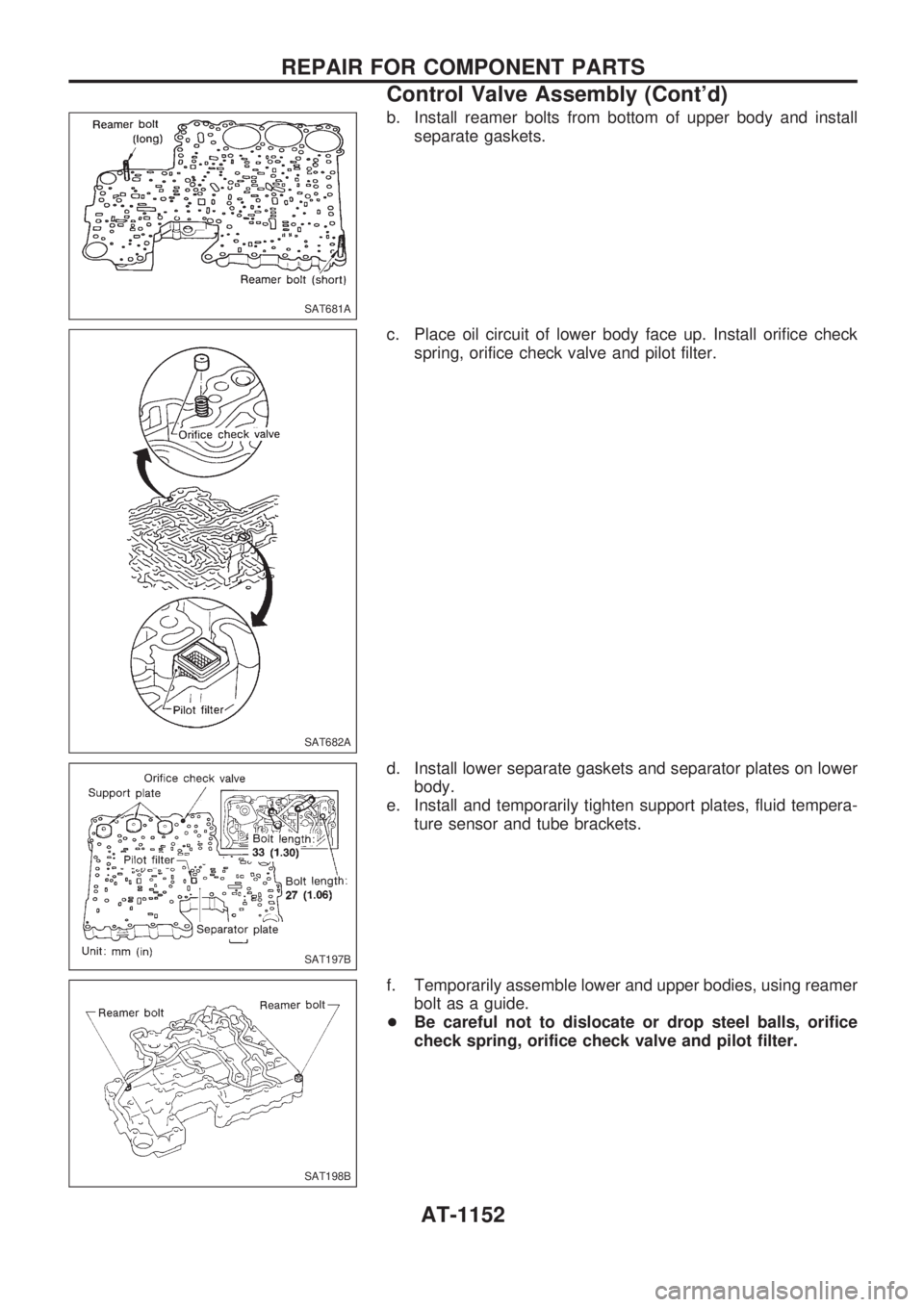
b. Install reamer bolts from bottom of upper body and install
separate gaskets.
c. Place oil circuit of lower body face up. Install orifice check
spring, orifice check valve and pilot filter.
d. Install lower separate gaskets and separator plates on lower
body.
e. Install and temporarily tighten support plates, fluid tempera-
ture sensor and tube brackets.
f. Temporarily assemble lower and upper bodies, using reamer
bolt as a guide.
+Be careful not to dislocate or drop steel balls, orifice
check spring, orifice check valve and pilot filter.
SAT681A
SAT682A
SAT197B
SAT198B
REPAIR FOR COMPONENT PARTS
Control Valve Assembly (Cont'd)
AT-1152
Page 155 of 1033
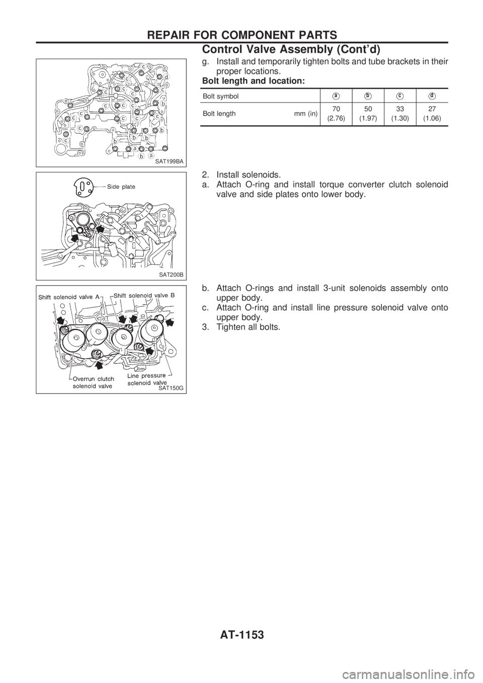
g. Install and temporarily tighten bolts and tube brackets in their
proper locations.
Bolt length and location:
Bolt symbolVaVbVcVd
Bolt length mm (in)70
(2.76)50
(1.97)33
(1.30)27
(1.06)
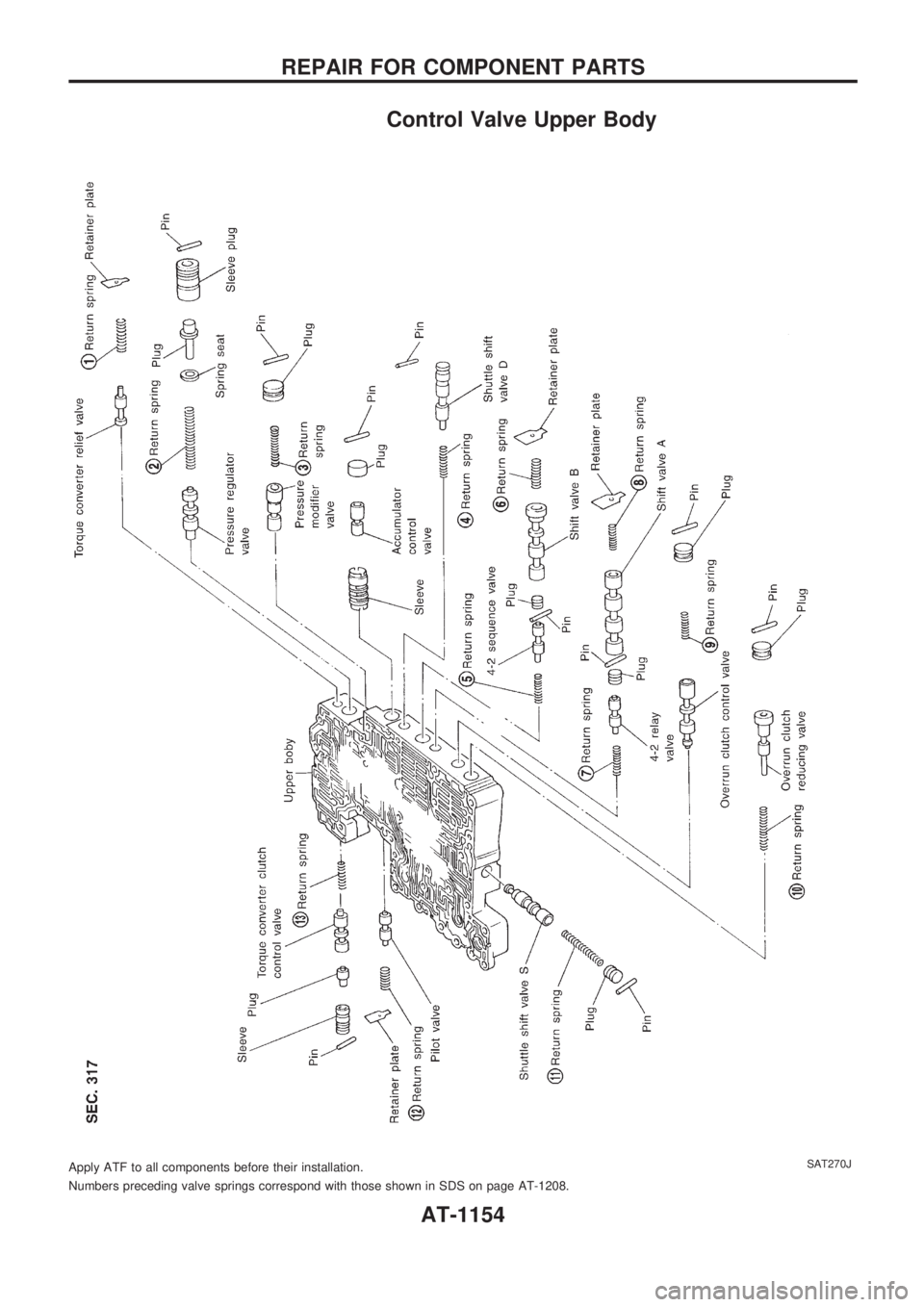
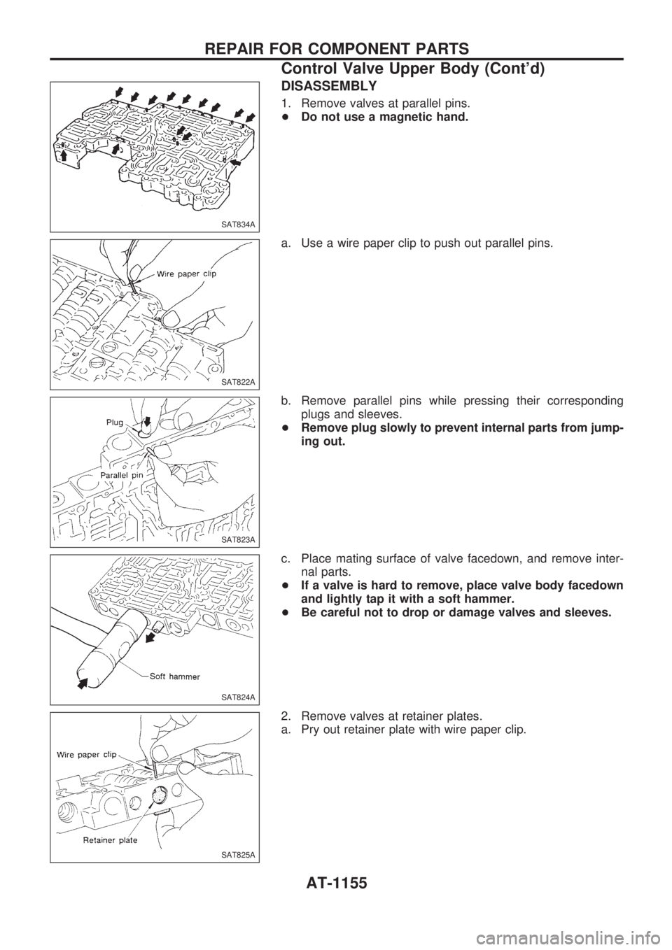
2. Install solenoids.
a. Attach O-ring and install torque converter clutch solenoid
valve and side plates onto lower body.
b. Attach O-rings and install 3-unit solenoids assembly onto
upper body.
c. Attach O-ring and install line pressure solenoid valve onto
upper body.
3. Tighten all bolts.
SAT199BA
SAT200B
SAT150G
REPAIR FOR COMPONENT PARTS
Control Valve Assembly (Cont'd)
AT-1153
Page 156 of 1033
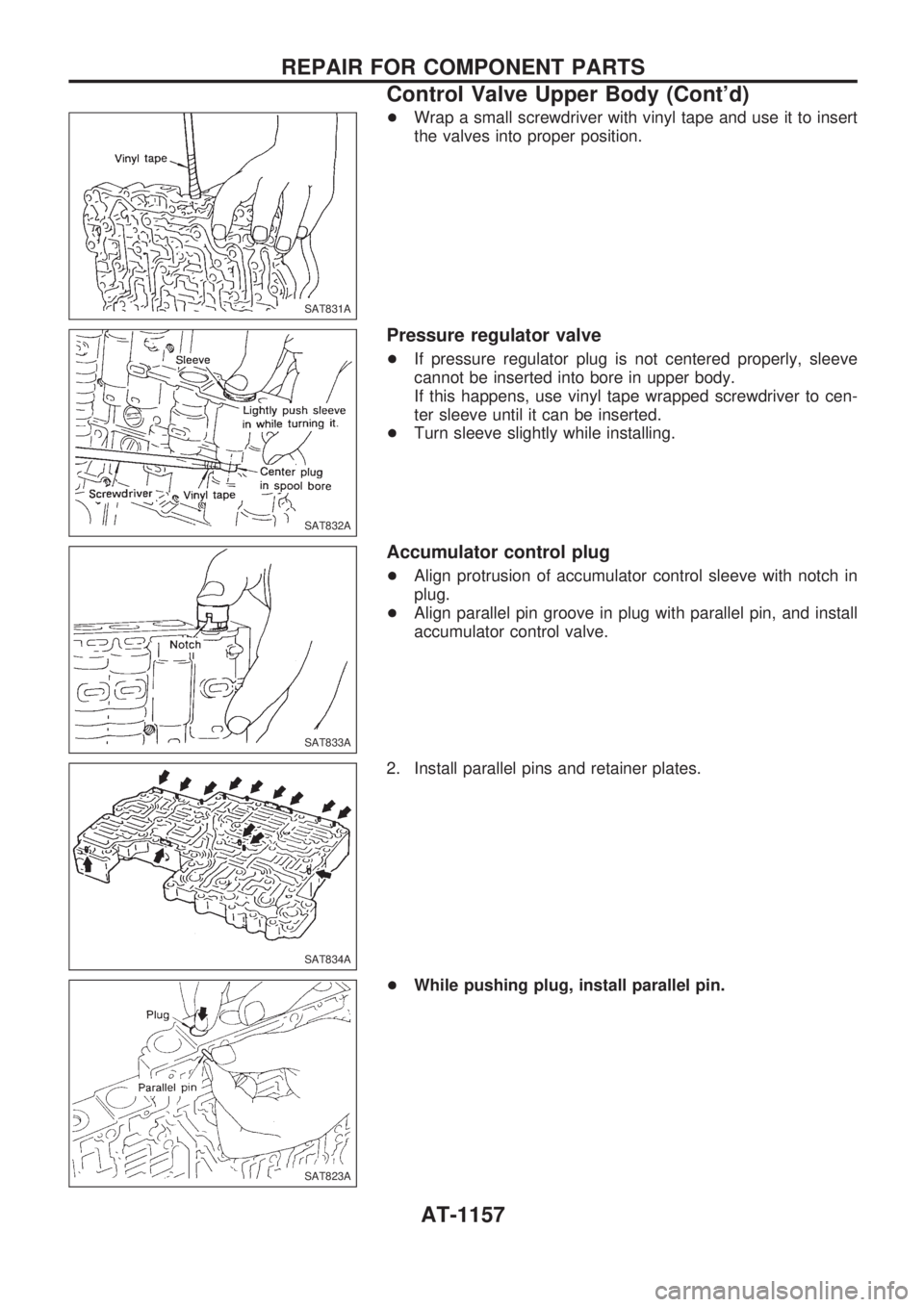
Control Valve Upper Body
Numbers preceding valve springs correspond with those shown in SDS on page AT-1208. Apply ATF to all components before their installation.
SAT270J
REPAIR FOR COMPONENT PARTS
AT-1154
Page 157 of 1033
DISASSEMBLY
1. Remove valves at parallel pins.
+Do not use a magnetic hand.
a. Use a wire paper clip to push out parallel pins.
b. Remove parallel pins while pressing their corresponding
plugs and sleeves.
+Remove plug slowly to prevent internal parts from jump-
ing out.
c. Place mating surface of valve facedown, and remove inter-
nal parts.
+If a valve is hard to remove, place valve body facedown
and lightly tap it with a soft hammer.
+Be careful not to drop or damage valves and sleeves.
2. Remove valves at retainer plates.
a. Pry out retainer plate with wire paper clip.
SAT834A
SAT822A
SAT823A
SAT824A
SAT825A
REPAIR FOR COMPONENT PARTS
Control Valve Upper Body (Cont'd)
AT-1155
Page 158 of 1033
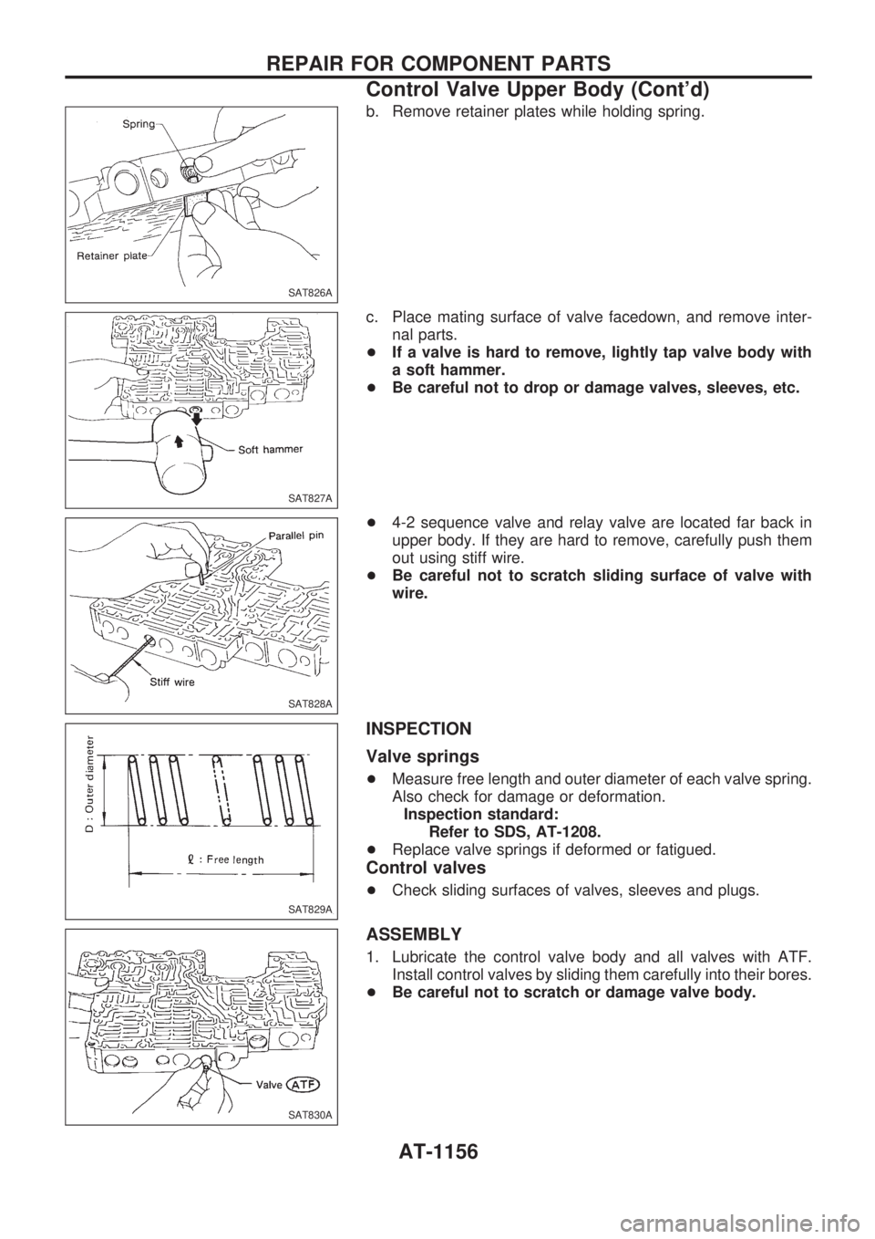
b. Remove retainer plates while holding spring.
c. Place mating surface of valve facedown, and remove inter-
nal parts.
+If a valve is hard to remove, lightly tap valve body with
a soft hammer.
+Be careful not to drop or damage valves, sleeves, etc.
+4-2 sequence valve and relay valve are located far back in
upper body. If they are hard to remove, carefully push them
out using stiff wire.
+Be careful not to scratch sliding surface of valve with
wire.
INSPECTION
Valve springs
+Measure free length and outer diameter of each valve spring.
Also check for damage or deformation.
Inspection standard:
Refer to SDS, AT-1208.
+Replace valve springs if deformed or fatigued.
Control valves
+Check sliding surfaces of valves, sleeves and plugs.
ASSEMBLY
1. Lubricate the control valve body and all valves with ATF.
Install control valves by sliding them carefully into their bores.
+Be careful not to scratch or damage valve body.
SAT826A
SAT827A
SAT828A
SAT829A
SAT830A
REPAIR FOR COMPONENT PARTS
Control Valve Upper Body (Cont'd)
AT-1156
Page 159 of 1033
+Wrap a small screwdriver with vinyl tape and use it to insert
the valves into proper position.
Pressure regulator valve
+If pressure regulator plug is not centered properly, sleeve
cannot be inserted into bore in upper body.
If this happens, use vinyl tape wrapped screwdriver to cen-
ter sleeve until it can be inserted.
+Turn sleeve slightly while installing.
Accumulator control plug
+Align protrusion of accumulator control sleeve with notch in
plug.
+Align parallel pin groove in plug with parallel pin, and install
accumulator control valve.
2. Install parallel pins and retainer plates.
+While pushing plug, install parallel pin.
SAT831A
SAT832A
SAT833A
SAT834A
SAT823A
REPAIR FOR COMPONENT PARTS
Control Valve Upper Body (Cont'd)
AT-1157
Page 160 of 1033
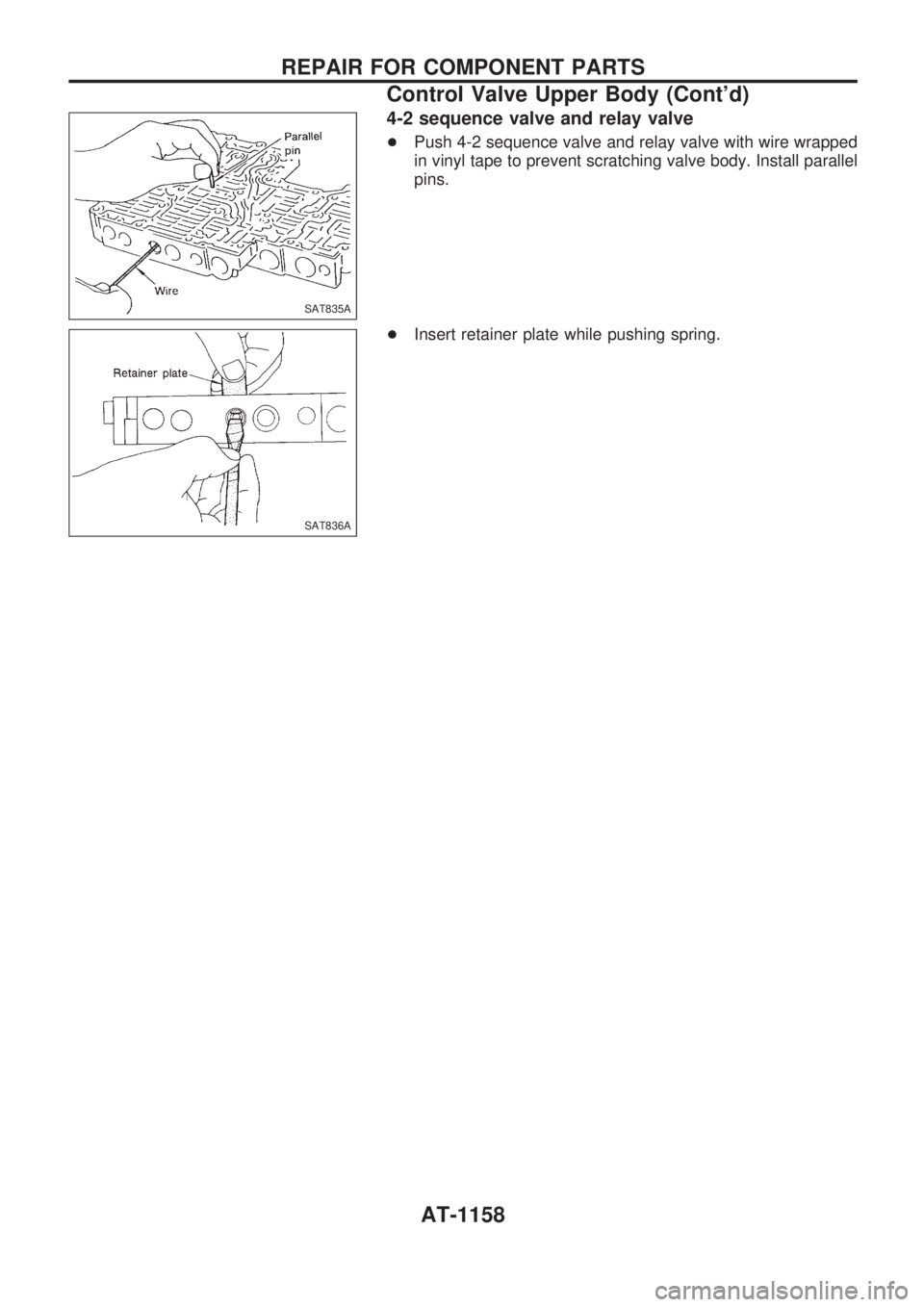
4-2 sequence valve and relay valve
+Push 4-2 sequence valve and relay valve with wire wrapped
in vinyl tape to prevent scratching valve body. Install parallel
pins.
+Insert retainer plate while pushing spring.
SAT835A
SAT836A
REPAIR FOR COMPONENT PARTS
Control Valve Upper Body (Cont'd)
AT-1158
Trending: display, engine overheat, coolant capacity, rpm, wiper fluid, air suspension, overheating
