NISSAN PATROL 2000 Electronic Repair Manual
Manufacturer: NISSAN, Model Year: 2000, Model line: PATROL, Model: NISSAN PATROL 2000Pages: 1033, PDF Size: 30.71 MB
Page 501 of 1033
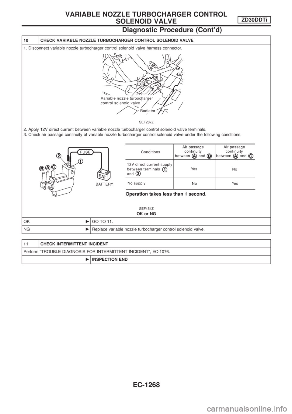
10 CHECK VARIABLE NOZZLE TURBOCHARGER CONTROL SOLENOID VALVE
1. Disconnect variable nozzle turbocharger control solenoid valve harness connector.
SEF287Z
2. Apply 12V direct current between variable nozzle turbocharger control solenoid valve terminals.
3. Check air passage continuity of variable nozzle turbocharger control solenoid valve under the following conditions.
SEF454Z
OK or NG
OKcGO TO 11.
NGcReplace variable nozzle turbocharger control solenoid valve.
11 CHECK INTERMITTENT INCIDENT
Perform ªTROUBLE DIAGNOSIS FOR INTERMITTENT INCIDENTº, EC-1076.
cINSPECTION END
VARIABLE NOZZLE TURBOCHARGER CONTROL
SOLENOID VALVEZD30DDTi
Diagnostic Procedure (Cont'd)
EC-1268
Page 502 of 1033
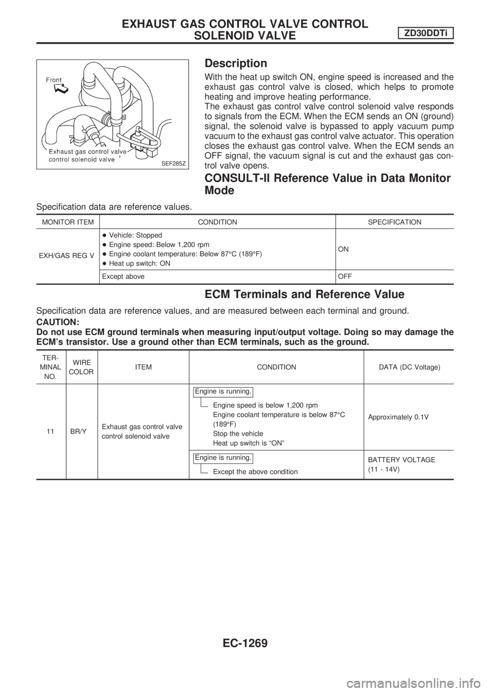
Description
With the heat up switch ON, engine speed is increased and the
exhaust gas control valve is closed, which helps to promote
heating and improve heating performance.
The exhaust gas control valve control solenoid valve responds
to signals from the ECM. When the ECM sends an ON (ground)
signal, the solenoid valve is bypassed to apply vacuum pump
vacuum to the exhaust gas control valve actuator. This operation
closes the exhaust gas control valve. When the ECM sends an
OFF signal, the vacuum signal is cut and the exhaust gas con-
trol valve opens.
CONSULT-II Reference Value in Data Monitor
Mode
Specification data are reference values.
MONITOR ITEM CONDITION SPECIFICATION
EXH/GAS REG V+Vehicle: Stopped
+Engine speed: Below 1,200 rpm
+Engine coolant temperature: Below 87ÉC (189ÉF)
+Heat up switch: ONON
Except above OFF
ECM Terminals and Reference Value
Specification data are reference values, and are measured between each terminal and ground.
CAUTION:
Do not use ECM ground terminals when measuring input/output voltage. Doing so may damage the
ECM's transistor. Use a ground other than ECM terminals, such as the ground.
TER-
MINAL
NO.WIRE
COLORITEM CONDITION DATA (DC Voltage)
11 BR/YExhaust gas control valve
control solenoid valveEngine is running.
Engine speed is below 1,200 rpm
Engine coolant temperature is below 87ÉC
(189ÉF)
Stop the vehicle
Heat up switch is ªONºApproximately 0.1V
Engine is running.
Except the above conditionBATTERY VOLTAGE
(11 - 14V)
SEF285Z
EXHAUST GAS CONTROL VALVE CONTROL
SOLENOID VALVEZD30DDTi
EC-1269
Page 503 of 1033
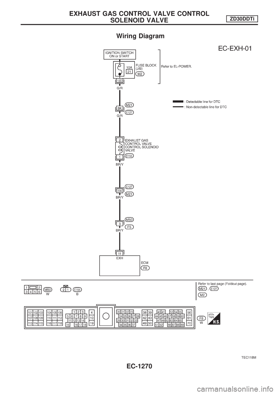
Wiring Diagram
TEC118M
EXHAUST GAS CONTROL VALVE CONTROL
SOLENOID VALVEZD30DDTi
EC-1270
Page 504 of 1033
Diagnostic Procedure
1 INSPECTION START
Do you have CONSULT-II?
Yes or No
YescGO TO 2.
NocGO TO 3.
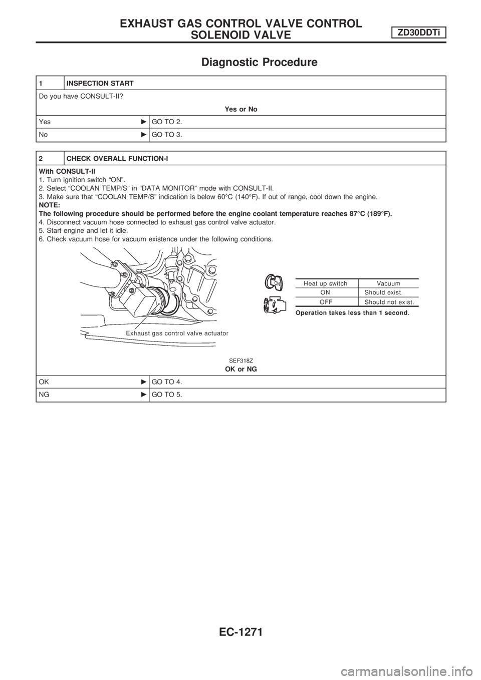
2 CHECK OVERALL FUNCTION-I
With CONSULT-II
1. Turn ignition switch ªONº.
2. Select ªCOOLAN TEMP/Sº in ªDATA MONITORº mode with CONSULT-II.
3. Make sure that ªCOOLAN TEMP/Sº indication is below 60ÉC (140ÉF). If out of range, cool down the engine.
NOTE:
The following procedure should be performed before the engine coolant temperature reaches 87ÉC (189ÉF).
4. Disconnect vacuum hose connected to exhaust gas control valve actuator.
5. Start engine and let it idle.
6. Check vacuum hose for vacuum existence under the following conditions.
SEF318Z
OK or NG
OKcGO TO 4.
NGcGO TO 5.
EXHAUST GAS CONTROL VALVE CONTROL
SOLENOID VALVEZD30DDTi
EC-1271
Page 505 of 1033
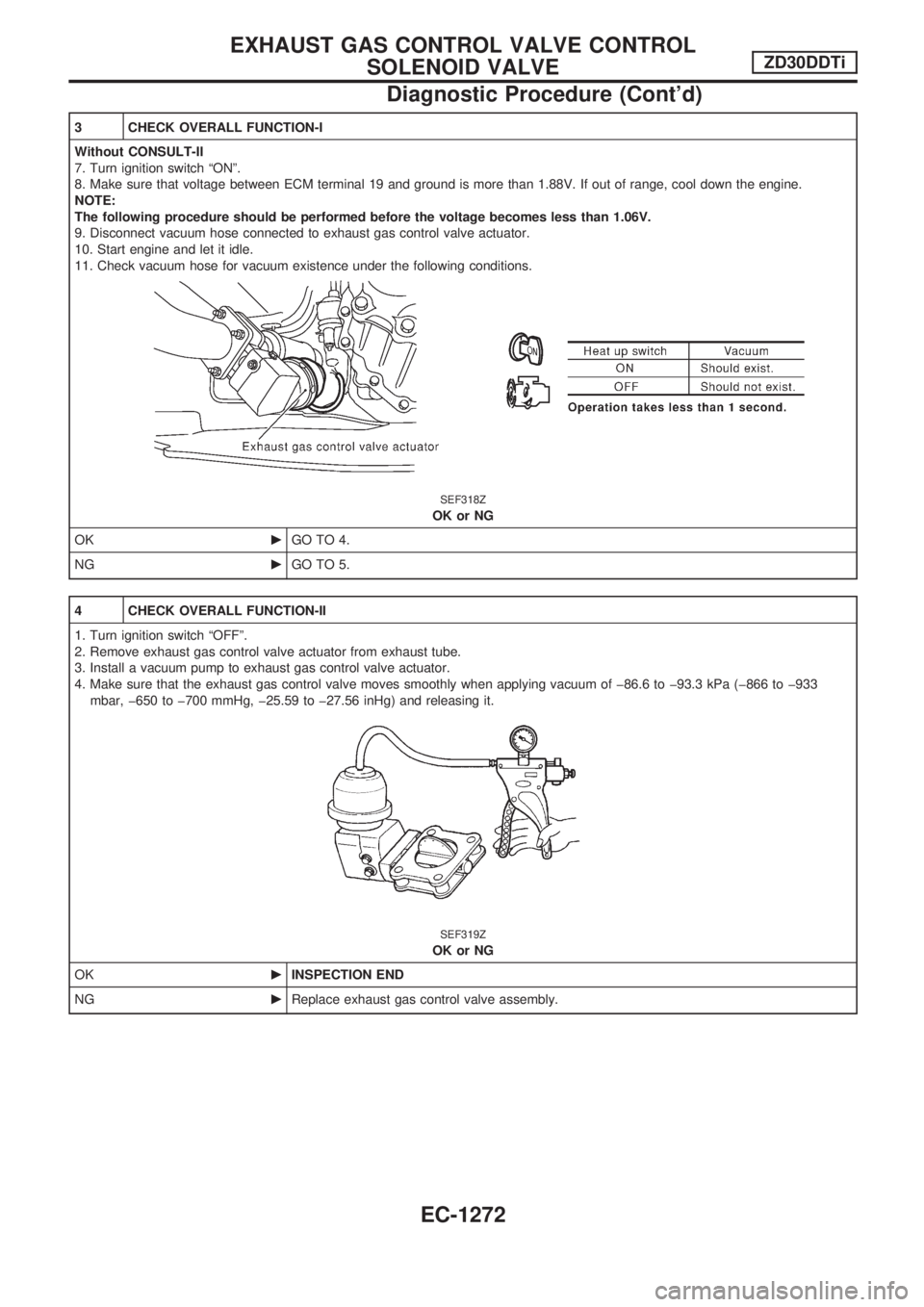
3 CHECK OVERALL FUNCTION-I
Without CONSULT-II
7. Turn ignition switch ªONº.
8. Make sure that voltage between ECM terminal 19 and ground is more than 1.88V. If out of range, cool down the engine.
NOTE:
The following procedure should be performed before the voltage becomes less than 1.06V.
9. Disconnect vacuum hose connected to exhaust gas control valve actuator.
10. Start engine and let it idle.
11. Check vacuum hose for vacuum existence under the following conditions.
SEF318Z
OK or NG
OKcGO TO 4.
NGcGO TO 5.
4 CHECK OVERALL FUNCTION-II
1. Turn ignition switch ªOFFº.
2. Remove exhaust gas control valve actuator from exhaust tube.
3. Install a vacuum pump to exhaust gas control valve actuator.
4. Make sure that the exhaust gas control valve moves smoothly when applying vacuum of þ86.6 to þ93.3 kPa (þ866 to þ933
mbar, þ650 to þ700 mmHg, þ25.59 to þ27.56 inHg) and releasing it.
SEF319Z
OK or NG
OKcINSPECTION END
NGcReplace exhaust gas control valve assembly.
EXHAUST GAS CONTROL VALVE CONTROL
SOLENOID VALVEZD30DDTi
Diagnostic Procedure (Cont'd)
EC-1272
Page 506 of 1033
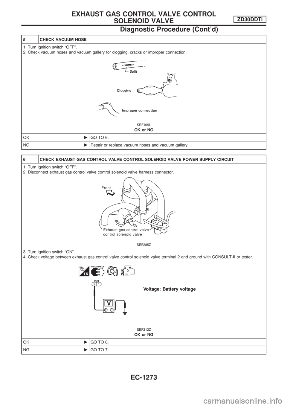
5 CHECK VACUUM HOSE
1. Turn ignition switch ªOFFº.
2. Check vacuum hoses and vacuum gallery for clogging, cracks or improper connection.
SEF109L
OK or NG
OKcGO TO 6.
NGcRepair or replace vacuum hoses and vacuum gallery.
6 CHECK EXHAUST GAS CONTROL VALVE CONTROL SOLENOID VALVE POWER SUPPLY CIRCUIT
1. Turn ignition switch ªOFFº.
2. Disconnect exhaust gas control valve control solenoid valve harness connector.
SEF285Z
3. Turn ignition switch ªONº.
4. Check voltage between exhaust gas control valve control solenoid valve terminal 2 and ground with CONSULT-II or tester.
SEF312Z
OK or NG
OKcGO TO 8.
NGcGO TO 7.
EXHAUST GAS CONTROL VALVE CONTROL
SOLENOID VALVEZD30DDTi
Diagnostic Procedure (Cont'd)
EC-1273
Page 507 of 1033
7 DETECT MALFUNCTIONING PART
Check the following.
+Harness connectors M21, E127
+Fuse block (J/B) connector M2
+10A fuse
+Harness for open or short between exhaust gas control valve control solenoid valve and fuse
cRepair open circuit or short to ground or short to power in harness or connectors.
8 CHECK EXHAUST GAS CONTROL VALVE CONTROL SOLENOID VALVE OUTPUT SIGNAL CIRCUIT FOR OPEN
OR SHORT
1. Turn ignition switch ªOFFº.
2. Disconnect ECM harness connector.
3. Check harness continuity between ECM terminal 11 and exhaust gas control valve control solenoid valve terminal 1. Refer to
Wiring Diagram.
Continuity should exist.
4. Also check harness for short to ground and short to power.
OK or NG
OKcGO TO 10.
NGcGO TO 9.
9 DETECT MALFUNCTIONING PART
Check the following.
+Harness connectors M21, E127
+Harness connectors M50, F5
+Harness for open or short between exhaust gas control valve control solenoid valve and ECM
cRepair open circuit or short to ground or short to power in harness or connectors.
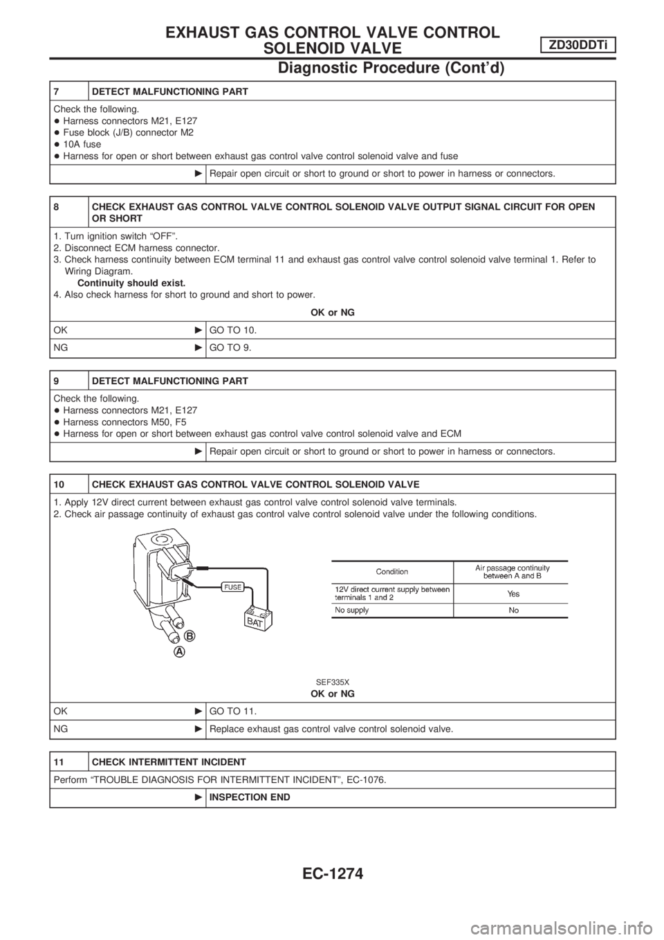
10 CHECK EXHAUST GAS CONTROL VALVE CONTROL SOLENOID VALVE
1. Apply 12V direct current between exhaust gas control valve control solenoid valve terminals.
2. Check air passage continuity of exhaust gas control valve control solenoid valve under the following conditions.
SEF335X
OK or NG
OKcGO TO 11.
NGcReplace exhaust gas control valve control solenoid valve.
11 CHECK INTERMITTENT INCIDENT
Perform ªTROUBLE DIAGNOSIS FOR INTERMITTENT INCIDENTº, EC-1076.
cINSPECTION END
EXHAUST GAS CONTROL VALVE CONTROL
SOLENOID VALVEZD30DDTi
Diagnostic Procedure (Cont'd)
EC-1274
Page 508 of 1033
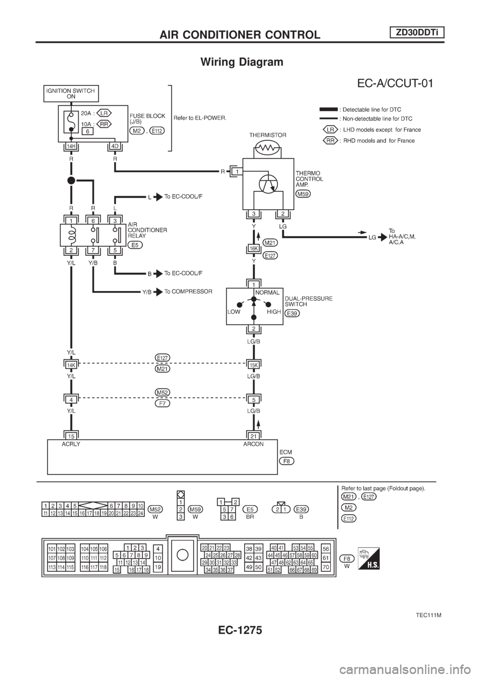
Wiring Diagram
TEC111M
AIR CONDITIONER CONTROLZD30DDTi
EC-1275
Page 509 of 1033
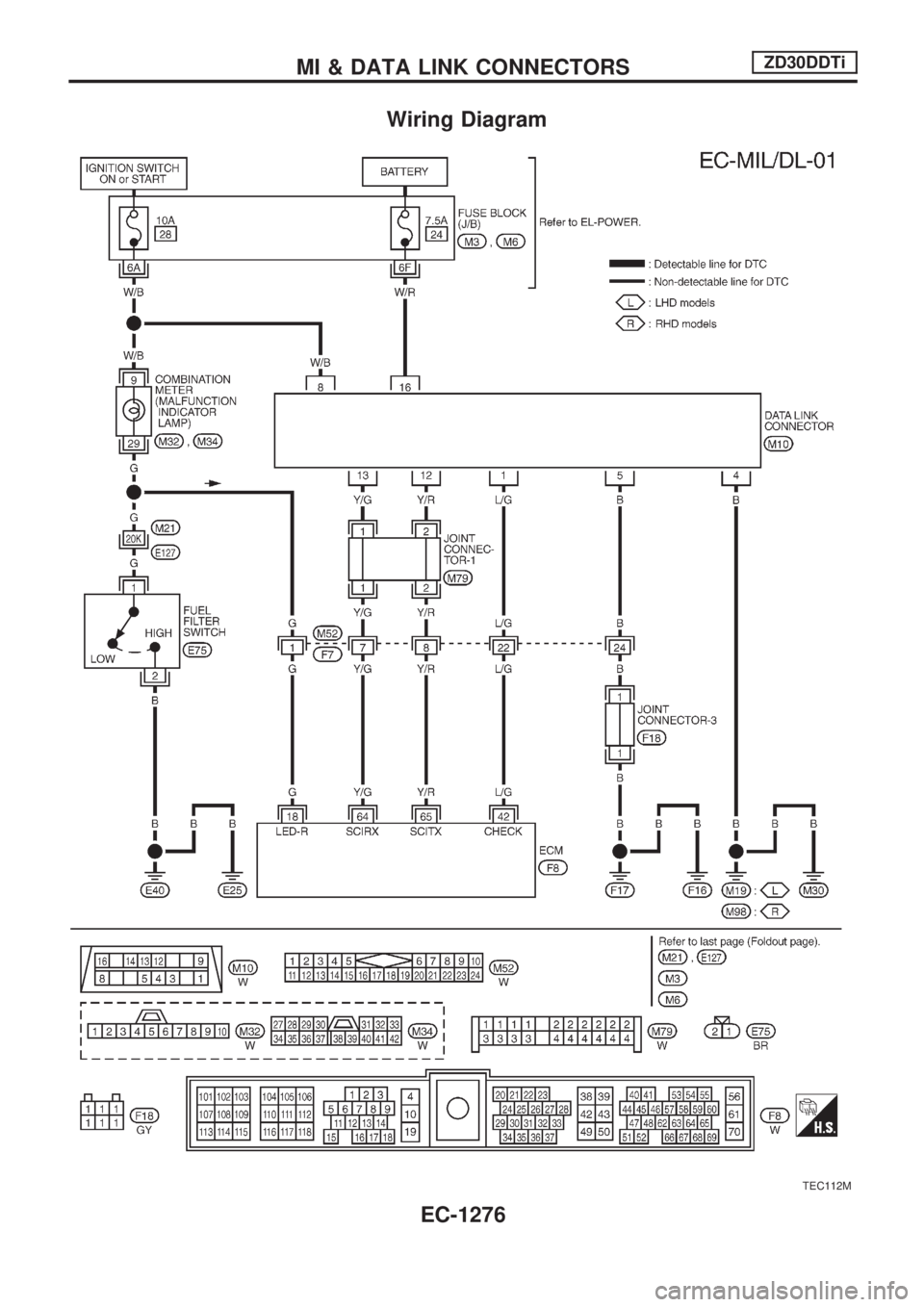
Wiring Diagram
TEC112M
MI & DATA LINK CONNECTORSZD30DDTi
EC-1276
Page 510 of 1033
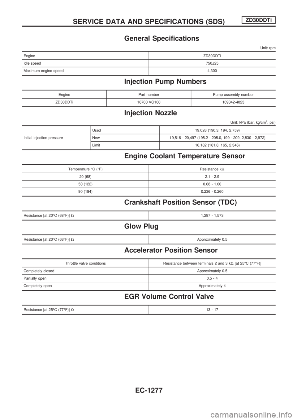
General Specifications
Unit: rpm
EngineZD30DDTi
Idle speed750 25
Maximum engine speed4,300
Injection Pump Numbers
Engine Part number Pump assembly number
ZD30DDTi 16700 VG100 109342-4023
Injection Nozzle
Unit: kPa (bar, kg/cm2, psi)
Initial injection pressureUsed 19,026 (190.3, 194, 2,759)
New 19,516 - 20,497 (195.2 - 205.0, 199 - 209, 2,830 - 2,972)
Limit 16,182 (161.8, 165, 2,346)
Engine Coolant Temperature Sensor
Temperature ÉC (ÉF) Resistance kW
20 (68) 2.1 - 2.9
50 (122) 0.68 - 1.00
90 (194) 0.236 - 0.260
Crankshaft Position Sensor (TDC)
Resistance [at 20ÉC (68ÉF)]W1,287 - 1,573
Glow Plug
Resistance [at 20ÉC (68ÉF)]WApproximately 0.5
Accelerator Position Sensor
Throttle valve conditions Resistance between terminals 2 and 3 kW[at 25ÉC (77ÉF)]
Completely closedApproximately 0.5
Partially open0.5-4
Completely openApproximately 4
EGR Volume Control Valve
Resistance [at 25ÉC (77ÉF)]W13-17
SERVICE DATA AND SPECIFICATIONS (SDS)ZD30DDTi
EC-1277