NISSAN PATROL 2000 Electronic Repair Manual
Manufacturer: NISSAN, Model Year: 2000, Model line: PATROL, Model: NISSAN PATROL 2000Pages: 1033, PDF Size: 30.71 MB
Page 921 of 1033
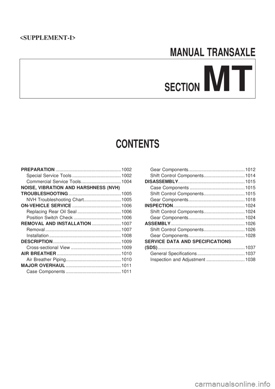
MANUAL TRANSAXLE
SECTION
MT
CONTENTS
PREPARATION................................................... 1002
Special Service Tools ...................................... 1002
Commercial Service Tools ............................... 1004
NOISE, VIBRATION AND HARSHNESS (NVH)
TROUBLESHOOTING......................................... 1005
NVH Troubleshooting Chart............................. 1005
ON-VEHICLE SERVICE...................................... 1006
Replacing Rear Oil Seal .................................. 1006
Position Switch Check ..................................... 1006
REMOVAL AND INSTALLATION....................... 1007
Removal ........................................................... 1007
Installation ........................................................ 1008
DESCRIPTION..................................................... 1009
Cross-sectional View ....................................... 1009
AIR BREATHER.................................................. 1010
Air Breather Piping........................................... 1010
MAJOR OVERHAUL........................................... 1011
Case Components ........................................... 1011Gear Components............................................ 1012
Shift Control Components................................ 1014
DISASSEMBLY.................................................... 1015
Case Components ........................................... 1015
Shift Control Components................................ 1015
Gear Components............................................ 1018
INSPECTION........................................................ 1024
Shift Control Components................................ 1024
Gear Components............................................ 1024
ASSEMBLY.......................................................... 1026
Shift Control Components................................ 1026
Gear Components............................................ 1028
SERVICE DATA AND SPECIFICATIONS
(SDS).................................................................... 1037
General Specifications ..................................... 1037
Inspection and Adjustment .............................. 1038
Page 922 of 1033
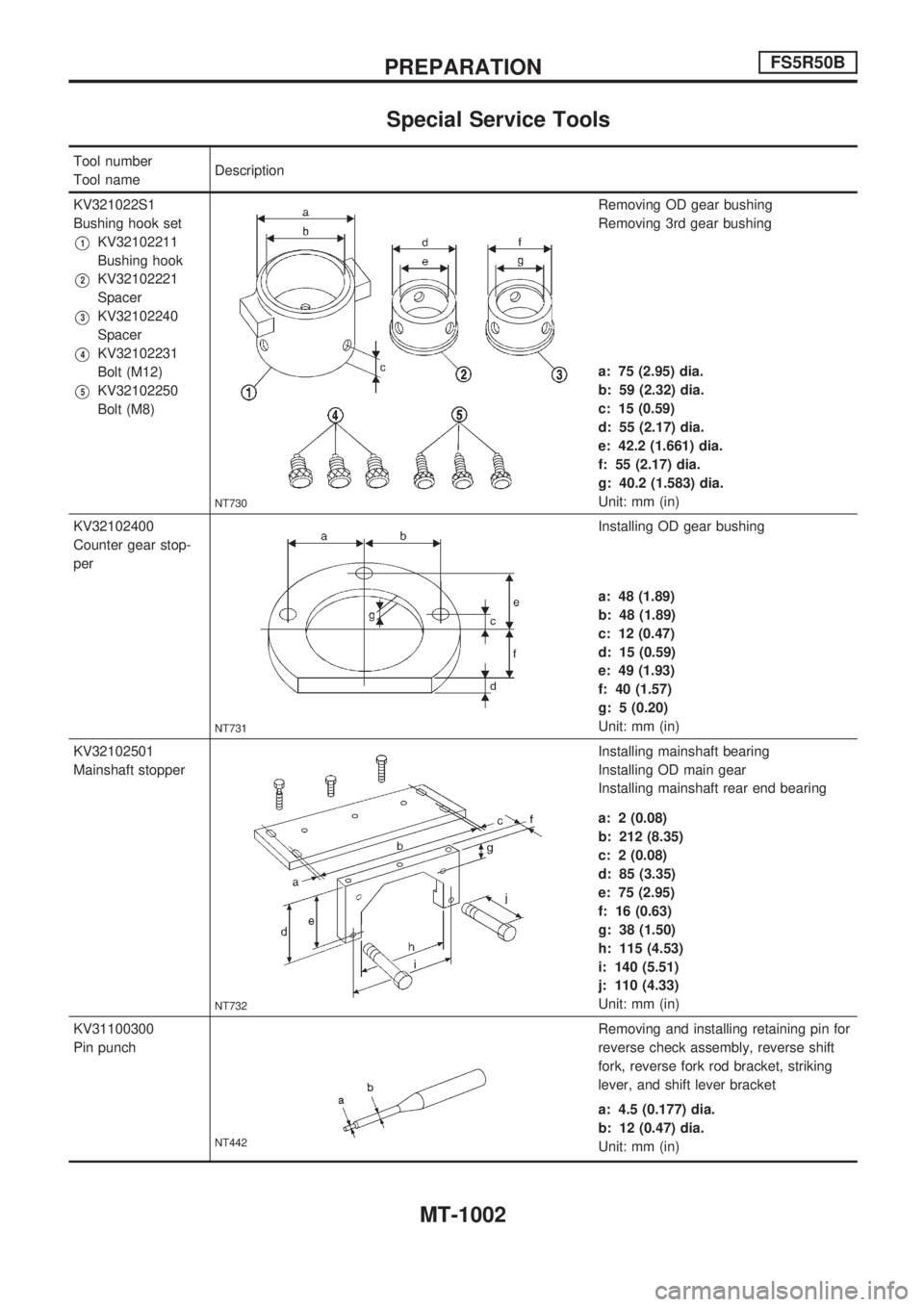
Special Service Tools
Tool number
Tool nameDescription
KV321022S1
Bushing hook set
V1KV32102211
Bushing hook
V2KV32102221
Spacer
V3KV32102240
Spacer
V4KV32102231
Bolt (M12)
V5KV32102250
Bolt (M8)
NT730
Removing OD gear bushing
Removing 3rd gear bushing
a: 75 (2.95) dia.
b: 59 (2.32) dia.
c: 15 (0.59)
d: 55 (2.17) dia.
e: 42.2 (1.661) dia.
f: 55 (2.17) dia.
g: 40.2 (1.583) dia.
Unit: mm (in)
KV32102400
Counter gear stop-
per
NT731
Installing OD gear bushing
a: 48 (1.89)
b: 48 (1.89)
c: 12 (0.47)
d: 15 (0.59)
e: 49 (1.93)
f: 40 (1.57)
g: 5 (0.20)
Unit: mm (in)
KV32102501
Mainshaft stopper
NT732
Installing mainshaft bearing
Installing OD main gear
Installing mainshaft rear end bearing
a: 2 (0.08)
b: 212 (8.35)
c: 2 (0.08)
d: 85 (3.35)
e: 75 (2.95)
f: 16 (0.63)
g: 38 (1.50)
h: 115 (4.53)
i: 140 (5.51)
j: 110 (4.33)
Unit: mm (in)
KV31100300
Pin punch
NT442
Removing and installing retaining pin for
reverse check assembly, reverse shift
fork, reverse fork rod bracket, striking
lever, and shift lever bracket
a: 4.5 (0.177) dia.
b: 12 (0.47) dia.
Unit: mm (in)
PREPARATIONFS5R50B
MT-1002
Page 923 of 1033
Tool number
Tool nameDescription
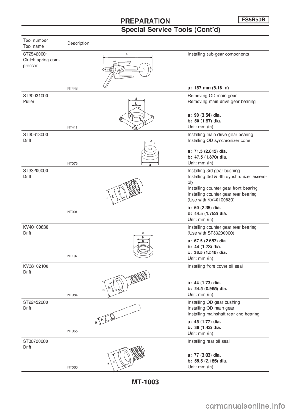
ST25420001
Clutch spring com-
pressor
NT443
Installing sub-gear components
a: 157 mm (6.18 in)
ST30031000
Puller
NT411
Removing OD main gear
Removing main drive gear bearing
a: 90 (3.54) dia.
b: 50 (1.97) dia.
Unit: mm (in)
ST30613000
Drift
NT073
Installing main drive gear bearing
Installing OD synchronizer cone
a: 71.5 (2.815) dia.
b: 47.5 (1.870) dia.
Unit: mm (in)
ST33200000
Drift
NT091
Installing 3rd gear bushing
Installing 3rd & 4th synchronizer assem-
bly
Installing counter gear front bearing
Installing counter gear rear bearing
(Use with KV40100630)
a: 60 (2.36) dia.
b: 44.5 (1.752) dia.
Unit: mm (in)
KV40100630
Drift
NT107
Installing counter gear rear bearing
(Use with ST33200000)
a: 67.5 (2.657) dia.
b: 44 (1.73) dia.
c: 38.5 (1.516) dia.
Unit: mm (in)
KV38102100
Drift
NT084
Installing front cover oil seal
a: 44 (1.73) dia.
b: 24.5 (0.965) dia.
Unit: mm (in)
ST22452000
Drift
NT065
Installing OD gear bushing
Installing OD main gear
Installing mainshaft rear end bearing
a: 45 (1.77) dia.
b: 36 (1.42) dia.
Unit: mm (in)
ST30720000
Drift
NT086
Installing rear oil seal
a: 77 (3.03) dia.
b: 55.5 (2.185) dia.
Unit: mm (in)
PREPARATIONFS5R50B
Special Service Tools (Cont'd)
MT-1003
Page 924 of 1033
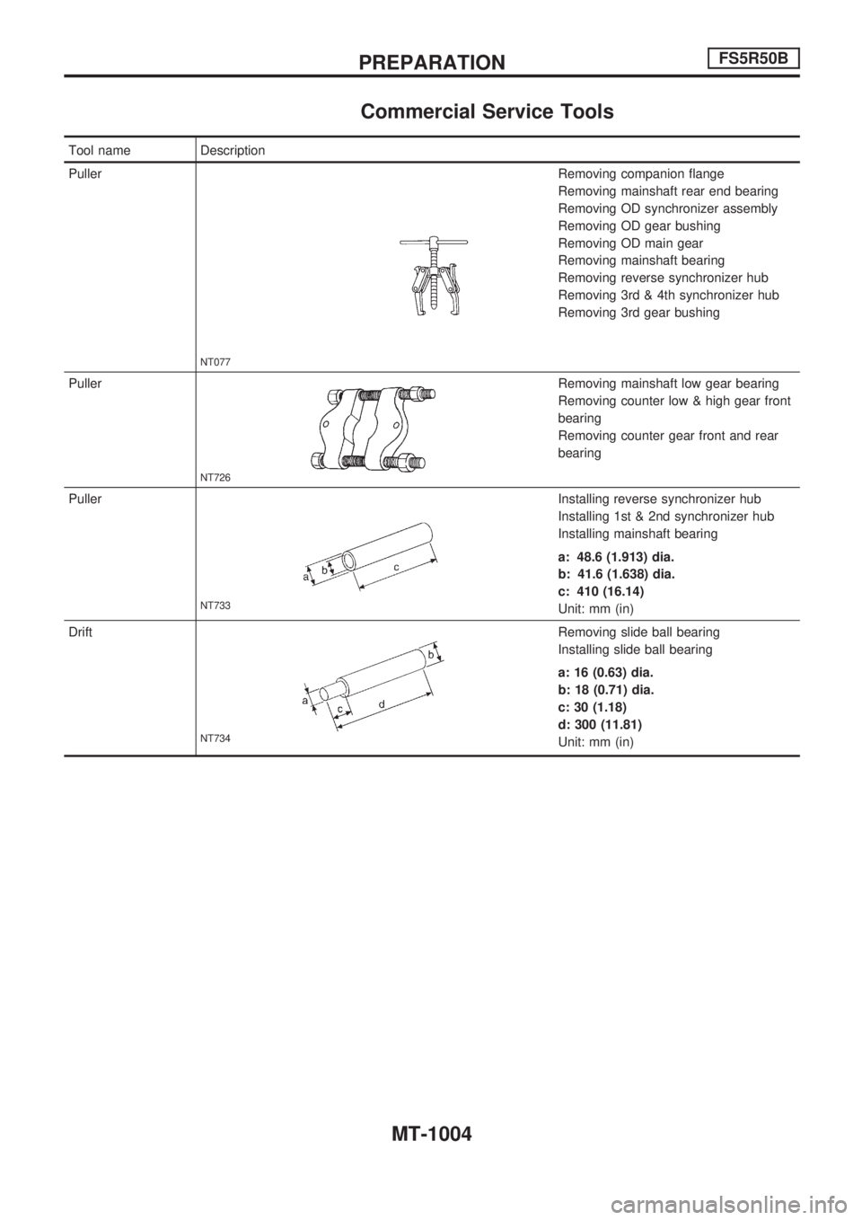
Commercial Service Tools
Tool name Description
Puller
NT077
Removing companion flange
Removing mainshaft rear end bearing
Removing OD synchronizer assembly
Removing OD gear bushing
Removing OD main gear
Removing mainshaft bearing
Removing reverse synchronizer hub
Removing 3rd & 4th synchronizer hub
Removing 3rd gear bushing
Puller
NT726
Removing mainshaft low gear bearing
Removing counter low & high gear front
bearing
Removing counter gear front and rear
bearing
Puller
NT733
Installing reverse synchronizer hub
Installing 1st & 2nd synchronizer hub
Installing mainshaft bearing
a: 48.6 (1.913) dia.
b: 41.6 (1.638) dia.
c: 410 (16.14)
Unit: mm (in)
Drift
NT734
Removing slide ball bearing
Installing slide ball bearing
a: 16 (0.63) dia.
b: 18 (0.71) dia.
c: 30 (1.18)
d: 300 (11.81)
Unit: mm (in)
PREPARATIONFS5R50B
MT-1004
Page 925 of 1033
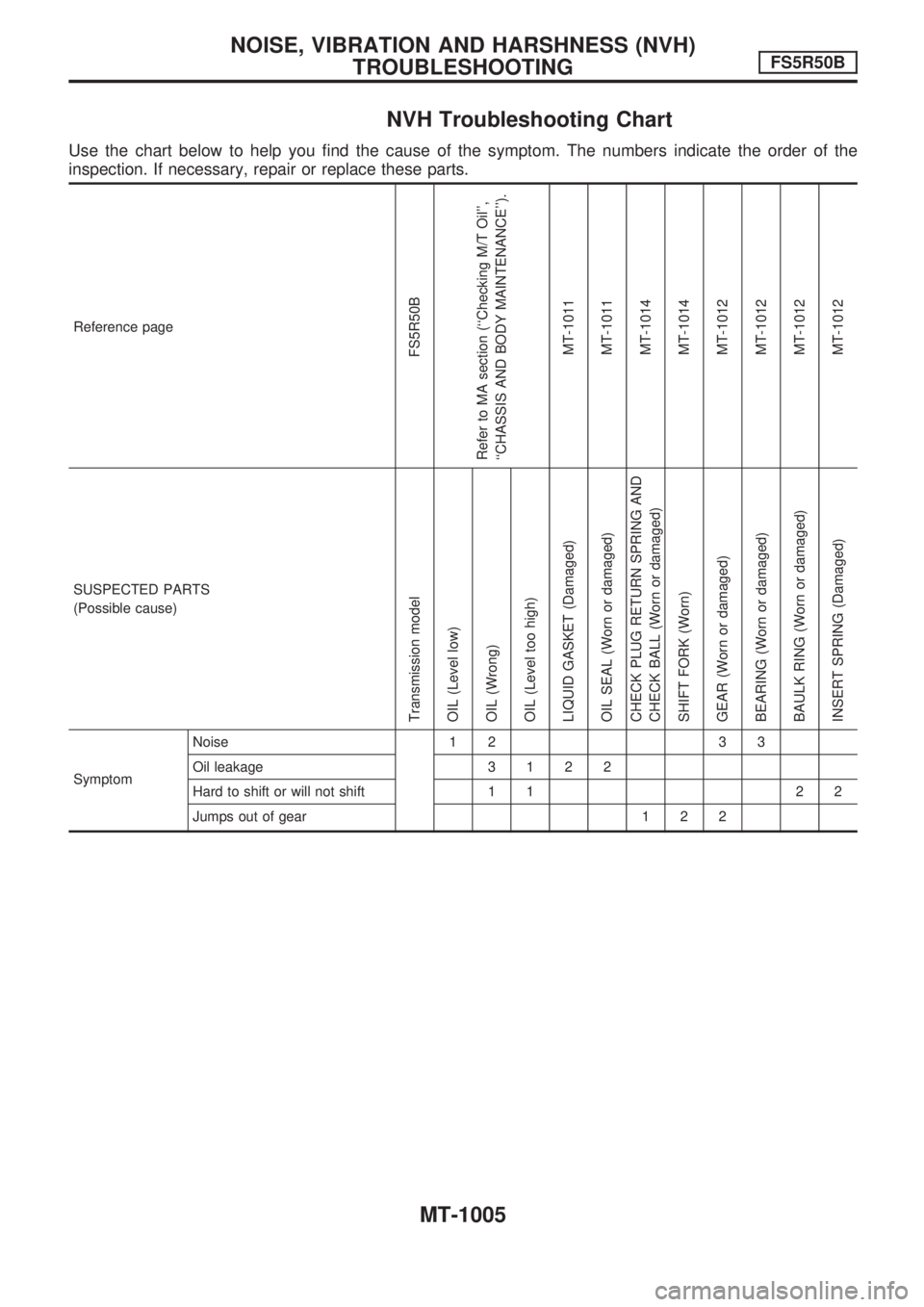
NVH Troubleshooting Chart
Use the chart below to help you find the cause of the symptom. The numbers indicate the order of the
inspection. If necessary, repair or replace these parts.
Reference page
FS5R50B
Refer to MA section (``Checking M/T Oil'',
``CHASSIS AND BODY MAINTENANCE'').
MT-1011
MT-1011
MT-1014
MT-1014
MT-1012
MT-1012
MT-1012
MT-1012
SUSPECTED PARTS
(Possible cause)
Transmission model
OIL (Level low)
OIL (Wrong)
OIL (Level too high)
LIQUID GASKET (Damaged)
OIL SEAL (Worn or damaged)
CHECK PLUG RETURN SPRING AND
CHECK BALL (Worn or damaged)
SHIFT FORK (Worn)
GEAR (Worn or damaged)
BEARING (Worn or damaged)
BAULK RING (Worn or damaged)
INSERT SPRING (Damaged)
SymptomNoise 1 2 3 3
Oil leakage3122
Hard to shift or will not shift 1 1 2 2
Jumps out of gear 1 2 2
NOISE, VIBRATION AND HARSHNESS (NVH)
TROUBLESHOOTINGFS5R50B
MT-1005
Page 926 of 1033
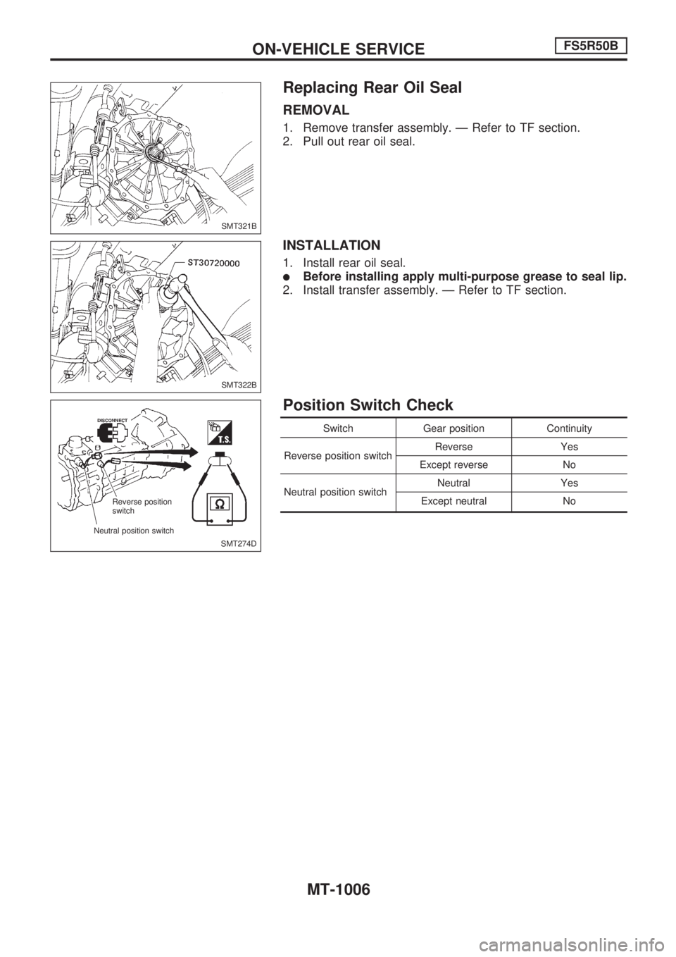
Replacing Rear Oil Seal
REMOVAL
1. Remove transfer assembly. Ð Refer to TF section.
2. Pull out rear oil seal.
INSTALLATION
1. Install rear oil seal.
lBefore installing apply multi-purpose grease to seal lip.
2. Install transfer assembly. Ð Refer to TF section.
Position Switch Check
Switch Gear position Continuity
Reverse position switchReverse Yes
Except reverse No
Neutral position switchNeutral Yes
Except neutral No
SMT321B
SMT322B
SMT274D Reverse position
switch
Neutral position switch
ON-VEHICLE SERVICEFS5R50B
MT-1006
Page 927 of 1033
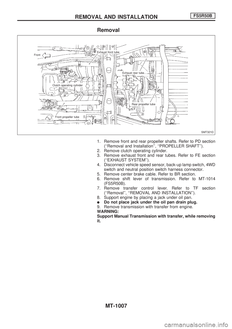
Removal
1. Remove front and rear propeller shafts. Refer to PD section
(``Removal and Installation'', ``PROPELLER SHAFT'').
2. Remove clutch operating cylinder.
3. Remove exhaust front and rear tubes. Refer to FE section
(``EXHAUST SYSTEM'').
4. Disconnect vehicle speed sensor, back-up lamp switch, 4WD
switch and neutral position switch harness connector.
5. Remove center brake cable. Refer to BR section.
6. Remove shift lever of transmission. Refer to MT-1014
(FS5R50B).
7. Remove transfer control lever. Refer to TF section
(``Removal'', ``REMOVAL AND INSTALLATION'').
8. Support engine by placing a jack under oil pan.
lDo not place jack under the oil pan drain plug.
9. Remove transmission with transfer from engine.
WARNING:
Support Manual Transmission with transfer, while removing
it.
SMT321D Exhaust front tube
Front
Exhaust rear tube
Clutch operating cylinder
Rear propeller tube
Front propeller tube
REMOVAL AND INSTALLATIONFS5R50B
MT-1007
Page 928 of 1033
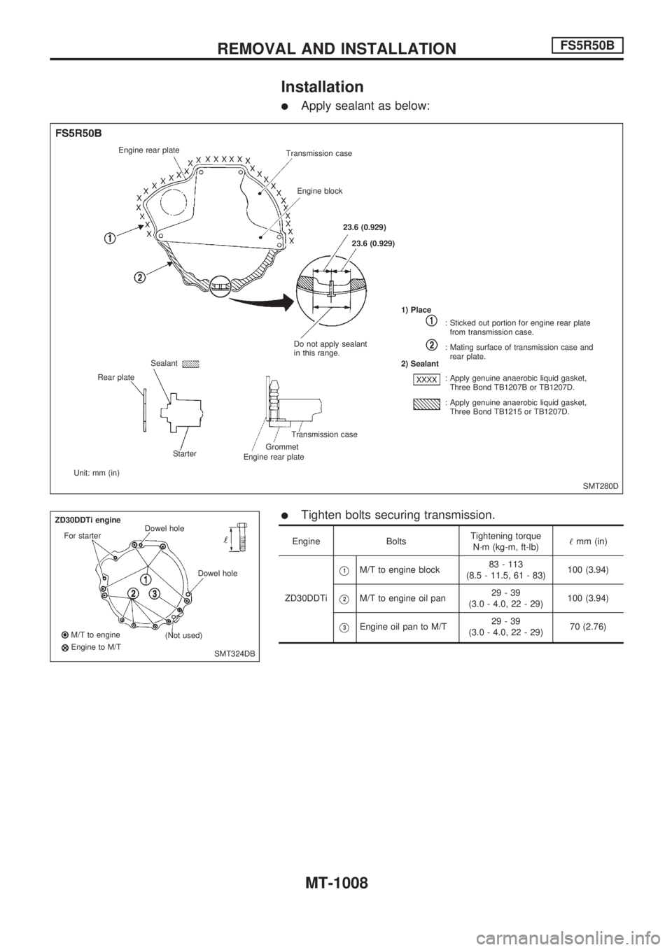
Installation
lApply sealant as below:
lTighten bolts securing transmission.
Engine BoltsTightening torque
N´m (kg-m, ft-lb)!mm (in)
ZD30DDTi
V1M/T to engine block83 - 113
(8.5 - 11.5, 61 - 83)100 (3.94)
V2M/T to engine oil pan29-39
(3.0 - 4.0, 22 - 29)100 (3.94)
V3Engine oil pan to M/T29-39
(3.0 - 4.0, 22 - 29)70 (2.76)
SMT280D Engine rear plate
Transmission case
Engine block
23.6 (0.929)
23.6 (0.929)
Do not apply sealant
in this range.1) Place
2) Sealant
: Sticked out portion for engine rear plate
from transmission case.
: Mating surface of transmission case and
rear plate.
: Apply genuine anaerobic liquid gasket,
Three Bond TB1207B or TB1207D.
: Apply genuine anaerobic liquid gasket,
Three Bond TB1215 or TB1207D.
Transmission case
Grommet
Engine rear plate Starter Sealant
Rear plate
Unit: mm (in)
SMT324DB ZD30DDTi engine
For starterDowel hole
Dowel hole
(Not used) M/T to engine
Engine to M/T
REMOVAL AND INSTALLATIONFS5R50B
MT-1008
Page 929 of 1033
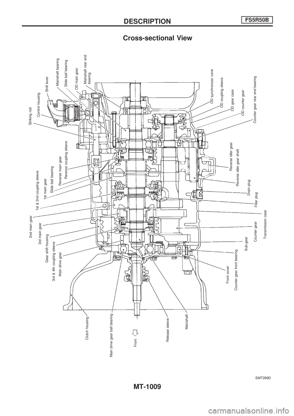
Cross-sectional View
SMT269D
Front Main drive gear ball bearingClutch housingMain drive gear 3rd & 4th coupling sleeveGear shift housing3rd main gear2nd main gear
1st & 2nd coupling sleeve
1st main gear
Slide ball bearing
Reverse main gear
Reverse coupling sleeveStriking rod
Control housing
Shift lever
Mainshaft bearing
Slide ball bearing
OD main gear
Mainshaft rear end
bearing
OD synchronizer cone
OD coupling sleeve
OD gear case
OD counter gear
Counter gear rear end bearing Reverse idler gear
Reverse idler gear shaft
Drain plug
Filler plug
Transmission case Counter gear Sub-gear Counter gear front bearingFront cover Mainshaft Release sleeve
DESCRIPTIONFS5R50B
MT-1009
Page 930 of 1033
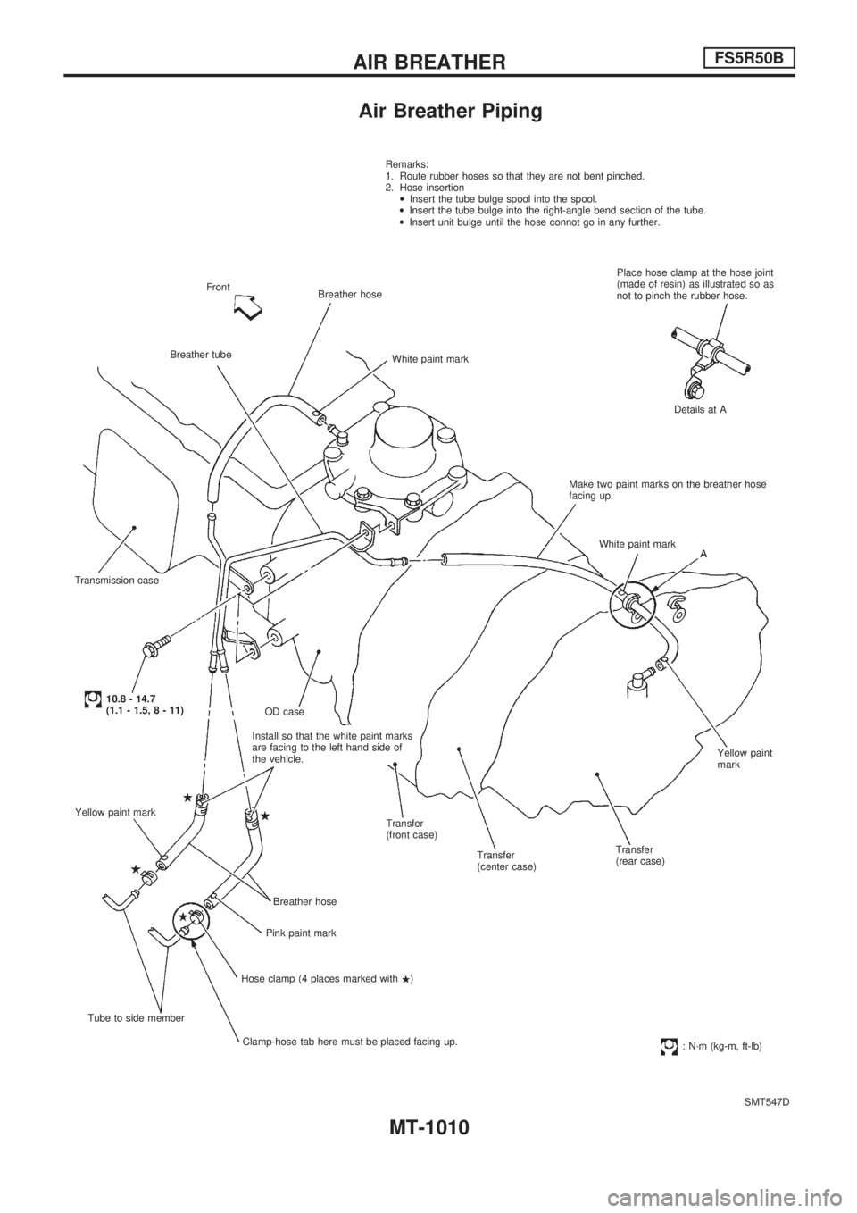
Air Breather Piping
SMT547D Remarks:
1. Route rubber hoses so that they are not bent pinched.
2. Hose insertion
·Insert the tube bulge spool into the spool.
·Insert the tube bulge into the right-angle bend section of the tube.
·Insert unit bulge until the hose connot go in any further.
Place hose clamp at the hose joint
(made of resin) as illustrated so as
not to pinch the rubber hose.
Details at A
Make two paint marks on the breather hose
facing up.
White paint mark
Yellow paint
mark
Transfer
(rear case) Transfer
(center case) Transfer
(front case) Install so that the white paint marks
are facing to the left hand side of
the vehicle.OD case
Breather hose
Pink paint mark
Hose clamp (4 places marked with.)
Clamp-hose tab here must be placed facing up. Tube to side member Yellow paint mark
10.8 - 14.7
(1.1 - 1.5, 8 - 11) Transmission caseBreather tubeFront
Breather hose
White paint mark
: N´m (kg-m, ft-lb)
AIR BREATHERFS5R50B
MT-1010