NISSAN PATROL 2000 Electronic Repair Manual
Manufacturer: NISSAN, Model Year: 2000, Model line: PATROL, Model: NISSAN PATROL 2000Pages: 1033, PDF Size: 30.71 MB
Page 911 of 1033
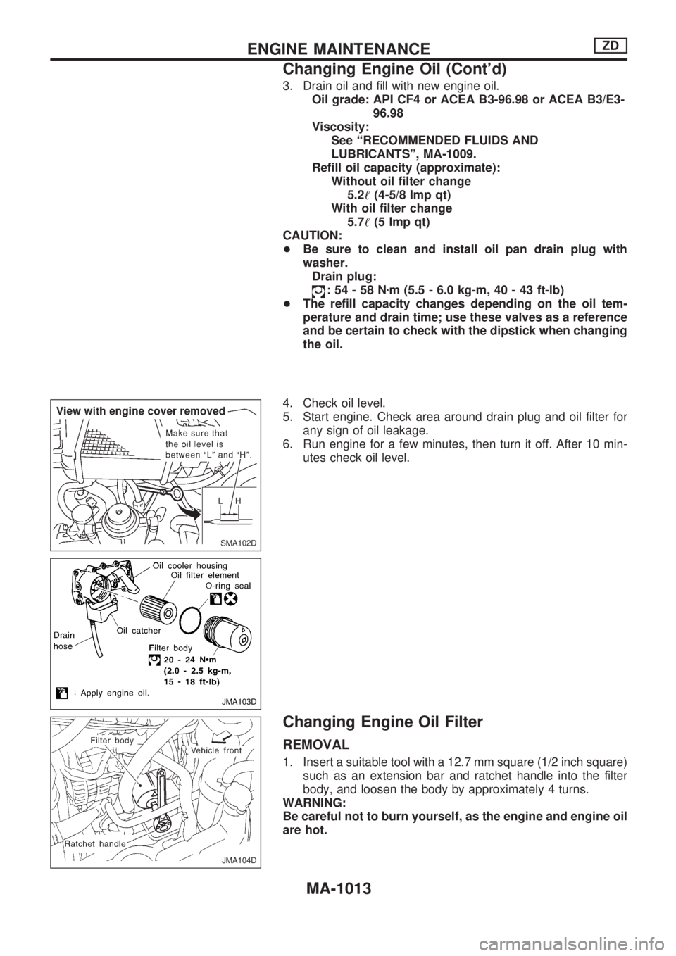
3. Drain oil and fill with new engine oil.
Oil grade: API CF4 or ACEA B3-96.98 or ACEA B3/E3-
96.98
Viscosity:
See ªRECOMMENDED FLUIDS AND
LUBRICANTSº, MA-1009.
Refill oil capacity (approximate):
Without oil filter change
5.2!(4-5/8 Imp qt)
With oil filter change
5.7!(5 Imp qt)
CAUTION:
+Be sure to clean and install oil pan drain plug with
washer.
Drain plug:
:54-58Nzm (5.5 - 6.0 kg-m, 40 - 43 ft-lb)
+The refill capacity changes depending on the oil tem-
perature and drain time; use these valves as a reference
and be certain to check with the dipstick when changing
the oil.
4. Check oil level.
5. Start engine. Check area around drain plug and oil filter for
any sign of oil leakage.
6. Run engine for a few minutes, then turn it off. After 10 min-
utes check oil level.
Changing Engine Oil Filter
REMOVAL
1. Insert a suitable tool with a 12.7 mm square (1/2 inch square)
such as an extension bar and ratchet handle into the filter
body, and loosen the body by approximately 4 turns.
WARNING:
Be careful not to burn yourself, as the engine and engine oil
are hot.
SMA102D
JMA103D
JMA104D
ENGINE MAINTENANCEZD
Changing Engine Oil (Cont'd)
MA-1013
Page 912 of 1033
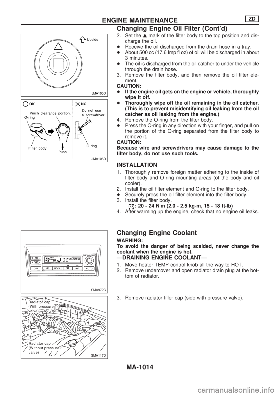
2. Set themmark of the filter body to the top position and dis-
charge the oil.
+Receive the oil discharged from the drain hose in a tray.
+About 500 cc (17.6 Imp fl oz) of oil will be discharged in about
3 minutes.
+The oil is discharged from the oil catcher to under the vehicle
through the drain hose.
3. Remove the filter body, and then remove the oil filter ele-
ment.
CAUTION:
+If the engine oil gets on the engine or vehicle, thoroughly
wipe it off.
+Thoroughly wipe off the oil remaining in the oil catcher.
(This is to prevent misidentifying oil leaking from the oil
catcher as oil leaking from the engine.)
4. Remove the O-ring from the filter body.
+Press the O-ring in any direction with your finger, and pull on
the portion of the O-ring separated from the filter body to
remove it.
CAUTION:
Because wire and screwdrivers may cause damage to the
filter body, do not use such tools.
INSTALLATION
1. Thoroughly remove foreign matter adhering to the inside of
filter body and O-ring mounting areas (of the body and oil
cooler).
2. Install the oil filter element and O-ring to the filter body.
+Securely press the oil filter element into the filter body.
3. Install the filter body.
:20-24Nzm (2.0 - 2.5 kg-m, 15 - 18 ft-lb)
4. After warming up the engine, check that no engine oil leaks.
Changing Engine Coolant
WARNING:
To avoid the danger of being scalded, never change the
coolant when the engine is hot.
ÐDRAINING ENGINE COOLANTÐ
1. Move heater TEMP control knob all the way to HOT.
2. Remove undercover and open radiator drain plug at the bot-
tom of radiator.
3. Remove radiator filler cap (side with pressure valve).
JMA105D
JMA106D
SMA972C
SMA117D
ENGINE MAINTENANCEZD
Changing Engine Oil Filter (Cont'd)
MA-1014
Page 913 of 1033
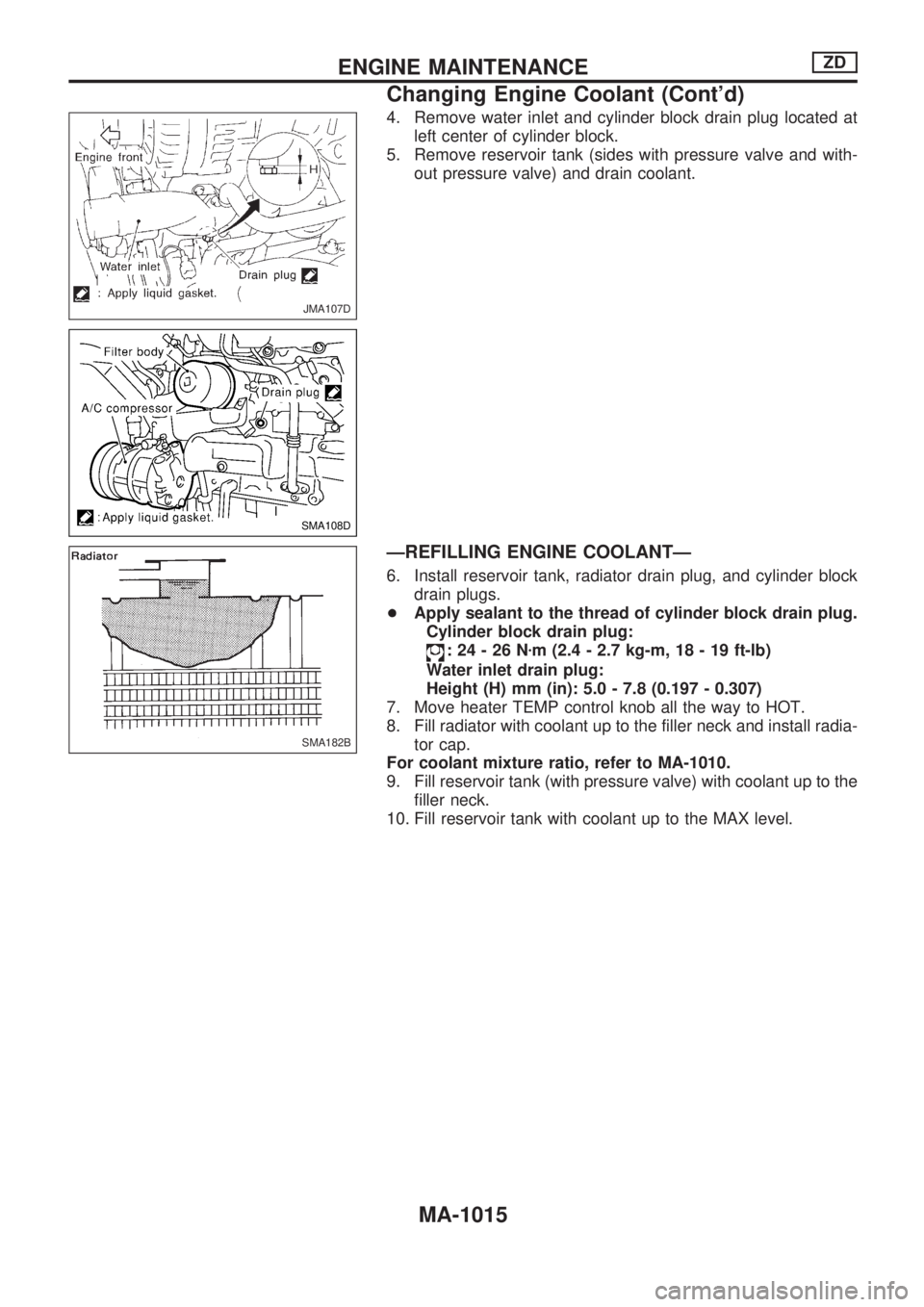
4. Remove water inlet and cylinder block drain plug located at
left center of cylinder block.
5. Remove reservoir tank (sides with pressure valve and with-
out pressure valve) and drain coolant.
ÐREFILLING ENGINE COOLANTÐ
6. Install reservoir tank, radiator drain plug, and cylinder block
drain plugs.
+Apply sealant to the thread of cylinder block drain plug.
Cylinder block drain plug:
:24-26Nzm (2.4 - 2.7 kg-m, 18 - 19 ft-lb)
Water inlet drain plug:
Height (H) mm (in): 5.0 - 7.8 (0.197 - 0.307)
7. Move heater TEMP control knob all the way to HOT.
8. Fill radiator with coolant up to the filler neck and install radia-
tor cap.
For coolant mixture ratio, refer to MA-1010.
9. Fill reservoir tank (with pressure valve) with coolant up to the
filler neck.
10. Fill reservoir tank with coolant up to the MAX level.
JMA107D
SMA108D
SMA182B
ENGINE MAINTENANCEZD
Changing Engine Coolant (Cont'd)
MA-1015
Page 914 of 1033
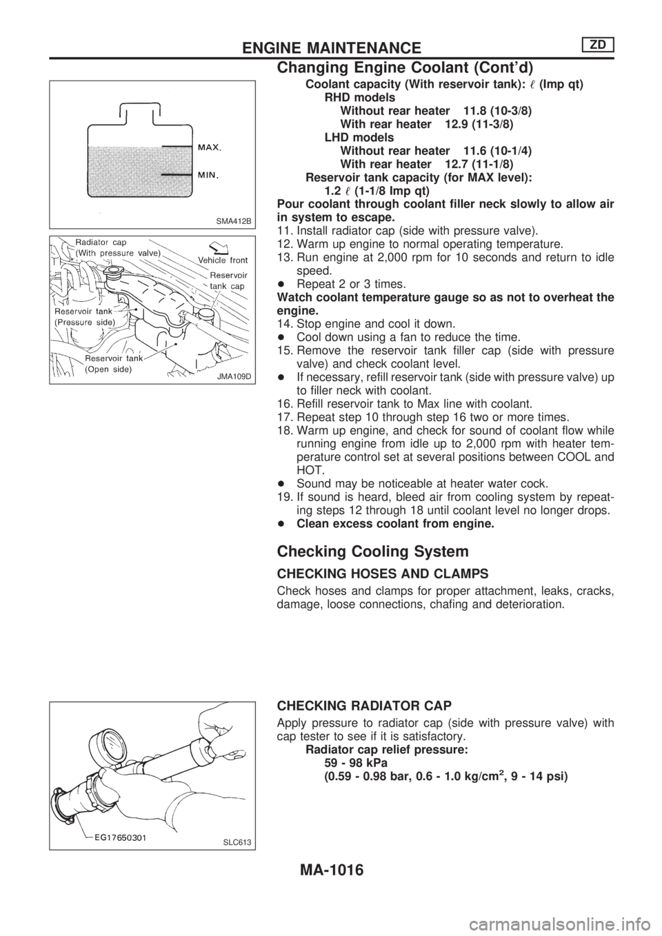
Coolant capacity (With reservoir tank):!(Imp qt)
RHD models
Without rear heater 11.8 (10-3/8)
With rear heater 12.9 (11-3/8)
LHD models
Without rear heater 11.6 (10-1/4)
With rear heater 12.7 (11-1/8)
Reservoir tank capacity (for MAX level):
1.2!(1-1/8 Imp qt)
Pour coolant through coolant filler neck slowly to allow air
in system to escape.
11. Install radiator cap (side with pressure valve).
12. Warm up engine to normal operating temperature.
13. Run engine at 2,000 rpm for 10 seconds and return to idle
speed.
+Repeat 2 or 3 times.
Watch coolant temperature gauge so as not to overheat the
engine.
14. Stop engine and cool it down.
+Cool down using a fan to reduce the time.
15. Remove the reservoir tank filler cap (side with pressure
valve) and check coolant level.
+If necessary, refill reservoir tank (side with pressure valve) up
to filler neck with coolant.
16. Refill reservoir tank to Max line with coolant.
17. Repeat step 10 through step 16 two or more times.
18. Warm up engine, and check for sound of coolant flow while
running engine from idle up to 2,000 rpm with heater tem-
perature control set at several positions between COOL and
HOT.
+Sound may be noticeable at heater water cock.
19. If sound is heard, bleed air from cooling system by repeat-
ing steps 12 through 18 until coolant level no longer drops.
+Clean excess coolant from engine.
Checking Cooling System
CHECKING HOSES AND CLAMPS
Check hoses and clamps for proper attachment, leaks, cracks,
damage, loose connections, chafing and deterioration.
CHECKING RADIATOR CAP
Apply pressure to radiator cap (side with pressure valve) with
cap tester to see if it is satisfactory.
Radiator cap relief pressure:
59-98kPa
(0.59 - 0.98 bar, 0.6 - 1.0 kg/cm
2,9-14psi)
SMA412B
JMA109D
SLC613
ENGINE MAINTENANCEZD
Changing Engine Coolant (Cont'd)
MA-1016
Page 915 of 1033
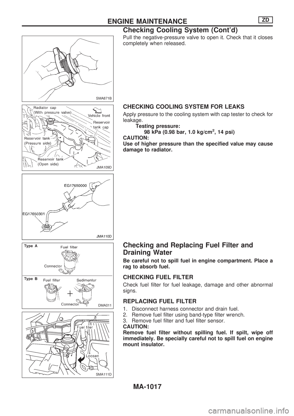
Pull the negative-pressure valve to open it. Check that it closes
completely when released.
CHECKING COOLING SYSTEM FOR LEAKS
Apply pressure to the cooling system with cap tester to check for
leakage.
Testing pressure:
98 kPa (0.98 bar, 1.0 kg/cm
2, 14 psi)
CAUTION:
Use of higher pressure than the specified value may cause
damage to radiator.
Checking and Replacing Fuel Filter and
Draining Water
Be careful not to spill fuel in engine compartment. Place a
rag to absorb fuel.
CHECKING FUEL FILTER
Check fuel filter for fuel leakage, damage and other abnormal
signs.
REPLACING FUEL FILTER
1. Disconnect harness connector and drain fuel.
2. Remove fuel filter using band-type filter wrench.
3. Remove fuel filter and fuel filter sensor.
CAUTION:
Remove fuel filter without spilling fuel. If spilt, wipe off
immediately. Be specially careful not to spill fuel on engine
mount insulator.
SMA871B
JMA109D
JMA110D
DMA011
SMA111D
ENGINE MAINTENANCEZD
Checking Cooling System (Cont'd)
MA-1017
Page 916 of 1033
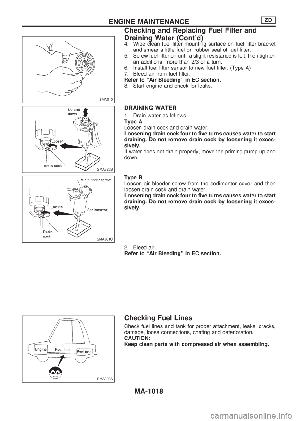
4. Wipe clean fuel filter mounting surface on fuel filter bracket
and smear a little fuel on rubber seal of fuel filter.
5. Screw fuel filter on until a slight resistance is felt, then tighten
an additional more than 2/3 of a turn.
6. Install fuel filter sensor to new fuel filter. (Type A)
7. Bleed air from fuel filter.
Refer to ªAir Bleedingº in EC section.
8. Start engine and check for leaks.
DRAINING WATER
1. Drain water as follows.
Type A
Loosen drain cock and drain water.
Loosening drain cock four to five turns causes water to start
draining. Do not remove drain cock by loosening it exces-
sively.
If water does not drain properly, move the priming pump up and
down.
Type B
Loosen air bleeder screw from the sedimentor cover and then
loosen drain cock and drain water.
Loosening drain cock four to five turns causes water to start
draining. Do not remove drain cock by loosening it exces-
sively.
2. Bleed air.
Refer to ªAir Bleedingº in EC section.
Checking Fuel Lines
Check fuel lines and tank for proper attachment, leaks, cracks,
damage, loose connections, chafing and deterioration.
CAUTION:
Keep clean parts with compressed air when assembling.
SMA010
SMA825B
SMA281C
SMA803A
ENGINE MAINTENANCEZD
Checking and Replacing Fuel Filter and
Draining Water (Cont'd)
MA-1018
Page 917 of 1033
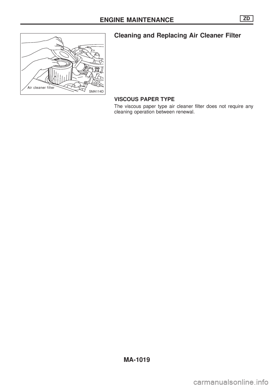
Cleaning and Replacing Air Cleaner Filter
VISCOUS PAPER TYPE
The viscous paper type air cleaner filter does not require any
cleaning operation between renewal.
SMA114D
ENGINE MAINTENANCEZD
MA-1019
Page 918 of 1033
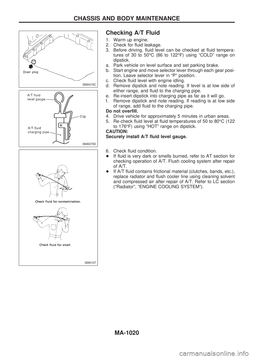
Checking A/T Fluid
1. Warm up engine.
2. Check for fluid leakage.
3. Before driving, fluid level can be checked at fluid tempera-
tures of 30 to 50ÉC (86 to 122ÉF) using ªCOLDº range on
dipstick.
a. Park vehicle on level surface and set parking brake.
b. Start engine and move selector lever through each gear posi-
tion. Leave selector lever in ªPº position.
c. Check fluid level with engine idling.
d. Remove dipstick and note reading. If level is at low side of
either range, and fluid to the charging pipe.
e. Re-insert dipstick into charging pipe as far as it will go.
f. Remove dipstick and note reading. If reading is at low side
of range, add fluid to the charging pipe.
Do not overfill.
4. Drive vehicle for approximately 5 minutes in urban areas.
5. Re-check fluid level at fluid temperatures of 50 to 80ÉC (122
to 176ÉF) using ªHOTº range on dipstick.
CAUTION:
Securely install A/T fluid level gauge.
6. Check fluid condition.
+If fluid is very dark or smells burned, refer to AT section for
checking operation of A/T. Flush cooling system after repair
of A/T.
+If A/T fluid contains frictional material (clutches, bands, etc.),
replace radiator and flush cooler line using cleaning solvent
and compressed air after repair of A/T. Refer to LC section
(ªRadiatorº, ªENGINE COOLING SYSTEMº).
SMA515C
SMA070D
SMA107
CHASSIS AND BODY MAINTENANCE
MA-1020
Page 919 of 1033
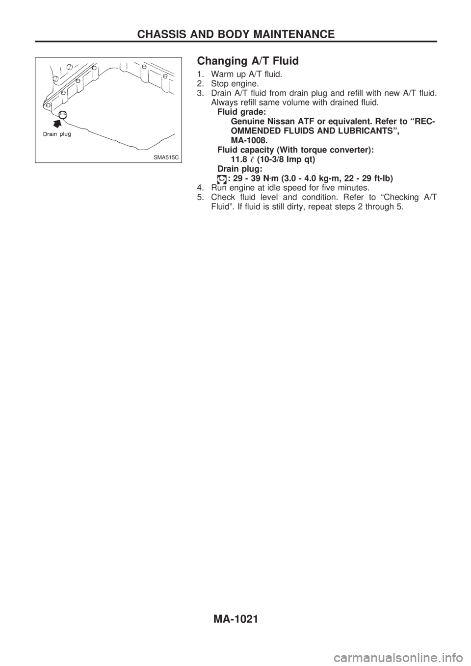
Changing A/T Fluid
1. Warm up A/T fluid.
2. Stop engine.
3. Drain A/T fluid from drain plug and refill with new A/T fluid.
Always refill same volume with drained fluid.
Fluid grade:
Genuine Nissan ATF or equivalent. Refer to ªREC-
OMMENDED FLUIDS AND LUBRICANTSº,
MA-1008.
Fluid capacity (With torque converter):
11.8!(10-3/8 Imp qt)
Drain plug:
:29-39Nzm (3.0 - 4.0 kg-m, 22 - 29 ft-lb)
4. Run engine at idle speed for five minutes.
5. Check fluid level and condition. Refer to ªChecking A/T
Fluidº. If fluid is still dirty, repeat steps 2 through 5.
SMA515C
CHASSIS AND BODY MAINTENANCE
MA-1021
Page 920 of 1033
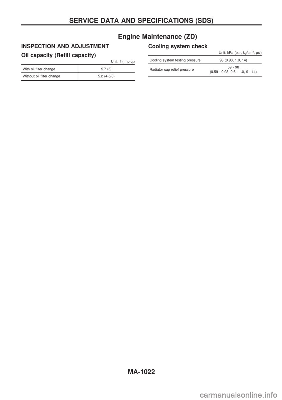
Engine Maintenance (ZD)
INSPECTION AND ADJUSTMENT
Oil capacity (Refill capacity)
Unit:!(Imp qt)
With oil filter change 5.7 (5)
Without oil filter change 5.2 (4-5/8)
Cooling system check
Unit: kPa (bar, kg/cm2, psi)
Cooling system testing pressure 98 (0.98, 1.0, 14)
Radiator cap relief pressure59-98
(0.59 - 0.98, 0.6 - 1.0,9-14)
SERVICE DATA AND SPECIFICATIONS (SDS)
MA-1022