NISSAN PATROL 2000 Electronic Repair Manual
Manufacturer: NISSAN, Model Year: 2000, Model line: PATROL, Model: NISSAN PATROL 2000Pages: 1033, PDF Size: 30.71 MB
Page 881 of 1033
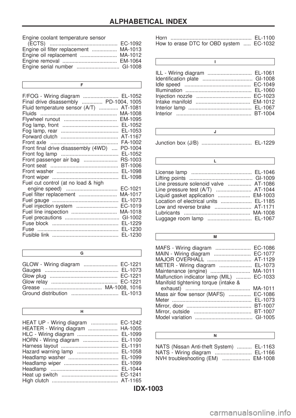
Engine coolant temperature sensor
(ECTS) .............................................. EC-1092
Engine oil filter replacement ................. MA-1013
Engine oil replacement ......................... MA-1012
Engine removal ..................................... EM-1064
Engine serial number ............................. GI-1008
F
F/FOG - Wiring diagram ........................ EL-1052
Final drive disassembly .............. PD-1004, 1005
Fluid temperature sensor (A/T) ............. AT-1081
Fluids .................................................... MA-1008
Flywheel runout .................................... EM-1095
Fog lamp, front ...................................... EL-1052
Fog lamp, rear ....................................... EL-1053
Forward clutch ....................................... AT-1167
Front axle .............................................. FA-1002
Front final drive disassembly (4WD) .... PD-1004
Front fog lamp ....................................... EL-1052
Front passenger air bag ....................... RS-1003
Front seat .............................................. BT-1006
Front washer .......................................... EL-1098
Front wiper ............................................. EL-1098
Fuel cut control (at no load & high
engine speed) ................................... EC-1021
Fuel filter replacement .......................... MA-1017
Fuel gauge ............................................. EL-1073
Fuel injection system ............................ EC-1019
Fuel line inspection ............................... MA-1018
Fuel precautions ..................................... GI-1002
Fuse block ............................................. EL-1229
Fuse ....................................................... EL-1230
Fusible link ............................................. EL-1230
G
GLOW - Wiring diagram ....................... EC-1221
Gauges .................................................. EL-1073
Glow plug .............................................. EC-1221
Glow relay ............................................. EC-1221
Grease ........................................ MA-1008, 1016
Ground distribution ................................ EL-1013
H
HEAT UP - Wiring diagram .................. EC-1242
HEATER - Wiring diagram .................... HA-1005
HLC - Wiring diagram ............................ EL-1099
HORN - Wiring diagram ........................ EL-1100
Harness layout ....................................... EL-1191
Hazard warning lamp ............................ EL-1058
Headlamp washer .................................. EL-1099
Headlamp wiper ..................................... EL-1099
Headlamp .............................................. EL-1044
Heat up switch ...................................... EC-1241
High clutch ............................................. AT-1165Horn ....................................................... EL-1100
How to erase DTC for OBD system ..... EC-1032
I
ILL - Wiring diagram .............................. EL-1061
Identification plate .................................. GI-1008
Idle speed ............................................. EC-1049
Illumination ............................................. EL-1060
Injection nozzle ..................................... EC-1023
Intake manifold ..................................... EM-1012
Interior lamp ........................................... EL-1067
Interior ................................................... BT-1004
J
Junction box (J/B) .................................. EL-1229
L
License lamp ......................................... EL-1046
Lifting points ........................................... GI-1009
Line pressure solenoid valve ................ AT-1086
Line pressure test (A/T) ........................ AT-1044
Liquid gasket application ...................... EM-1003
Location of electrical units ..................... EL-1185
Low and reverse brake ......................... AT-1171
Lubricants ............................................. MA-1008
Luggage room lamp .............................. EL-1067
M
MAFS - Wiring diagram ........................ EC-1086
MAIN - Wiring diagram ......................... EC-1077
MAJOR OVERHALL .............................. AT-1129
METER - Wiring diagram ...................... EL-1073
Maintenance (engine) ........................... MA-1011
Malfunction indicator lamp (MIL) .......... EC-1033
Manifold tightening torque (intake &
exhaust) ............................................ MA-1011
Mass air flow sensor (MAFS) ............... EC-1086
Meter ...................................................... EL-1073
Mirror, door ............................................ BT-1007
Mirror, outside ....................................... BT-1007
Model variation ....................................... GI-1005
N
NATS (Nissan Anti-theft System) .......... EL-1163
NATS - Wiring diagram ......................... EL-1166
NVH troubleshooting (EM) ................... EM-1008
ALPHABETICAL INDEX
IDX-1003
Page 882 of 1033
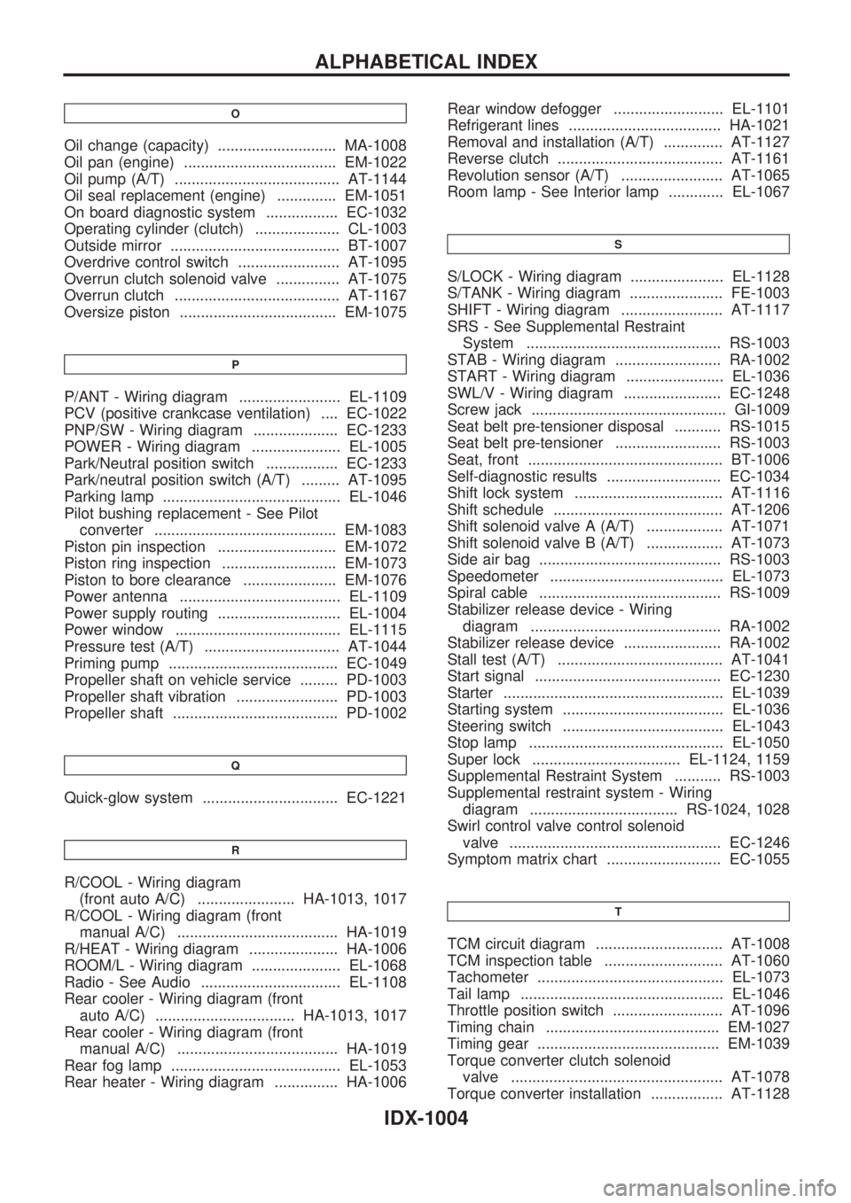
O
Oil change (capacity) ............................ MA-1008
Oil pan (engine) .................................... EM-1022
Oil pump (A/T) ....................................... AT-1144
Oil seal replacement (engine) .............. EM-1051
On board diagnostic system ................. EC-1032
Operating cylinder (clutch) .................... CL-1003
Outside mirror ........................................ BT-1007
Overdrive control switch ........................ AT-1095
Overrun clutch solenoid valve ............... AT-1075
Overrun clutch ....................................... AT-1167
Oversize piston ..................................... EM-1075
P
P/ANT - Wiring diagram ........................ EL-1109
PCV (positive crankcase ventilation) .... EC-1022
PNP/SW - Wiring diagram .................... EC-1233
POWER - Wiring diagram ..................... EL-1005
Park/Neutral position switch ................. EC-1233
Park/neutral position switch (A/T) ......... AT-1095
Parking lamp .......................................... EL-1046
Pilot bushing replacement - See Pilot
converter ........................................... EM-1083
Piston pin inspection ............................ EM-1072
Piston ring inspection ........................... EM-1073
Piston to bore clearance ...................... EM-1076
Power antenna ...................................... EL-1109
Power supply routing ............................. EL-1004
Power window ....................................... EL-1115
Pressure test (A/T) ................................ AT-1044
Priming pump ........................................ EC-1049
Propeller shaft on vehicle service ......... PD-1003
Propeller shaft vibration ........................ PD-1003
Propeller shaft ....................................... PD-1002
Q
Quick-glow system ................................ EC-1221
R
R/COOL - Wiring diagram
(front auto A/C) ....................... HA-1013, 1017
R/COOL - Wiring diagram (front
manual A/C) ...................................... HA-1019
R/HEAT - Wiring diagram ..................... HA-1006
ROOM/L - Wiring diagram ..................... EL-1068
Radio - See Audio ................................. EL-1108
Rear cooler - Wiring diagram (front
auto A/C) ................................. HA-1013, 1017
Rear cooler - Wiring diagram (front
manual A/C) ...................................... HA-1019
Rear fog lamp ........................................ EL-1053
Rear heater - Wiring diagram ............... HA-1006Rear window defogger .......................... EL-1101
Refrigerant lines .................................... HA-1021
Removal and installation (A/T) .............. AT-1127
Reverse clutch ....................................... AT-1161
Revolution sensor (A/T) ........................ AT-1065
Room lamp - See Interior lamp ............. EL-1067
S
S/LOCK - Wiring diagram ...................... EL-1128
S/TANK - Wiring diagram ...................... FE-1003
SHIFT - Wiring diagram ........................ AT-1117
SRS - See Supplemental Restraint
System .............................................. RS-1003
STAB - Wiring diagram ......................... RA-1002
START - Wiring diagram ....................... EL-1036
SWL/V - Wiring diagram ....................... EC-1248
Screw jack .............................................. GI-1009
Seat belt pre-tensioner disposal ........... RS-1015
Seat belt pre-tensioner ......................... RS-1003
Seat, front .............................................. BT-1006
Self-diagnostic results ........................... EC-1034
Shift lock system ................................... AT-1116
Shift schedule ........................................ AT-1206
Shift solenoid valve A (A/T) .................. AT-1071
Shift solenoid valve B (A/T) .................. AT-1073
Side air bag ........................................... RS-1003
Speedometer ......................................... EL-1073
Spiral cable ........................................... RS-1009
Stabilizer release device - Wiring
diagram ............................................. RA-1002
Stabilizer release device ....................... RA-1002
Stall test (A/T) ....................................... AT-1041
Start signal ............................................ EC-1230
Starter .................................................... EL-1039
Starting system ...................................... EL-1036
Steering switch ...................................... EL-1043
Stop lamp .............................................. EL-1050
Super lock ................................... EL-1124, 1159
Supplemental Restraint System ........... RS-1003
Supplemental restraint system - Wiring
diagram ................................... RS-1024, 1028
Swirl control valve control solenoid
valve .................................................. EC-1246
Symptom matrix chart ........................... EC-1055
T
TCM circuit diagram .............................. AT-1008
TCM inspection table ............................ AT-1060
Tachometer ............................................ EL-1073
Tail lamp ................................................ EL-1046
Throttle position switch .......................... AT-1096
Timing chain ......................................... EM-1027
Timing gear ........................................... EM-1039
Torque converter clutch solenoid
valve .................................................. AT-1078
Torque converter installation ................. AT-1128
ALPHABETICAL INDEX
IDX-1004
Page 883 of 1033
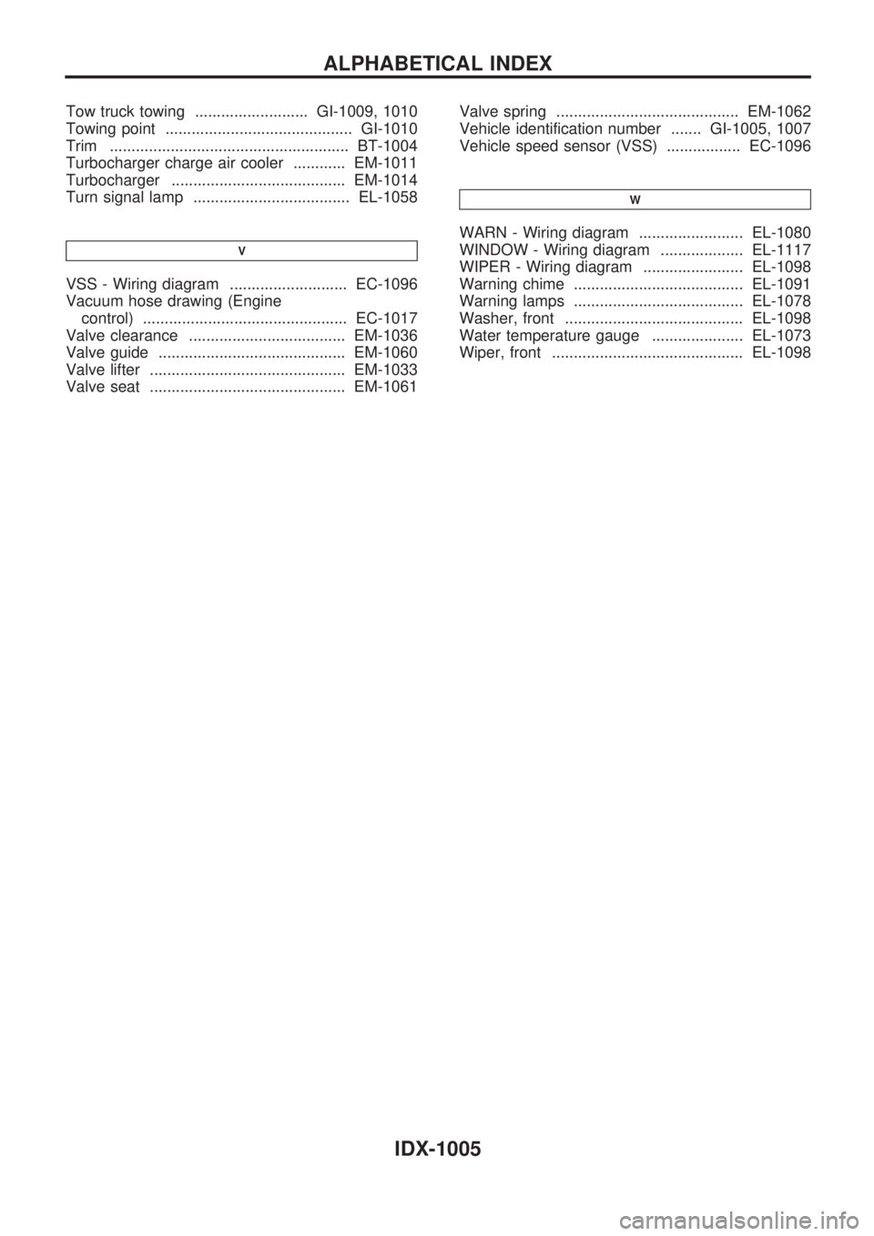
Tow truck towing .......................... GI-1009, 1010
Towing point ........................................... GI-1010
Trim ....................................................... BT-1004
Turbocharger charge air cooler ............ EM-1011
Turbocharger ........................................ EM-1014
Turn signal lamp .................................... EL-1058
V
VSS - Wiring diagram ........................... EC-1096
Vacuum hose drawing (Engine
control) ............................................... EC-1017
Valve clearance .................................... EM-1036
Valve guide ........................................... EM-1060
Valve lifter ............................................. EM-1033
Valve seat ............................................. EM-1061Valve spring .......................................... EM-1062
Vehicle identification number ....... GI-1005, 1007
Vehicle speed sensor (VSS) ................. EC-1096
W
WARN - Wiring diagram ........................ EL-1080
WINDOW - Wiring diagram ................... EL-1117
WIPER - Wiring diagram ....................... EL-1098
Warning chime ....................................... EL-1091
Warning lamps ....................................... EL-1078
Washer, front ......................................... EL-1098
Water temperature gauge ..................... EL-1073
Wiper, front ............................................ EL-1098
ALPHABETICAL INDEX
IDX-1005
Page 884 of 1033
ENGINE LUBRICATION &
COOLING SYSTEMS
SECTION
LC
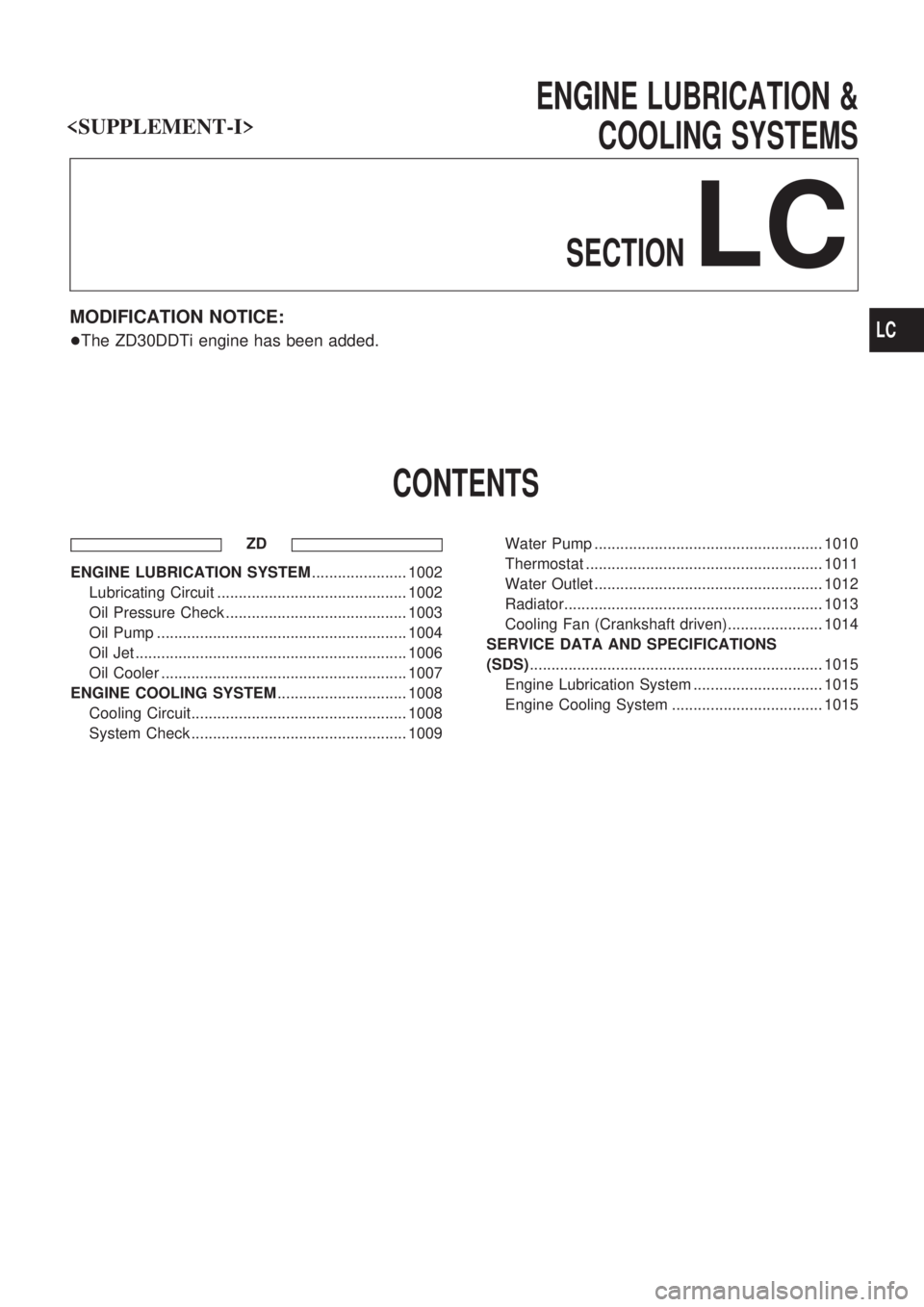
MODIFICATION NOTICE:
+The ZD30DDTi engine has been added.
CONTENTS
ZD
ENGINE LUBRICATION SYSTEM...................... 1002
Lubricating Circuit ............................................ 1002
Oil Pressure Check .......................................... 1003
Oil Pump .......................................................... 1004
Oil Jet ............................................................... 1006
Oil Cooler ......................................................... 1007
ENGINE COOLING SYSTEM.............................. 1008
Cooling Circuit.................................................. 1008
System Check .................................................. 1009Water Pump ..................................................... 1010
Thermostat ....................................................... 1011
Water Outlet ..................................................... 1012
Radiator............................................................ 1013
Cooling Fan (Crankshaft driven)...................... 1014
SERVICE DATA AND SPECIFICATIONS
(SDS).................................................................... 1015
Engine Lubrication System .............................. 1015
Engine Cooling System ................................... 1015
LC
Page 885 of 1033

Lubricating Circuit
SLC361B
ENGINE LUBRICATION SYSTEMZD
LC-1002
Page 886 of 1033
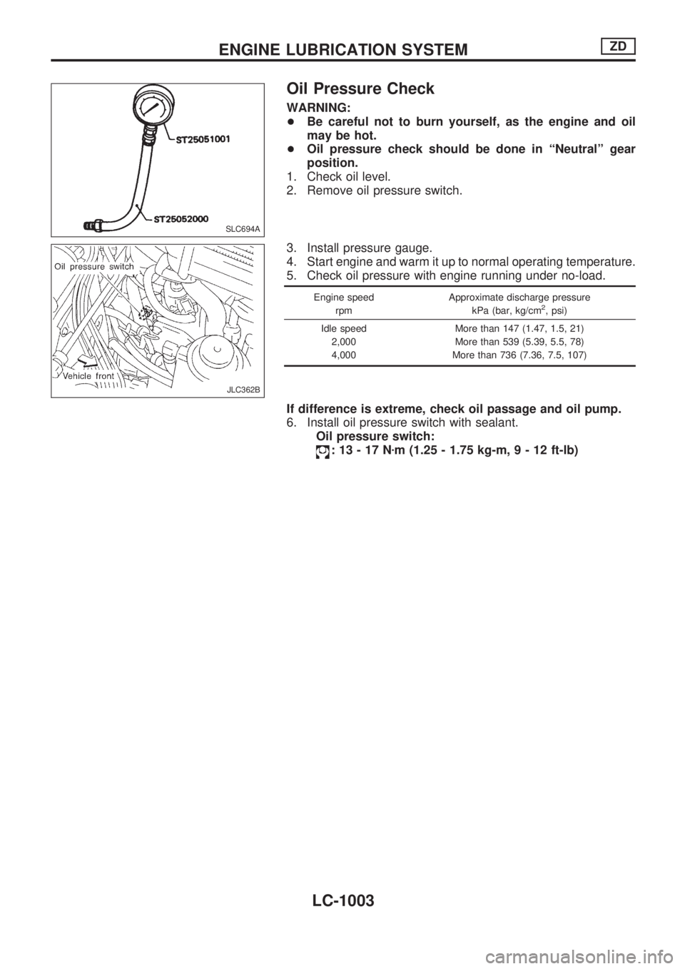
Oil Pressure Check
WARNING:
+Be careful not to burn yourself, as the engine and oil
may be hot.
+Oil pressure check should be done in ªNeutralº gear
position.
1. Check oil level.
2. Remove oil pressure switch.
3. Install pressure gauge.
4. Start engine and warm it up to normal operating temperature.
5. Check oil pressure with engine running under no-load.
Engine speed
rpmApproximate discharge pressure
kPa (bar, kg/cm2, psi)
Idle speed
2,000
4,000More than 147 (1.47, 1.5, 21)
More than 539 (5.39, 5.5, 78)
More than 736 (7.36, 7.5, 107)
If difference is extreme, check oil passage and oil pump.
6. Install oil pressure switch with sealant.
Oil pressure switch:
:13-17Nzm (1.25 - 1.75 kg-m,9-12ft-lb)
SLC694A
JLC362B
ENGINE LUBRICATION SYSTEMZD
LC-1003
Page 887 of 1033
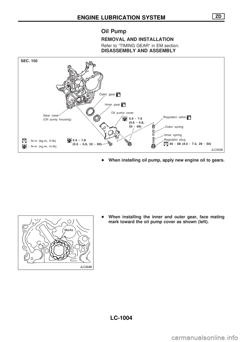
Oil Pump
REMOVAL AND INSTALLATION
Refer to ªTIMING GEARº in EM section.
DISASSEMBLY AND ASSEMBLY
+When installing oil pump, apply new engine oil to gears.
+When installing the inner and outer gear, face mating
mark toward the oil pump cover as shown (left).
JLC363B
JLC364B
ENGINE LUBRICATION SYSTEMZD
LC-1004
Page 888 of 1033
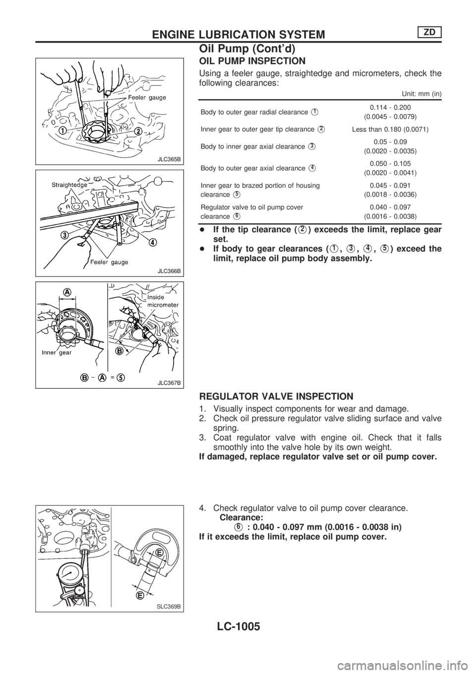
OIL PUMP INSPECTION
Using a feeler gauge, straightedge and micrometers, check the
following clearances:
Unit: mm (in)
Body to outer gear radial clearanceV10.114 - 0.200
(0.0045 - 0.0079)
Inner gear to outer gear tip clearance
V2Less than 0.180 (0.0071)
Body to inner gear axial clearance
V30.05 - 0.09
(0.0020 - 0.0035)
Body to outer gear axial clearance
V40.050 - 0.105
(0.0020 - 0.0041)
Inner gear to brazed portion of housing
clearance
V50.045 - 0.091
(0.0018 - 0.0036)
Regulator valve to oil pump cover
clearance
V60.040 - 0.097
(0.0016 - 0.0038)
+If the tip clearance (V2) exceeds the limit, replace gear
set.
+If body to gear clearances (
V1,V3,V4,V5) exceed the
limit, replace oil pump body assembly.
REGULATOR VALVE INSPECTION
1. Visually inspect components for wear and damage.
2. Check oil pressure regulator valve sliding surface and valve
spring.
3. Coat regulator valve with engine oil. Check that it falls
smoothly into the valve hole by its own weight.
If damaged, replace regulator valve set or oil pump cover.
4. Check regulator valve to oil pump cover clearance.
Clearance:
V6: 0.040 - 0.097 mm (0.0016 - 0.0038 in)
If it exceeds the limit, replace oil pump cover.
JLC365B
JLC366B
JLC367B
SLC369B
ENGINE LUBRICATION SYSTEMZD
Oil Pump (Cont'd)
LC-1005
Page 889 of 1033
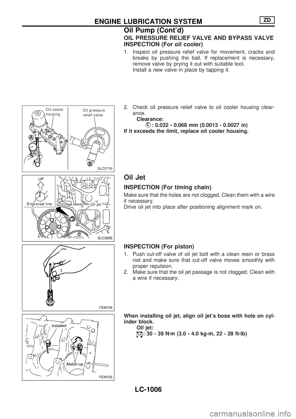
OIL PRESSURE RELIEF VALVE AND BYPASS VALVE
INSPECTION (For oil cooler)
1. Inspect oil pressure relief valve for movement, cracks and
breaks by pushing the ball. If replacement is necessary,
remove valve by prying it out with suitable tool.
Install a new valve in place by tapping it.
2. Check oil pressure relief valve to oil cooler housing clear-
ance.
Clearance:
VC: 0.032 - 0.068 mm (0.0013 - 0.0027 in)
If it exceeds the limit, replace oil cooler housing.
Oil Jet
INSPECTION (For timing chain)
Make sure that the holes are not clogged. Clean them with a wire
if necessary.
Drive oil jet into place after positioning alignment mark on.
INSPECTION (For piston)
1. Push cut-off valve of oil jet bolt with a clean resin or brass
rod and make sure that cut-off valve moves smoothly with
proper repulsion.
2. Make sure that the oil jet passage is not clogged. Clean with
a wire if necessary.
When installing oil jet, align oil jet's boss with hole on cyl-
inder block.
Oil jet:
:30-39Nzm (3.0 - 4.0 kg-m, 22 - 28 ft-lb)
SLC371B
SLC385B
FEM124
FEM125
ENGINE LUBRICATION SYSTEMZD
Oil Pump (Cont'd)
LC-1006
Page 890 of 1033
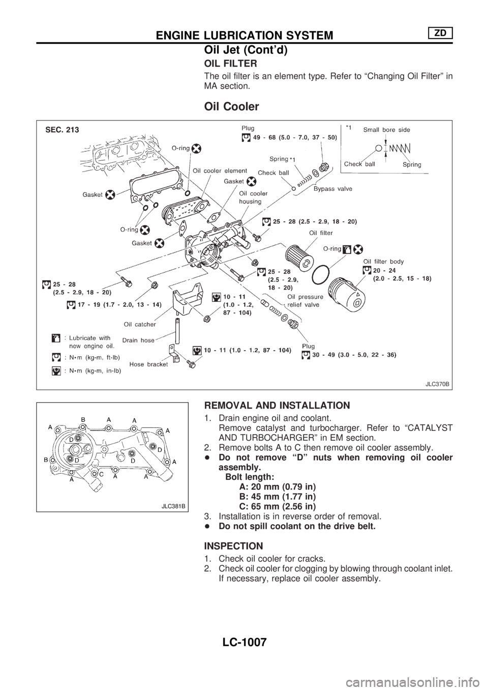
OIL FILTER
The oil filter is an element type. Refer to ªChanging Oil Filterº in
MA section.
Oil Cooler
REMOVAL AND INSTALLATION
1. Drain engine oil and coolant.
Remove catalyst and turbocharger. Refer to ªCATALYST
AND TURBOCHARGERº in EM section.
2. Remove bolts A to C then remove oil cooler assembly.
+Do not remove ªDº nuts when removing oil cooler
assembly.
Bolt length:
A: 20 mm (0.79 in)
B: 45 mm (1.77 in)
C: 65 mm (2.56 in)
3. Installation is in reverse order of removal.
+Do not spill coolant on the drive belt.
INSPECTION
1. Check oil cooler for cracks.
2. Check oil cooler for clogging by blowing through coolant inlet.
If necessary, replace oil cooler assembly.
JLC370B
JLC381B
ENGINE LUBRICATION SYSTEMZD
Oil Jet (Cont'd)
LC-1007