NISSAN PATROL 2000 Electronic Repair Manual
Manufacturer: NISSAN, Model Year: 2000, Model line: PATROL, Model: NISSAN PATROL 2000Pages: 1033, PDF Size: 30.71 MB
Page 951 of 1033
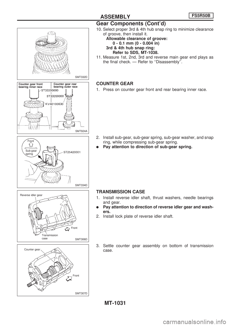
10. Select proper 3rd & 4th hub snap ring to minimize clearance
of groove, then install it.
Allowable clearance of groove:
0 - 0.1 mm (0 - 0.004 in)
3rd & 4th hub snap ring:
Refer to SDS, MT-1038.
11. Measure 1st, 2nd, 3rd and reverse main gear end plays as
the final check. Ð Refer to ``Disassembly''.
COUNTER GEAR
1. Press on counter gear front and rear bearing inner race.
2. Install sub-gear, sub-gear spring, sub-gear washer, and snap
ring, while compressing sub-gear spring.
lPay attention to direction of sub-gear spring.
TRANSMISSION CASE
1. Install reverse idler shaft, thrust washers, needle bearings
and gear.
lPay attention to direction of reverse idler gear and wash-
ers.
2. Install lock plate of reverse idler shaft.
3. Settle counter gear assembly on bottom of transmission
case.
SMT332D
SMT924A Counter gear front
bearing inner raceCounter gear rear
bearing outer race
SMT334D Front
Sub-gear
spring
SMT306D Reverse idler gear
Front
Transmission
case
SMT307D Counter gear
Front
ASSEMBLYFS5R50B
Gear Components (Cont'd)
MT-1031
Page 952 of 1033
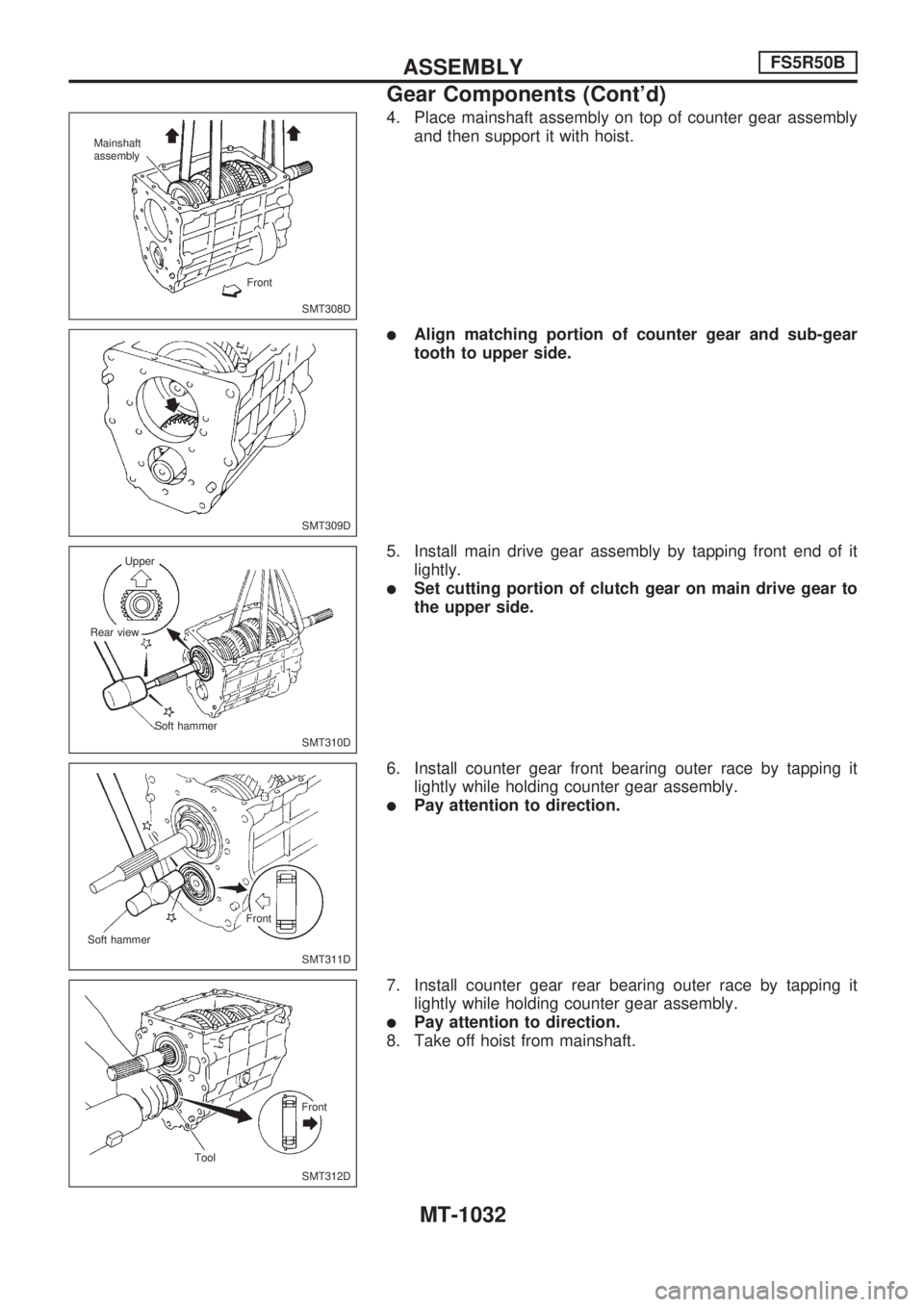
4. Place mainshaft assembly on top of counter gear assembly
and then support it with hoist.
lAlign matching portion of counter gear and sub-gear
tooth to upper side.
5. Install main drive gear assembly by tapping front end of it
lightly.
lSet cutting portion of clutch gear on main drive gear to
the upper side.
6. Install counter gear front bearing outer race by tapping it
lightly while holding counter gear assembly.
lPay attention to direction.
7. Install counter gear rear bearing outer race by tapping it
lightly while holding counter gear assembly.
lPay attention to direction.
8. Take off hoist from mainshaft.
SMT308D Mainshaft
assembly
Front
SMT309D
SMT310D Upper
Rear view
Soft hammer
SMT311D Front
Soft hammer
SMT312D Front
Tool
ASSEMBLYFS5R50B
Gear Components (Cont'd)
MT-1032
Page 953 of 1033
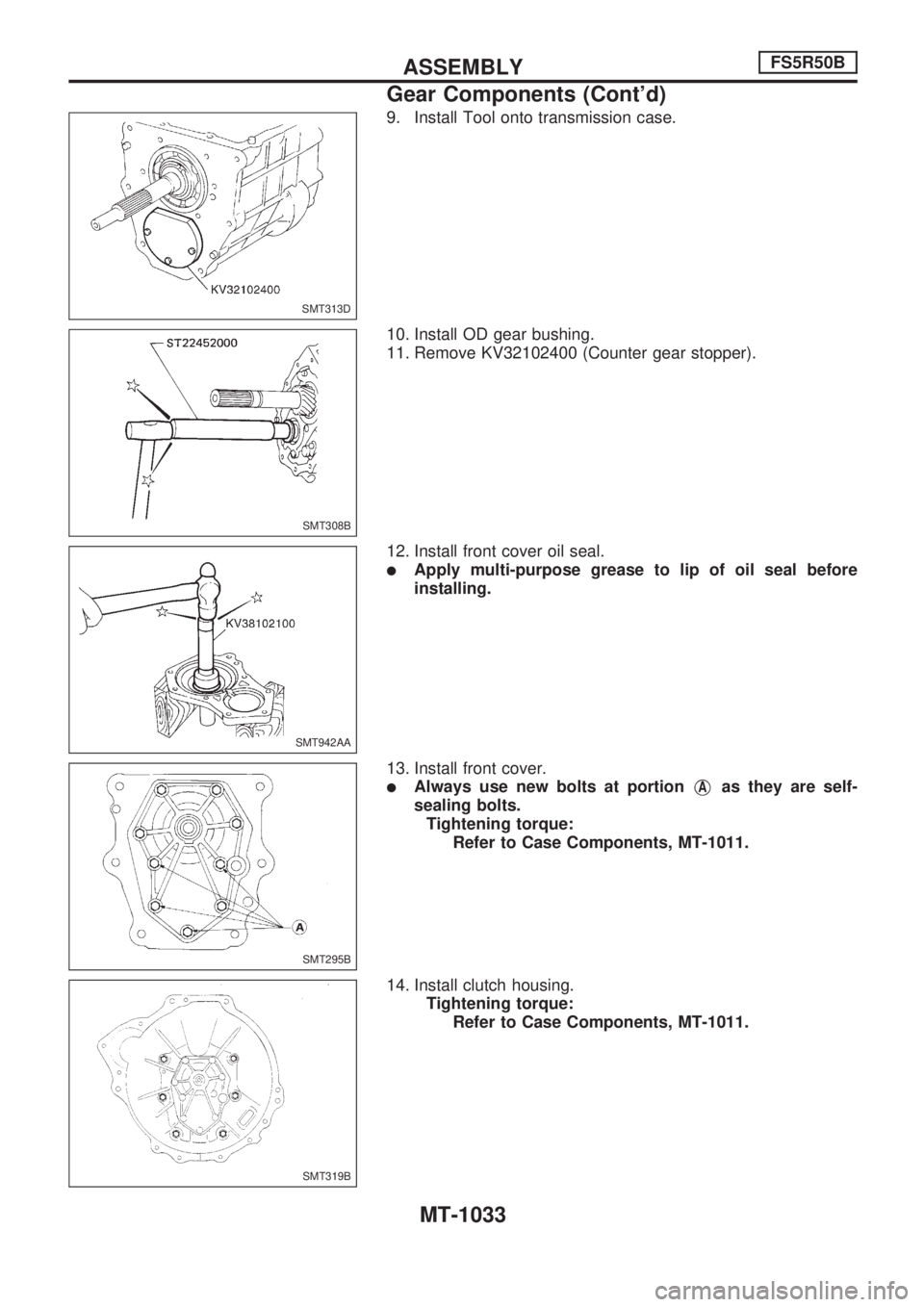
9. Install Tool onto transmission case.
10. Install OD gear bushing.
11. Remove KV32102400 (Counter gear stopper).
12. Install front cover oil seal.
lApply multi-purpose grease to lip of oil seal before
installing.
13. Install front cover.
lAlways use new bolts at portionVAas they are self-
sealing bolts.
Tightening torque:
Refer to Case Components, MT-1011.
14. Install clutch housing.
Tightening torque:
Refer to Case Components, MT-1011.
SMT313D
SMT308B
SMT942AA
SMT295B
SMT319B
ASSEMBLYFS5R50B
Gear Components (Cont'd)
MT-1033
Page 954 of 1033
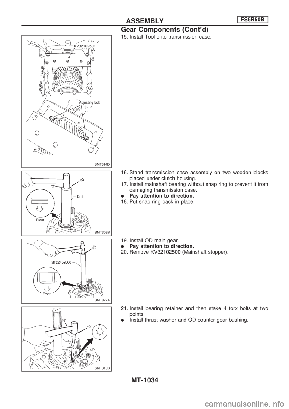
15. Install Tool onto transmission case.
16. Stand transmission case assembly on two wooden blocks
placed under clutch housing.
17. Install mainshaft bearing without snap ring to prevent it from
damaging transmission case.
lPay attention to direction.
18. Put snap ring back in place.
19. Install OD main gear.
lPay attention to direction.
20. Remove KV32102500 (Mainshaft stopper).
21. Install bearing retainer and then stake 4 torx bolts at two
points.
lInstall thrust washer and OD counter gear bushing.
SMT314D Adjusting bolt
SMT309B Drift
Front
SMT872A Front
SMT310B
ASSEMBLYFS5R50B
Gear Components (Cont'd)
MT-1034
Page 955 of 1033
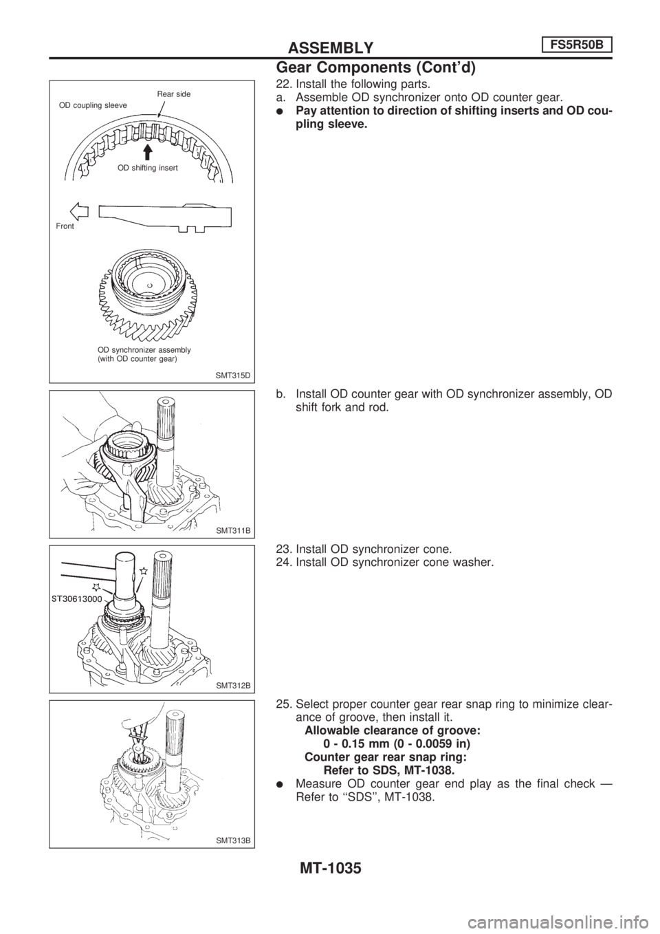
22. Install the following parts.
a. Assemble OD synchronizer onto OD counter gear.
lPay attention to direction of shifting inserts and OD cou-
pling sleeve.
b. Install OD counter gear with OD synchronizer assembly, OD
shift fork and rod.
23. Install OD synchronizer cone.
24. Install OD synchronizer cone washer.
25. Select proper counter gear rear snap ring to minimize clear-
ance of groove, then install it.
Allowable clearance of groove:
0 - 0.15 mm (0 - 0.0059 in)
Counter gear rear snap ring:
Refer to SDS, MT-1038.
lMeasure OD counter gear end play as the final check Ð
Refer to ``SDS'', MT-1038.
SMT315D Rear side
OD coupling sleeve
OD shifting insert
Front
OD synchronizer assembly
(with OD counter gear)
SMT311B
SMT312B
SMT313B
ASSEMBLYFS5R50B
Gear Components (Cont'd)
MT-1035
Page 956 of 1033
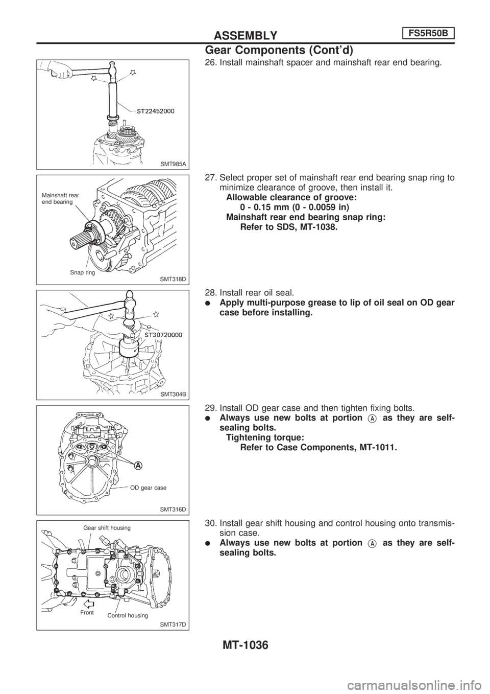
26. Install mainshaft spacer and mainshaft rear end bearing.
27. Select proper set of mainshaft rear end bearing snap ring to
minimize clearance of groove, then install it.
Allowable clearance of groove:
0 - 0.15 mm (0 - 0.0059 in)
Mainshaft rear end bearing snap ring:
Refer to SDS, MT-1038.
28. Install rear oil seal.
lApply multi-purpose grease to lip of oil seal on OD gear
case before installing.
29. Install OD gear case and then tighten fixing bolts.
lAlways use new bolts at portionVAas they are self-
sealing bolts.
Tightening torque:
Refer to Case Components, MT-1011.
30. Install gear shift housing and control housing onto transmis-
sion case.
lAlways use new bolts at portionVAas they are self-
sealing bolts.
SMT985A
SMT318D Mainshaft rear
end bearing
Snap ring
SMT304B
SMT316D OD gear case
SMT317D Gear shift housing
Control housing Front
ASSEMBLYFS5R50B
Gear Components (Cont'd)
MT-1036
Page 957 of 1033
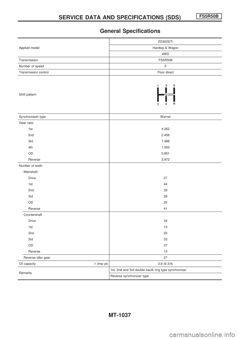
General Specifications
Applied modelZD30DDTi
Hardtop & Wagon
4WD
TransmissionFS5R50B
Number of speed5
Transmission controlFloor direct
Shift pattern
Synchromesh typeWarner
Gear ratio
1st4.262
2nd2.456
3rd1.488
4th1.000
OD0.851
Reverse3.972
Number of teeth
Mainshaft
Drive27
1st44
2nd39
3rd39
OD25
Reverse41
Countershaft
Drive34
1st13
2nd20
3rd33
OD37
Reverse13
Reverse idler gear27
Oil capacity!(Imp pt) 3.8 (6-3/4)
Remarks1st, 2nd and 3rd double baulk ring type synchronizer
Reverse synchronizer type
SERVICE DATA AND SPECIFICATIONS (SDS)FS5R50B
MT-1037
Page 958 of 1033
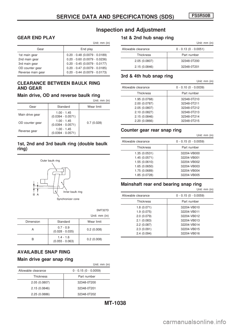
Inspection and Adjustment
GEAR END PLAY
Unit: mm (in)
Gear End play
1st main gear 0.20 - 0.48 (0.0079 - 0.0189)
2nd main gear 0.20 - 0.60 (0.0079 - 0.0236)
3rd main gear 0.20 - 0.45 (0.0079 - 0.0177)
OD counter gear 0.20 - 0.47 (0.0079 - 0.0185)
Reverse main gear 0.20 - 0.44 (0.0079 - 0.0173)
CLEARANCE BETWEEN BAULK RING
AND GEAR
Main drive, OD and reverse baulk ring
Unit: mm (in)
Gear Standard Wear limit
Main drive gear1.00 - 1.45
(0.0394 - 0.0571)
0.7 (0.028) OD counter gear1.00 - 1.45
(0.0394 - 0.0571)
Reverse gear1.00 - 1.45
(0.0394 - 0.0571)
1st, 2nd and 3rd baulk ring (double baulk
ring)
SMT327D Outer baulk ring
Inner baulk ring
Synchronizer cone
Unit: mm (in)
Dimension Standard Wear limit
A0.7 - 0.9
(0.028 - 0.035)0.2 (0.008)
B1.4 - 1.6
(0.055 - 0.063)0.2 (0.008)
AVAILABLE SNAP RING
Main drive gear snap ring
Unit: mm (in)
Allowable clearance 0 - 0.15 (0 - 0.0059)
Thickness Part number
2.05 (0.0807) 32348-0T200
2.15 (0.0846) 32348-0T201
2.25 (0.0886) 32348-0T202
1st & 2nd hub snap ring
Unit: mm (in)
Allowable clearance 0 - 0.13 (0 - 0.0051)
Thickness Part number
2.05 (0.0807) 32348-0T200
2.15 (0.0846) 32348-0T201
3rd & 4th hub snap ring
Unit: mm (in)
Allowable clearance 0 - 0.10 (0 - 0.0039)
Thickness Part number
1.95 (0.0768) 32348-0T210
2.00 (0.0787) 32348-0T211
2.05 (0.0807) 32348-0T212
2.10 (0.0827) 32348-0T213
2.15 (0.0846) 32348-0T214
2.20 (0.0866) 32348-0T215
Counter gear rear snap ring
Unit: mm (in)
Allowable clearance 0 - 0.15 (0 - 0.0059)
Thickness Part number
1.35 (0.0531) 32204-VB000
1.45 (0.0571) 32204-VB001
1.55 (0.0610) 32204-VB002
1.65 (0.0650) 32204-VB003
1.75 (0.0689) 32204-VB004
1.85 (0.0728) 32204-VB005
Mainshaft rear end bearing snap ring
Unit: mm (in)
Allowable clearance 0 - 0.15 (0 - 0.0059)
Thickness Part number
1.8 (0.071) 32204-VB010
1.9 (0.075) 32204-VB011
2.0 (0.079) 32204-VB012
2.1 (0.083) 32204-VB013
2.2 (0.087) 32204-VB014
2.3 (0.091) 32204-VB015
2.4 (0.094) 32204-VB016
SERVICE DATA AND SPECIFICATIONS (SDS)FS5R50B
MT-1038
Page 959 of 1033
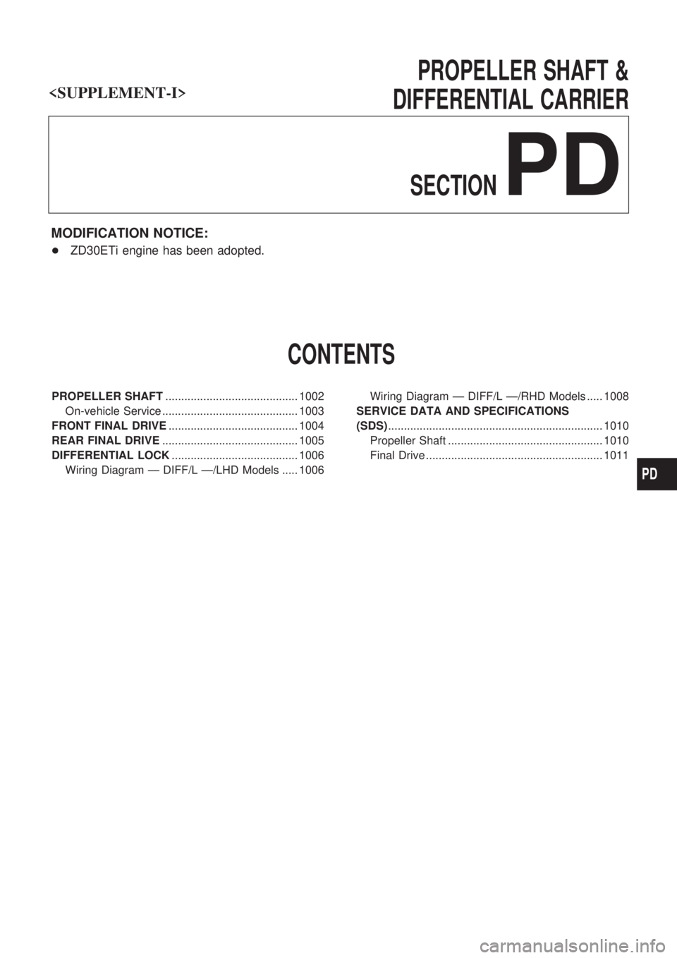
PROPELLER SHAFT &
DIFFERENTIAL CARRIER
SECTION
PD
MODIFICATION NOTICE:
+ ZD30ETi engine has been adopted.
CONTENTS
PROPELLER SHAFT .......................................... 1002
On-vehicle Service ........................................... 1003
FRONT FINAL DRIVE ......................................... 1004
REAR FINAL DRIVE ........................................... 1005
DIFFERENTIAL LOCK ........................................ 1006
Wiring Diagram Ð DIFF/L Ð/LHD Models ..... 1006 Wiring Diagram Ð DIFF/L Ð/RHD Models ..... 1008
SERVICE DATA AND SPECIFICATIONS
(SDS) .................................................................... 1010
Propeller Shaft ................................................. 1010
Final Drive ........................................................ 1011
PD
Page 960 of 1033
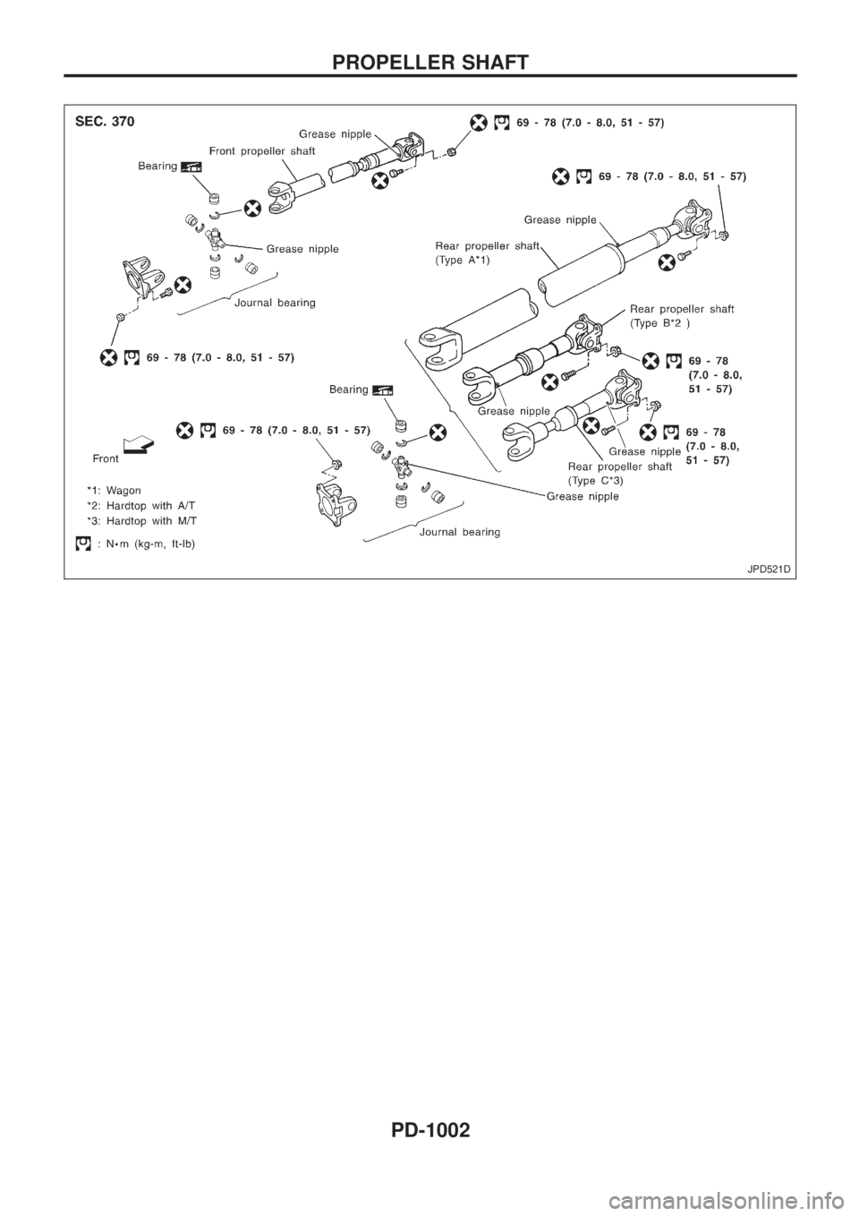
JPD521D
PROPELLER SHAFT
PD-1002