NISSAN PATROL 2006 Service Manual
Manufacturer: NISSAN, Model Year: 2006, Model line: PATROL, Model: NISSAN PATROL 2006Pages: 1226, PDF Size: 37.18 MB
Page 1191 of 1226
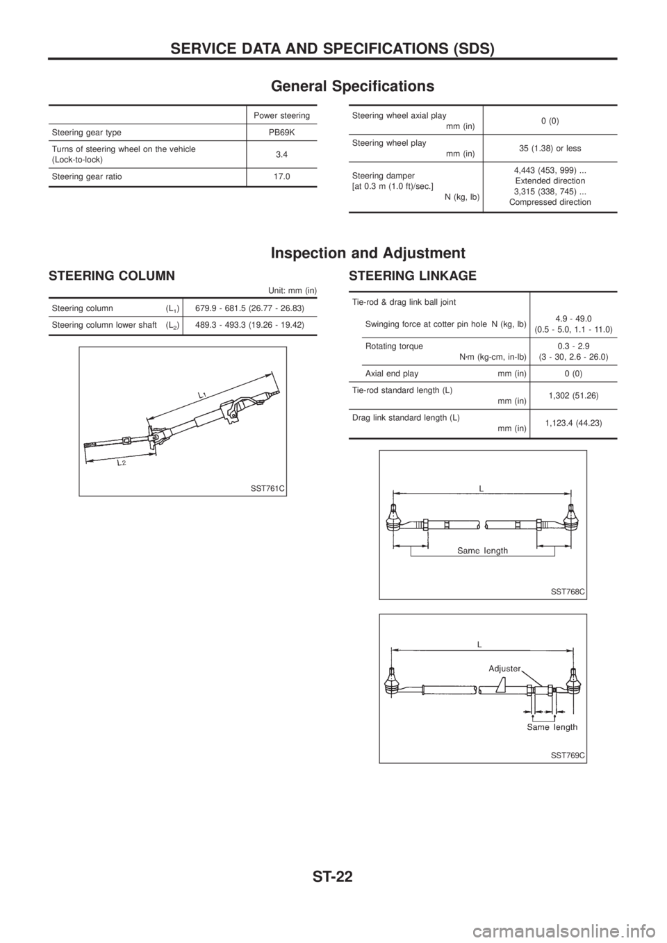
General Speci®cations
Power steering
Steering gear type PB69K
Turns of steering wheel on the vehicle
(Lock-to-lock)3.4
Steering gear ratio 17.0Steering wheel axial play
mm (in)0 (0)
Steering wheel play
mm (in)35 (1.38) or less
Steering damper
[at 0.3 m (1.0 ft)/sec.]
N (kg, lb)4,443 (453, 999) ...
Extended direction
3,315 (338, 745) ...
Compressed direction
Inspection and Adjustment
STEERING COLUMN
Unit: mm (in)
Steering column (L1) 679.9 - 681.5 (26.77 - 26.83)
Steering column lower shaft (L
2) 489.3 - 493.3 (19.26 - 19.42)
STEERING LINKAGE
Tie-rod & drag link ball joint
Swinging force at cotter pin hole N (kg, lb)4.9 - 49.0
(0.5 - 5.0, 1.1 - 11.0)
Rotating torque
Nzm (kg-cm, in-lb)0.3 - 2.9
(3 - 30, 2.6 - 26.0)
Axial end play mm (in) 0 (0)
Tie-rod standard length (L)
mm (in)1,302 (51.26)
Drag link standard length (L)
mm (in)1,123.4 (44.23)
SST761C
SST768C
SST769C
SERVICE DATA AND SPECIFICATIONS (SDS)
ST-22
Page 1192 of 1226
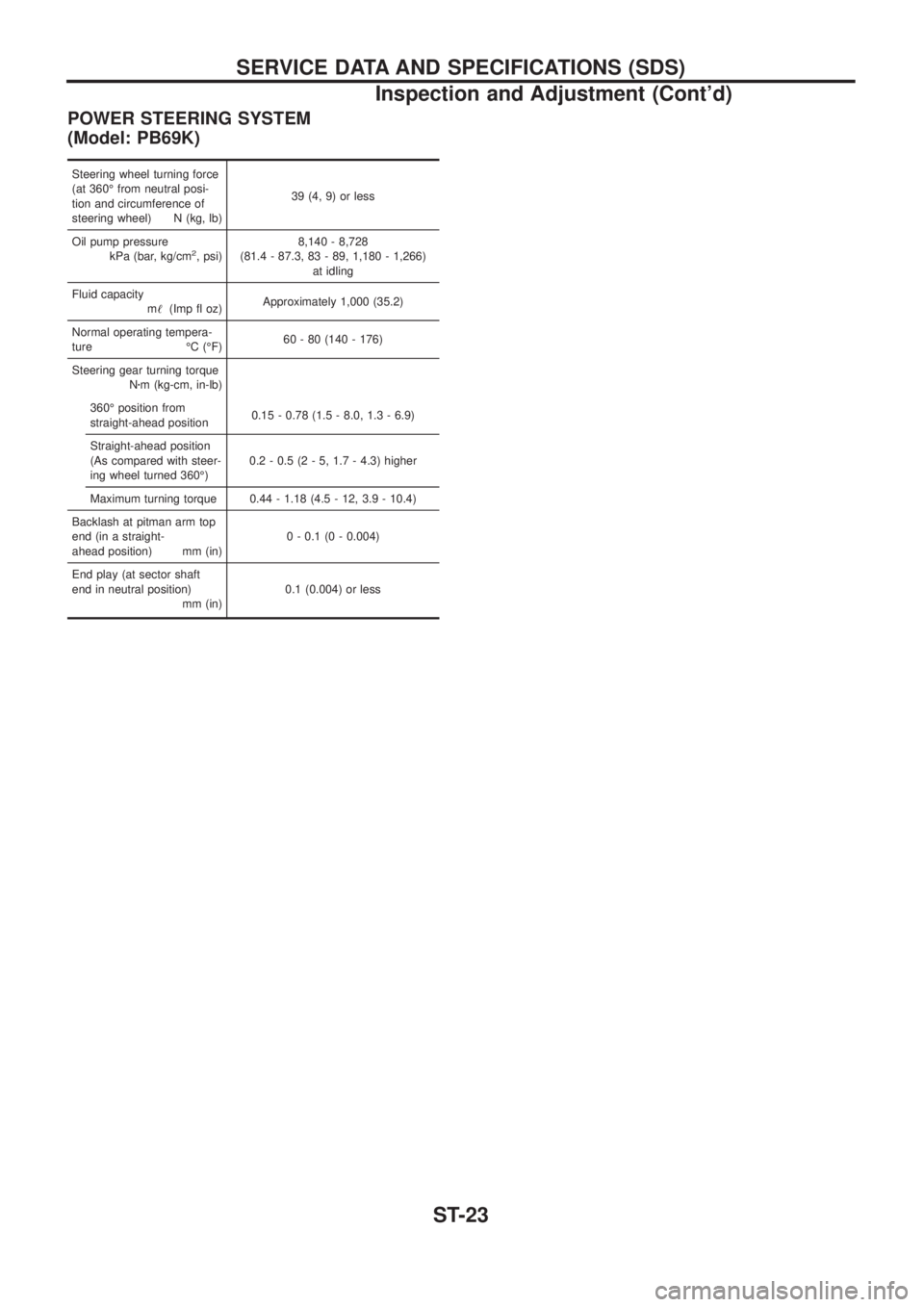
POWER STEERING SYSTEM
(Model: PB69K)
Steering wheel turning force
(at 360É from neutral posi-
tion and circumference of
steering wheel) N (kg, lb)39 (4, 9) or less
Oil pump pressure
kPa (bar, kg/cm
2, psi)8,140 - 8,728
(81.4 - 87.3, 83 - 89, 1,180 - 1,266)
at idling
Fluid capacity
m!(Imp ¯ oz)Approximately 1,000 (35.2)
Normal operating tempera-
ture ÉC (ÉF)60 - 80 (140 - 176)
Steering gear turning torque
Nzm (kg-cm, in-lb)
360É position from
straight-ahead position0.15 - 0.78 (1.5 - 8.0, 1.3 - 6.9)
Straight-ahead position
(As compared with steer-
ing wheel turned 360É)0.2 - 0.5 (2 - 5, 1.7 - 4.3) higher
Maximum turning torque 0.44 - 1.18 (4.5 - 12, 3.9 - 10.4)
Backlash at pitman arm top
end (in a straight-
ahead position) mm (in)0 - 0.1 (0 - 0.004)
End play (at sector shaft
end in neutral position)
mm (in)0.1 (0.004) or less
SERVICE DATA AND SPECIFICATIONS (SDS)
Inspection and Adjustment (Cont'd)
ST-23
Page 1193 of 1226
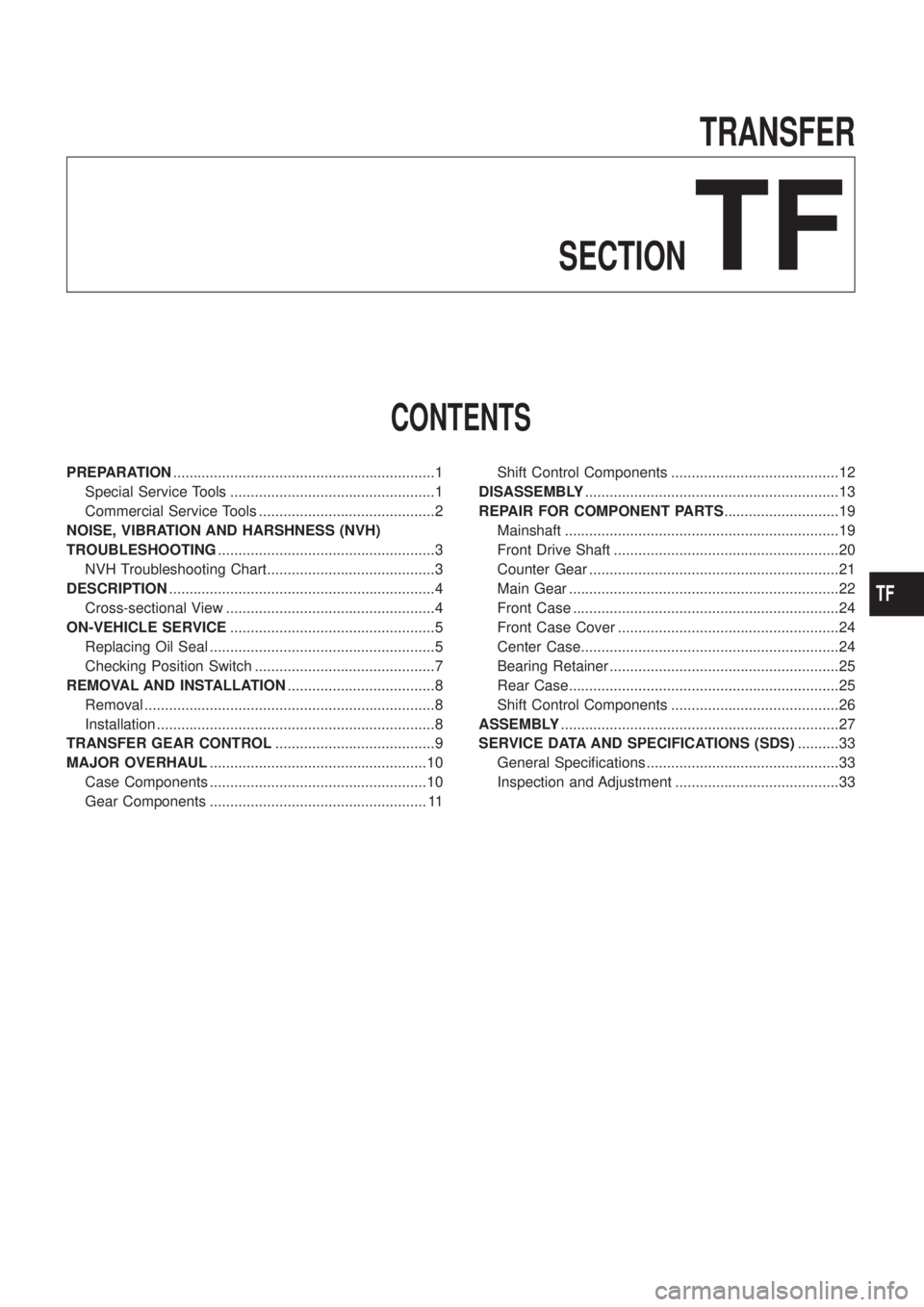
TRANSFER
SECTION
TF
CONTENTS
PREPARATION................................................................1
Special Service Tools ..................................................1
Commercial Service Tools ...........................................2
NOISE, VIBRATION AND HARSHNESS (NVH)
TROUBLESHOOTING.....................................................3
NVH Troubleshooting Chart.........................................3
DESCRIPTION.................................................................4
Cross-sectional View ...................................................4
ON-VEHICLE SERVICE..................................................5
Replacing Oil Seal .......................................................5
Checking Position Switch ............................................7
REMOVAL AND INSTALLATION....................................8
Removal .......................................................................8
Installation ....................................................................8
TRANSFER GEAR CONTROL.......................................9
MAJOR OVERHAUL.....................................................10
Case Components .....................................................10
Gear Components ..................................................... 11Shift Control Components .........................................12
DISASSEMBLY..............................................................13
REPAIR FOR COMPONENT PARTS............................19
Mainshaft ...................................................................19
Front Drive Shaft .......................................................20
Counter Gear .............................................................21
Main Gear ..................................................................22
Front Case .................................................................24
Front Case Cover ......................................................24
Center Case...............................................................24
Bearing Retainer ........................................................25
Rear Case..................................................................25
Shift Control Components .........................................26
ASSEMBLY....................................................................27
SERVICE DATA AND SPECIFICATIONS (SDS)..........33
General Speci®cations ...............................................33
Inspection and Adjustment ........................................33
TF
Page 1194 of 1226
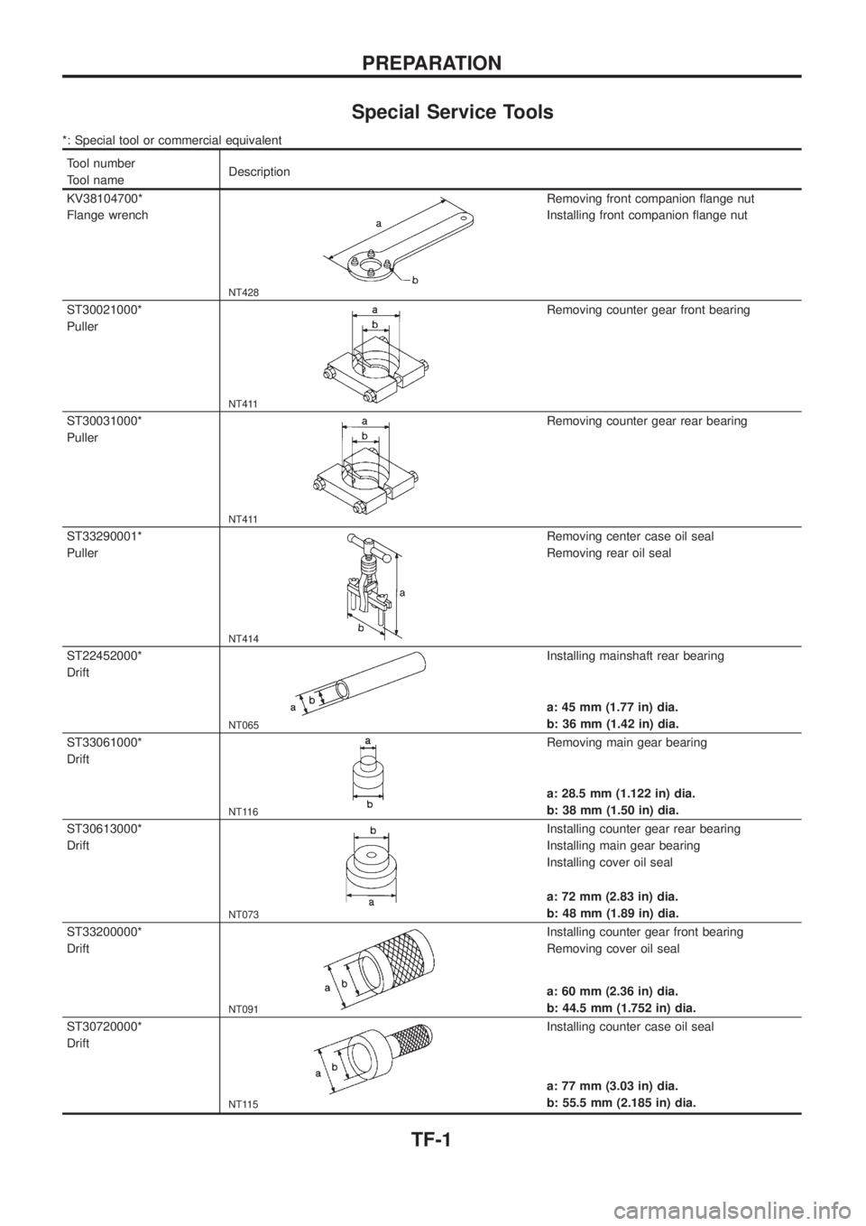
Special Service Tools
*: Special tool or commercial equivalent
Tool number
Tool nameDescription
KV38104700*
Flange wrench
NT428
Removing front companion ¯ange nut
Installing front companion ¯ange nut
ST30021000*
Puller
NT411
Removing counter gear front bearing
ST30031000*
Puller
NT411
Removing counter gear rear bearing
ST33290001*
Puller
NT414
Removing center case oil seal
Removing rear oil seal
ST22452000*
Drift
NT065
Installing mainshaft rear bearing
a: 45 mm (1.77 in) dia.
b: 36 mm (1.42 in) dia.
ST33061000*
Drift
NT116
Removing main gear bearing
a: 28.5 mm (1.122 in) dia.
b: 38 mm (1.50 in) dia.
ST30613000*
Drift
NT073
Installing counter gear rear bearing
Installing main gear bearing
Installing cover oil seal
a: 72 mm (2.83 in) dia.
b: 48 mm (1.89 in) dia.
ST33200000*
Drift
NT091
Installing counter gear front bearing
Removing cover oil seal
a: 60 mm (2.36 in) dia.
b: 44.5 mm (1.752 in) dia.
ST30720000*
Drift
NT115
Installing counter case oil seal
a: 77 mm (3.03 in) dia.
b: 55.5 mm (2.185 in) dia.
PREPARATION
TF-1
Page 1195 of 1226
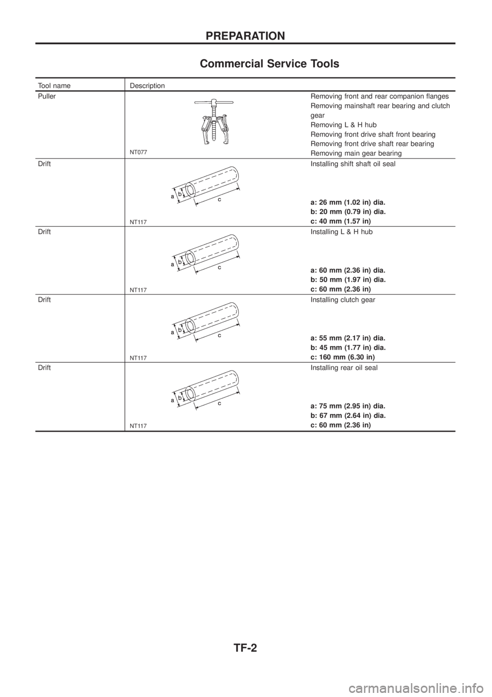
Commercial Service Tools
Tool name Description
Puller
NT077
Removing front and rear companion ¯anges
Removing mainshaft rear bearing and clutch
gear
Removing L & H hub
Removing front drive shaft front bearing
Removing front drive shaft rear bearing
Removing main gear bearing
Drift
NT117
Installing shift shaft oil seal
a: 26 mm (1.02 in) dia.
b: 20 mm (0.79 in) dia.
c: 40 mm (1.57 in)
Drift
NT117
Installing L & H hub
a: 60 mm (2.36 in) dia.
b: 50 mm (1.97 in) dia.
c: 60 mm (2.36 in)
Drift
NT117
Installing clutch gear
a: 55 mm (2.17 in) dia.
b: 45 mm (1.77 in) dia.
c: 160 mm (6.30 in)
Drift
NT117
Installing rear oil seal
a: 75 mm (2.95 in) dia.
b: 67 mm (2.64 in) dia.
c: 60 mm (2.36 in)
PREPARATION
TF-2
Page 1196 of 1226
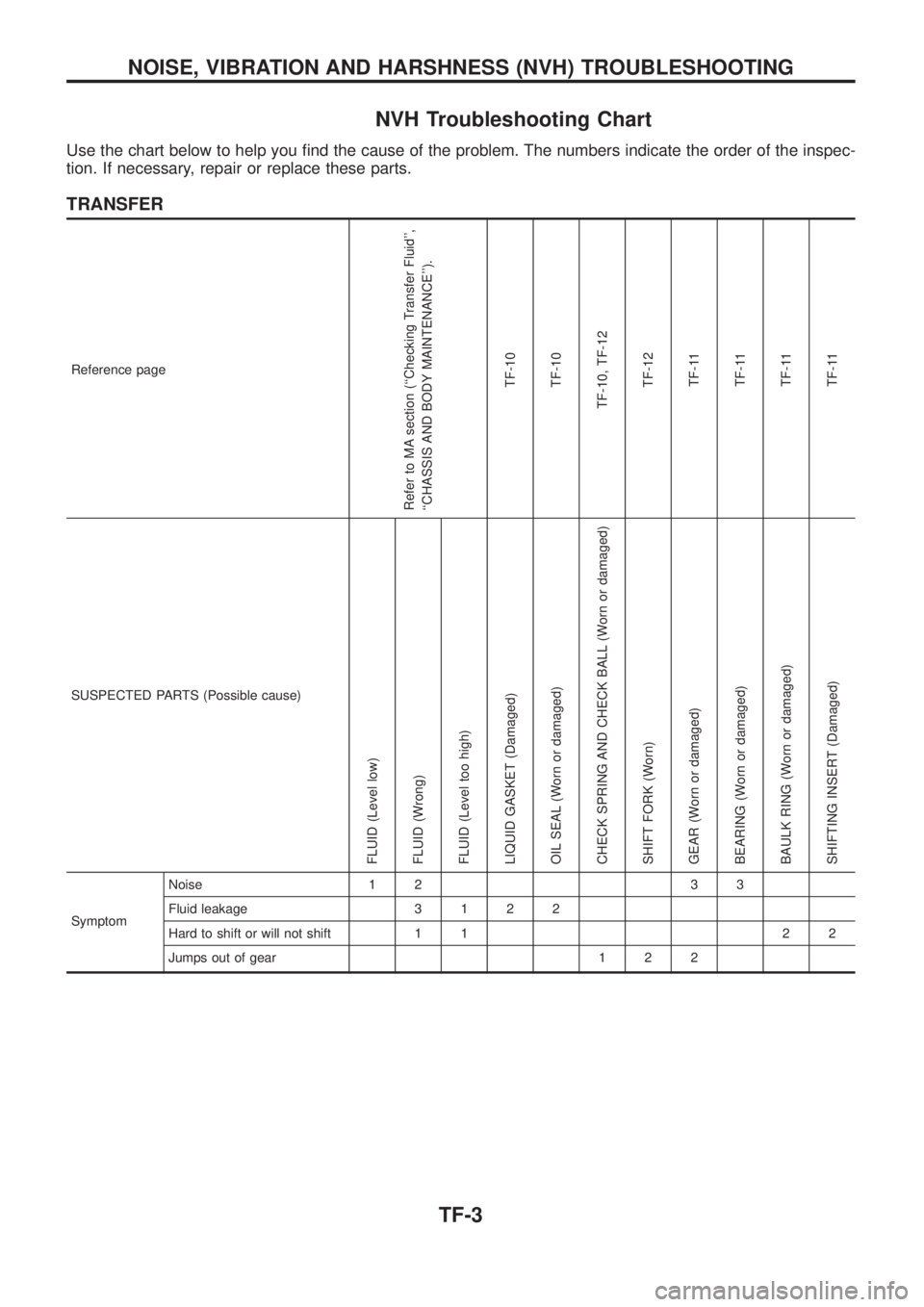
NVH Troubleshooting Chart
Use the chart below to help you ®nd the cause of the problem. The numbers indicate the order of the inspec-
tion. If necessary, repair or replace these parts.
TRANSFER
Reference page
Refer to MA section (``Checking Transfer Fluid'',
``CHASSIS AND BODY MAINTENANCE'').
TF-10
TF-10
TF-10, TF-12
TF-12
TF-11
TF-11
TF-11
TF-11
SUSPECTED PARTS (Possible cause)
FLUID (Level low)
FLUID (Wrong)
FLUID (Level too high)
LIQUID GASKET (Damaged)
OIL SEAL (Worn or damaged)
CHECK SPRING AND CHECK BALL (Worn or damaged)
SHIFT FORK (Worn)
GEAR (Worn or damaged)
BEARING (Worn or damaged)
BAULK RING (Worn or damaged)
SHIFTING INSERT (Damaged)
SymptomNoise 1 2 3 3
Fluid leakage3122
Hard to shift or will not shift 1 1 2 2
Jumps out of gear 1 2 2
NOISE, VIBRATION AND HARSHNESS (NVH) TROUBLESHOOTING
TF-3
Page 1197 of 1226
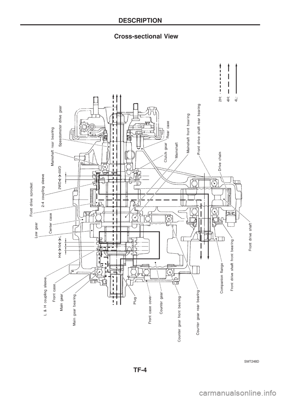
Cross-sectional View
SMT248D
DESCRIPTION
TF-4
Page 1198 of 1226
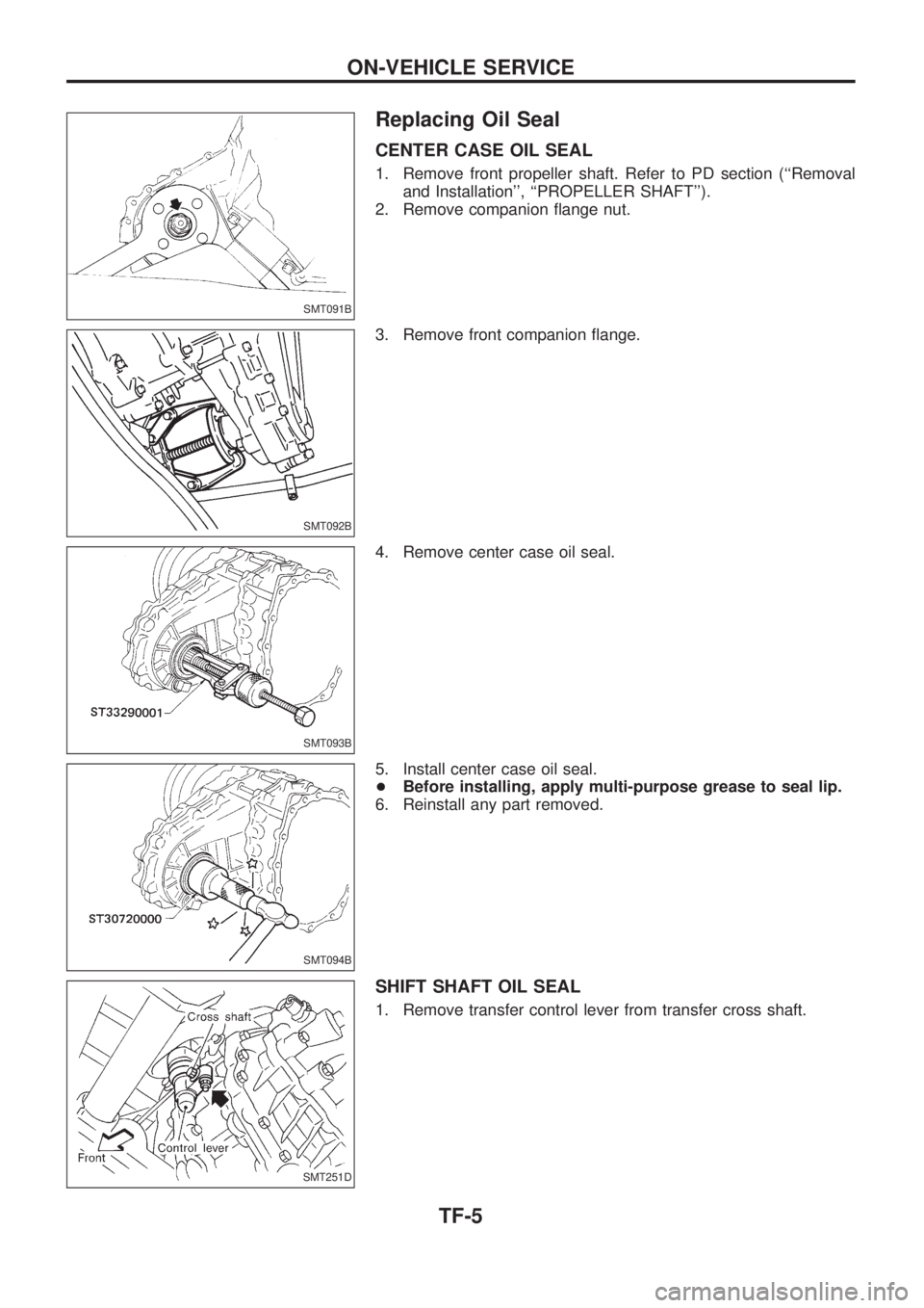
Replacing Oil Seal
CENTER CASE OIL SEAL
1. Remove front propeller shaft. Refer to PD section (``Removal
and Installation'', ``PROPELLER SHAFT'').
2. Remove companion ¯ange nut.
3. Remove front companion ¯ange.
4. Remove center case oil seal.
5. Install center case oil seal.
+Before installing, apply multi-purpose grease to seal lip.
6. Reinstall any part removed.
SHIFT SHAFT OIL SEAL
1. Remove transfer control lever from transfer cross shaft.
SMT091B
SMT092B
SMT093B
SMT094B
SMT251D
ON-VEHICLE SERVICE
TF-5
Page 1199 of 1226
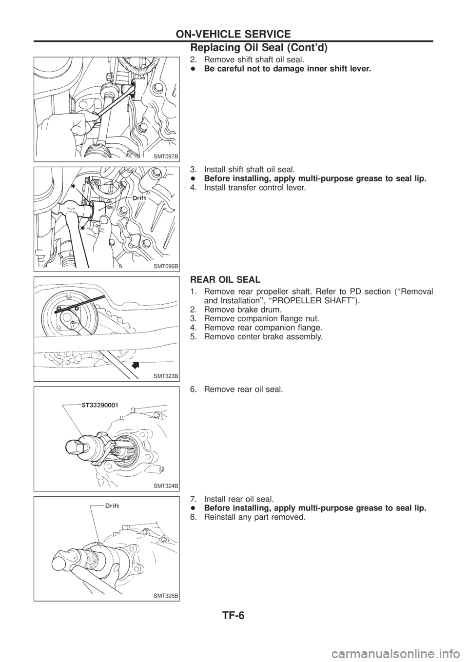
2. Remove shift shaft oil seal.
+Be careful not to damage inner shift lever.
3. Install shift shaft oil seal.
+Before installing, apply multi-purpose grease to seal lip.
4. Install transfer control lever.
REAR OIL SEAL
1. Remove rear propeller shaft. Refer to PD section (``Removal
and Installation'', ``PROPELLER SHAFT'').
2. Remove brake drum.
3. Remove companion ¯ange nut.
4. Remove rear companion ¯ange.
5. Remove center brake assembly.
6. Remove rear oil seal.
7. Install rear oil seal.
+Before installing, apply multi-purpose grease to seal lip.
8. Reinstall any part removed.
SMT097B
SMT096B
SMT323B
SMT324B
SMT325B
ON-VEHICLE SERVICE
Replacing Oil Seal (Cont'd)
TF-6
Page 1200 of 1226
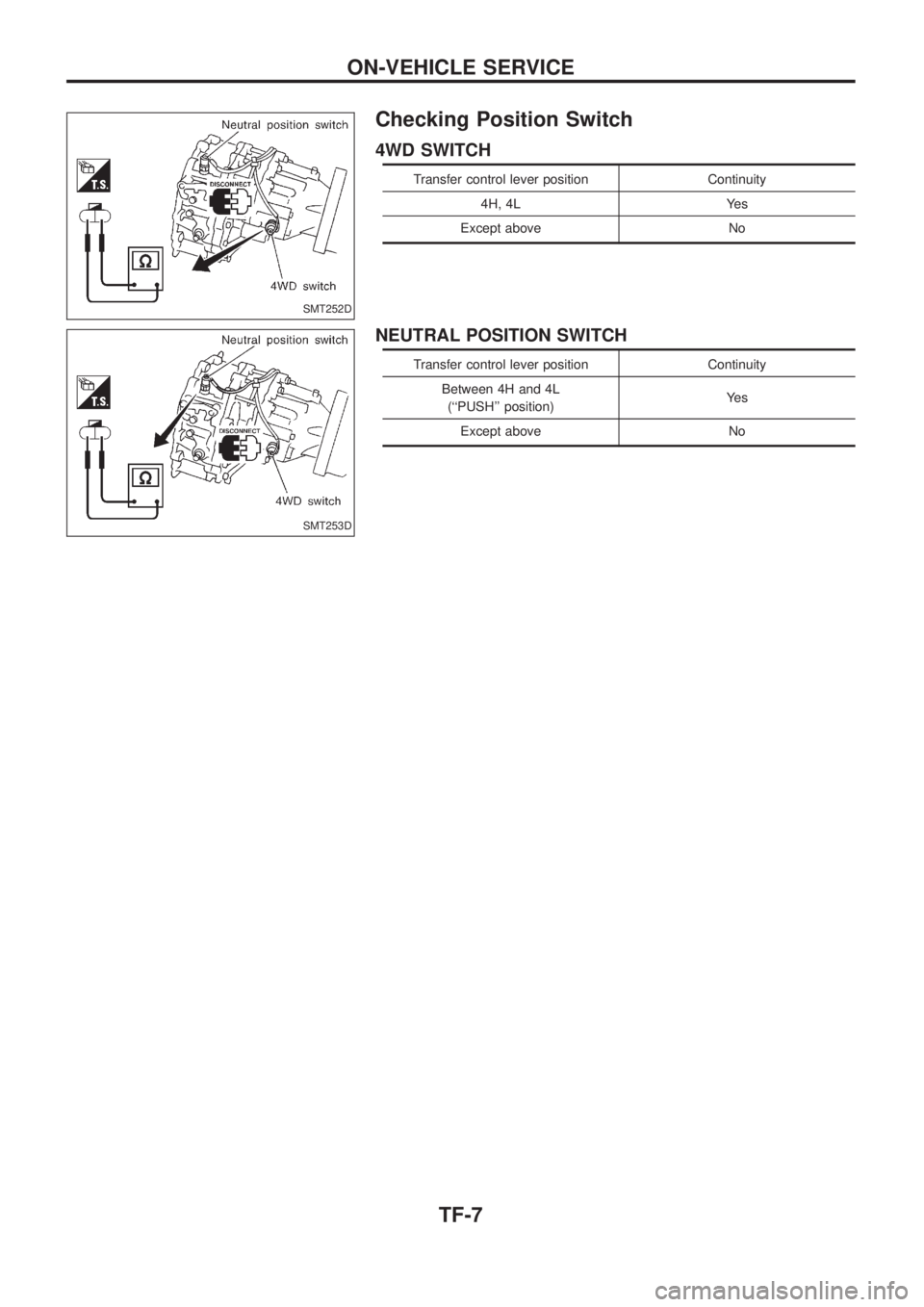
Checking Position Switch
4WD SWITCH
Transfer control lever position Continuity
4H, 4L Yes
Except above No
NEUTRAL POSITION SWITCH
Transfer control lever position Continuity
Between 4H and 4L
(``PUSH'' position)Ye s
Except above No
SMT252D
SMT253D
ON-VEHICLE SERVICE
TF-7