NISSAN PICK-UP 1998 Repair Manual
PICK-UP 1998
NISSAN
NISSAN
https://www.carmanualsonline.info/img/5/57374/w960_57374-0.png
NISSAN PICK-UP 1998 Repair Manual
Trending: belt, trailer, clock setting, engine overheat, four wheel drive, interior lights, tire pressure
Page 901 of 1659
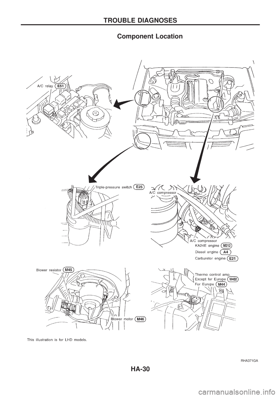
Component Location
RHA371GA
TROUBLE DIAGNOSES
HA-30
Page 902 of 1659
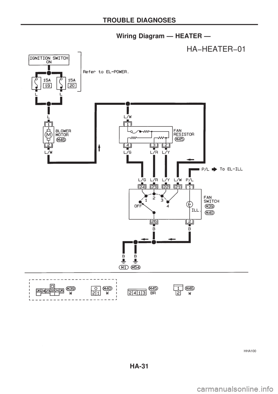
Wiring Diagram Ð HEATER Ð
HHA100
.
HAþHEATERþ01
TROUBLE DIAGNOSES
HA-31
Page 903 of 1659
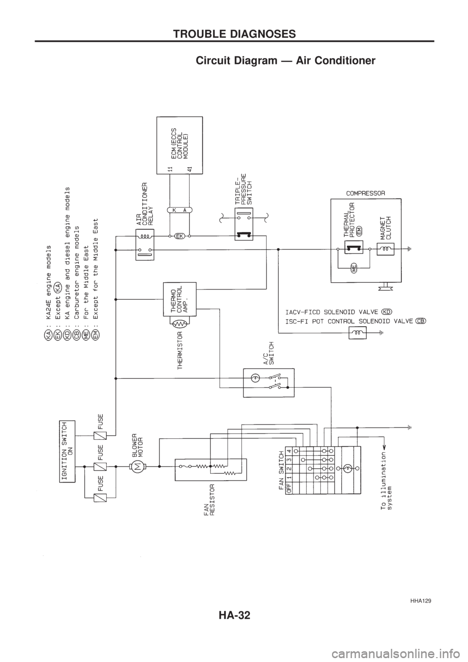
Circuit Diagram Ð Air Conditioner
HHA129
TROUBLE DIAGNOSES
HA-32
Page 904 of 1659
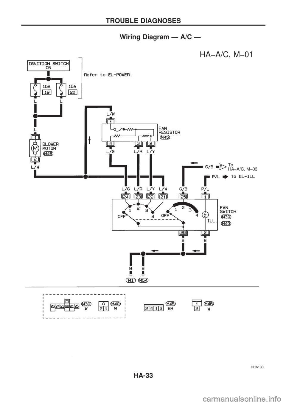
Wiring Diagram Ð A/C Ð
HHA133
.
HAþA/C, Mþ01
.To
HAþA/C, Mþ03
TROUBLE DIAGNOSES
HA-33
Page 905 of 1659
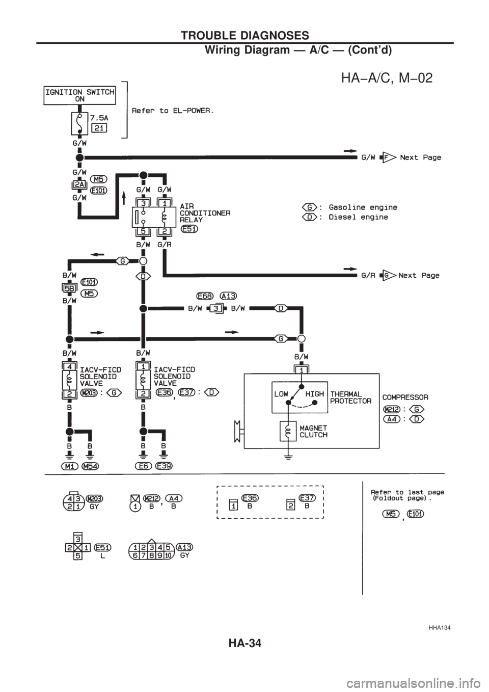
HHA134
.
HAþA/C, Mþ02
TROUBLE DIAGNOSES
Wiring Diagram Ð A/C Ð (Cont'd)
HA-34
Page 906 of 1659
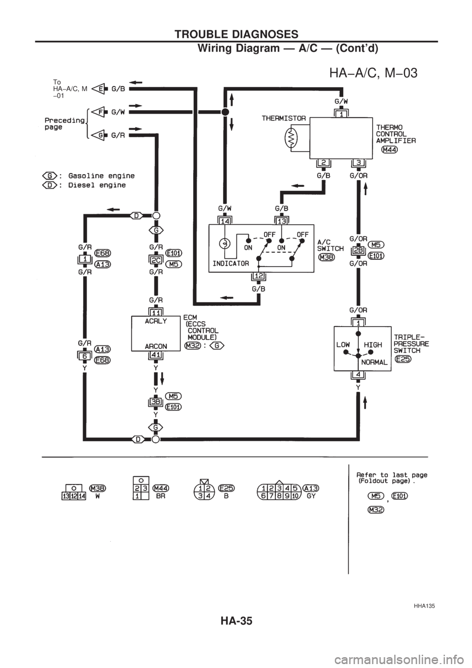
HHA135
.
HAþA/C, Mþ03.To
HAþA/C, M
þ01
TROUBLE DIAGNOSES
Wiring Diagram Ð A/C Ð (Cont'd)
HA-35
Page 907 of 1659
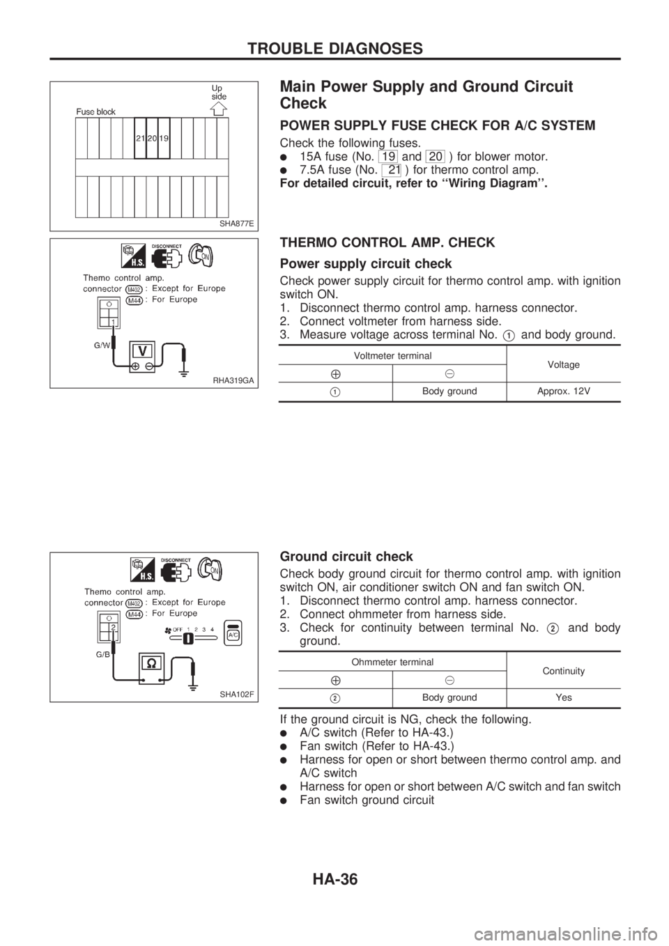
Main Power Supply and Ground Circuit
Check
POWER SUPPLY FUSE CHECK FOR A/C SYSTEM
Check the following fuses.
l15A fuse (No.19 and20 ) for blower motor.
l7.5A fuse (No.21 ) for thermo control amp.
For detailed circuit, refer to ``Wiring Diagram''.
THERMO CONTROL AMP. CHECK
Power supply circuit check
Check power supply circuit for thermo control amp. with ignition
switch ON.
1. Disconnect thermo control amp. harness connector.
2. Connect voltmeter from harness side.
3. Measure voltage across terminal No.
V1and body ground.
Voltmeter terminal
Voltage
Å@
V1Body ground Approx. 12V
Ground circuit check
Check body ground circuit for thermo control amp. with ignition
switch ON, air conditioner switch ON and fan switch ON.
1. Disconnect thermo control amp. harness connector.
2. Connect ohmmeter from harness side.
3. Check for continuity between terminal No.
V2and body
ground.
Ohmmeter terminal
Continuity
Å@
V2Body ground Yes
If the ground circuit is NG, check the following.
lA/C switch (Refer to HA-43.)
lFan switch (Refer to HA-43.)
lHarness for open or short between thermo control amp. and
A/C switch
lHarness for open or short between A/C switch and fan switch
lFan switch ground circuit
SHA877E
RHA319GA
SHA102F
TROUBLE DIAGNOSES
HA-36
Page 908 of 1659
INCIDENTFlow chart
No.
1 Fan fails to rotate.
2 Fan does not rotate at 1-speed.
3 Fan does not rotate at 2-speed.
4 Fan does not rotate at 3-speed.
5 Fan does not rotate at 4-speed.
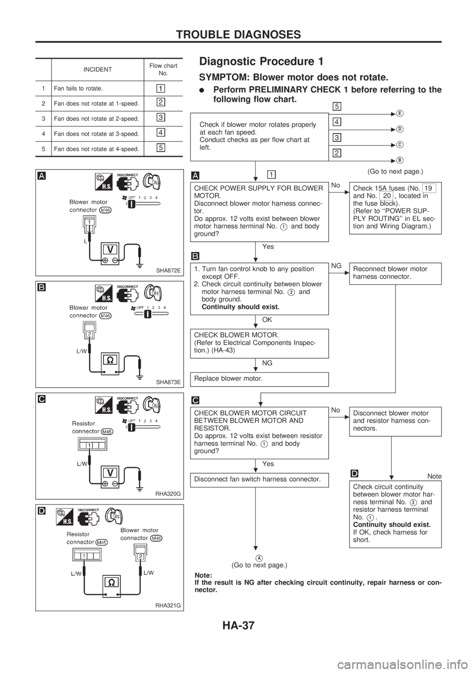
Diagnostic Procedure 1
SYMPTOM: Blower motor does not rotate.
lPerform PRELIMINARY CHECK 1 before referring to the
following flow chart.
Check if blower motor rotates properly
at each fan speed.
Conduct checks as per flow chart at
left.
cVE
cVD
cVC
cVB
(Go to next page.)
CHECK POWER SUPPLY FOR BLOWER
MOTOR.
Disconnect blower motor harness connec-
tor.
Do approx. 12 volts exist between blower
motor harness terminal No.
V1and body
ground?
Yes
cNo
Check 15A fuses (No.19
and No.20 , located in
the fuse block).
(Refer to ``POWER SUP-
PLY ROUTING'' in EL sec-
tion and Wiring Diagram.)
1. Turn fan control knob to any position
except OFF.
2. Check circuit continuity between blower
motor harness terminal No.
V2and
body ground.
Continuity should exist.
OK
cNG
Reconnect blower motor
harness connector.
CHECK BLOWER MOTOR.
(Refer to Electrical Components Inspec-
tion.) (HA-43)
NG
Replace blower motor.
.
CHECK BLOWER MOTOR CIRCUIT
BETWEEN BLOWER MOTOR AND
RESISTOR.
Do approx. 12 volts exist between resistor
harness terminal No.
V1and body
ground?
Yes
cNo
Disconnect blower motor
and resistor harness con-
nectors.
Disconnect fan switch harness connector.Note
Check circuit continuity
between blower motor har-
ness terminal No.
V2and
resistor harness terminal
No.
V1.
Continuity should exist.
If OK, check harness for
short.
VA(Go to next page.)
Note:
If the result is NG after checking circuit continuity, repair harness or con-
nector.
SHA872E
SHA873E
RHA320G
RHA321G
.
.
.
.
..
.
TROUBLE DIAGNOSES
HA-37
Page 909 of 1659
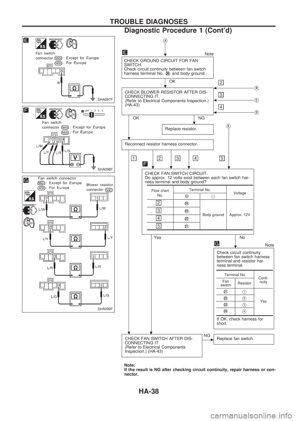
VA
Note
CHECK GROUND CIRCUIT FOR FAN
SWITCH.
Check circuit continuity between fan switch
harness terminal No.
V26and body ground.
OK
CHECK BLOWER RESISTOR AFTER DIS-
CONNECTING IT.
(Refer to Electrical Components Inspection.)
(HA-43)
OK NG
bVB
bVC
bVD
Replace resistor.VE
Reconnect resistor harness connector.
...
CHECK FAN SWITCH CIRCUIT.
Do approx. 12 volts exist between each fan switch har-
ness terminal and body ground?
Yes No
.
Note
Check circuit continuity
between fan switch harness
terminal and resistor har-
ness terminal.
If OK, check harness for
short.
CHECK FAN SWITCH AFTER DIS-
CONNECTING IT.
(Refer to Electrical Components
Inspection.) (HA-43)cNG
Replace fan switch.
Note:
If the result is NG after checking circuit continuity, repair harness or con-
nector.
Flow chart
No.Terminal No.
Voltage
Å@
V24
Body ground Approx. 12VV23
V22
V21
Terminal No.
Conti-
nuity Fan
switchResistor
V21V1
YesV22V2
V23V3
V24V4
SHA097F
SHA098F
SHA099F
.
.
.
.
.
.
.
TROUBLE DIAGNOSES
Diagnostic Procedure 1 (Cont'd)
HA-38
Page 910 of 1659
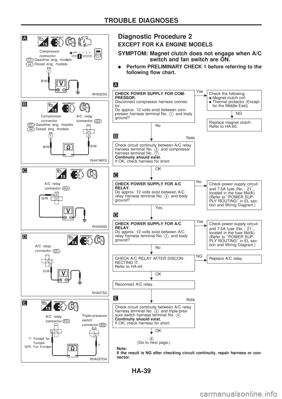
Diagnostic Procedure 2
EXCEPT FOR KA ENGINE MODELS
SYMPTOM: Magnet clutch does not engage when A/C
switch and fan switch are ON.
lPerform PRELIMINARY CHECK 1 before referring to the
following flow chart.
CHECK POWER SUPPLY FOR COM-
PRESSOR.
Disconnect compressor harness connec-
tor.
Do approx. 12 volts exist between com-
pressor harness terminal No.
V1and body
ground?
No
cYes
Check the following.
lMagnet clutch coillThermal protector (Except
for the Middle East)
NG
Replace magnet clutch.
Refer to HA-60.
Note
Check circuit continuity between A/C relay
harness terminal No.
V5and compressor
harness terminal No.
V1.
Continuity should exist.
If OK, check harness for short.
OK
CHECK POWER SUPPLY FOR A/C
RELAY.
Do approx. 12 volts exist between A/C
relay harness terminal No.
V3and body
ground?
Yes
cNo
Check power supply circuit
and 7.5A fuse (No.
21 ,
located in the fuse block).
(Refer to ``POWER SUP-
PLY ROUTING'' in EL sec-
tion and Wiring Diagram.)
CHECK POWER SUPPLY FOR A/C
RELAY.
Do approx. 12 volts exist between A/C
relay harness terminal No.
V1and body
ground?
No
cYes
Check power supply circuit
and 7.5A fuse (No.
21 ,
located in the fuse block).
(Refer to ``POWER SUP-
PLY ROUTING'' in EL sec-
tion and Wiring Diagram.)
CHECK A/C RELAY AFTER DISCON-
NECTING IT.
Refer to HA-44.
OK
cNG
Replace A/C relay.
Reconnect A/C relay.
Note
Check circuit continuity between A/C relay
harness terminal No.
V2and triple-pres-
sure switch harness terminal No.
V4.
Continuity should exist.
If OK, check harness for short.
OK
VA(Go to next page.)
Note:
If the result is NG after checking circuit continuity, repair harness or con-
nector.
RHA325G
RHA748FD
RHA359G
RHA375G
RHA327GA
.
.
.
.
.
.
.
.
TROUBLE DIAGNOSES
HA-39
Trending: check engine light, remote start, stop start, tire type, brake pads replacement, headlights, fog light
