NISSAN PICK-UP 1998 Repair Manual
Manufacturer: NISSAN, Model Year: 1998, Model line: PICK-UP, Model: NISSAN PICK-UP 1998Pages: 1659, PDF Size: 53.39 MB
Page 881 of 1659
Precautions for Service Equipment
RECOVERY/RECYCLING EQUIPMENT
Be certain to follow the manufacturers instructions for machine
operation and machine maintenance. Never introduce any refrig-
erant other than that specified into the machine.
ELECTRONIC LEAK DETECTOR
Be certain to follow the manufacturer's instructions for tester
operation and tester maintenance.
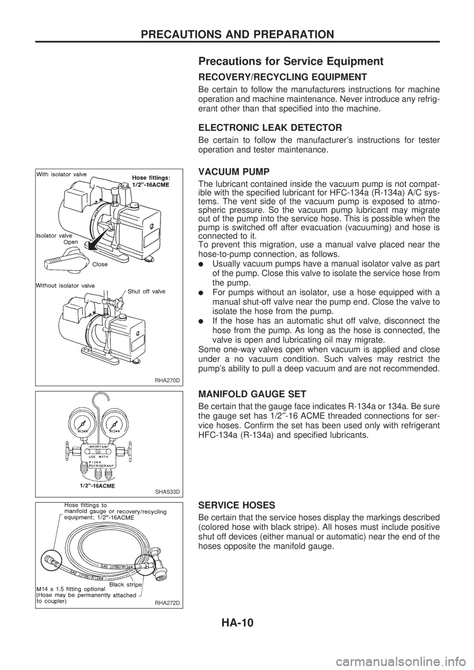
VACUUM PUMP
The lubricant contained inside the vacuum pump is not compat-
ible with the specified lubricant for HFC-134a (R-134a) A/C sys-
tems. The vent side of the vacuum pump is exposed to atmo-
spheric pressure. So the vacuum pump lubricant may migrate
out of the pump into the service hose. This is possible when the
pump is switched off after evacuation (vacuuming) and hose is
connected to it.
To prevent this migration, use a manual valve placed near the
hose-to-pump connection, as follows.
lUsually vacuum pumps have a manual isolator valve as part
of the pump. Close this valve to isolate the service hose from
the pump.
lFor pumps without an isolator, use a hose equipped with a
manual shut-off valve near the pump end. Close the valve to
isolate the hose from the pump.
lIf the hose has an automatic shut off valve, disconnect the
hose from the pump. As long as the hose is connected, the
valve is open and lubricating oil may migrate.
Some one-way valves open when vacuum is applied and close
under a no vacuum condition. Such valves may restrict the
pump's ability to pull a deep vacuum and are not recommended.
MANIFOLD GAUGE SET
Be certain that the gauge face indicates R-134a or 134a. Be sure
the gauge set has 1/2²-16 ACME threaded connections for ser-
vice hoses. Confirm the set has been used only with refrigerant
HFC-134a (R-134a) and specified lubricants.
SERVICE HOSES
Be certain that the service hoses display the markings described
(colored hose with black stripe). All hoses must include positive
shut off devices (either manual or automatic) near the end of the
hoses opposite the manifold gauge.
RHA270D
SHA533D
RHA272D
PRECAUTIONS AND PREPARATION
HA-10
Page 882 of 1659
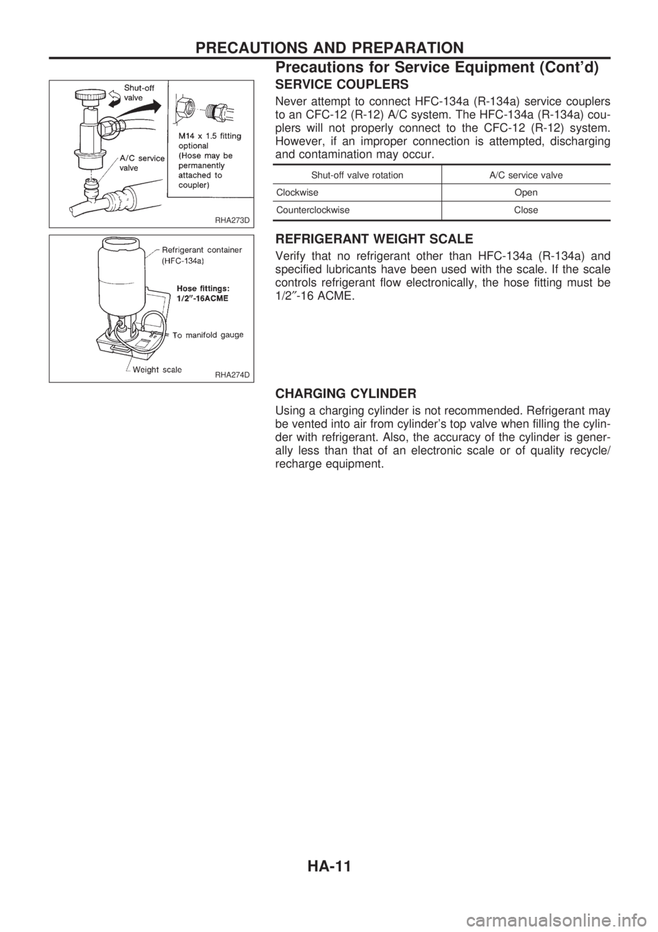
SERVICE COUPLERS
Never attempt to connect HFC-134a (R-134a) service couplers
to an CFC-12 (R-12) A/C system. The HFC-134a (R-134a) cou-
plers will not properly connect to the CFC-12 (R-12) system.
However, if an improper connection is attempted, discharging
and contamination may occur.
Shut-off valve rotation A/C service valve
Clockwise Open
Counterclockwise Close
REFRIGERANT WEIGHT SCALE
Verify that no refrigerant other than HFC-134a (R-134a) and
specified lubricants have been used with the scale. If the scale
controls refrigerant flow electronically, the hose fitting must be
1/2²-16 ACME.
CHARGING CYLINDER
Using a charging cylinder is not recommended. Refrigerant may
be vented into air from cylinder's top valve when filling the cylin-
der with refrigerant. Also, the accuracy of the cylinder is gener-
ally less than that of an electronic scale or of quality recycle/
recharge equipment.
RHA273D
RHA274D
PRECAUTIONS AND PREPARATION
Precautions for Service Equipment (Cont'd)
HA-11
Page 883 of 1659
Refrigeration Cycle
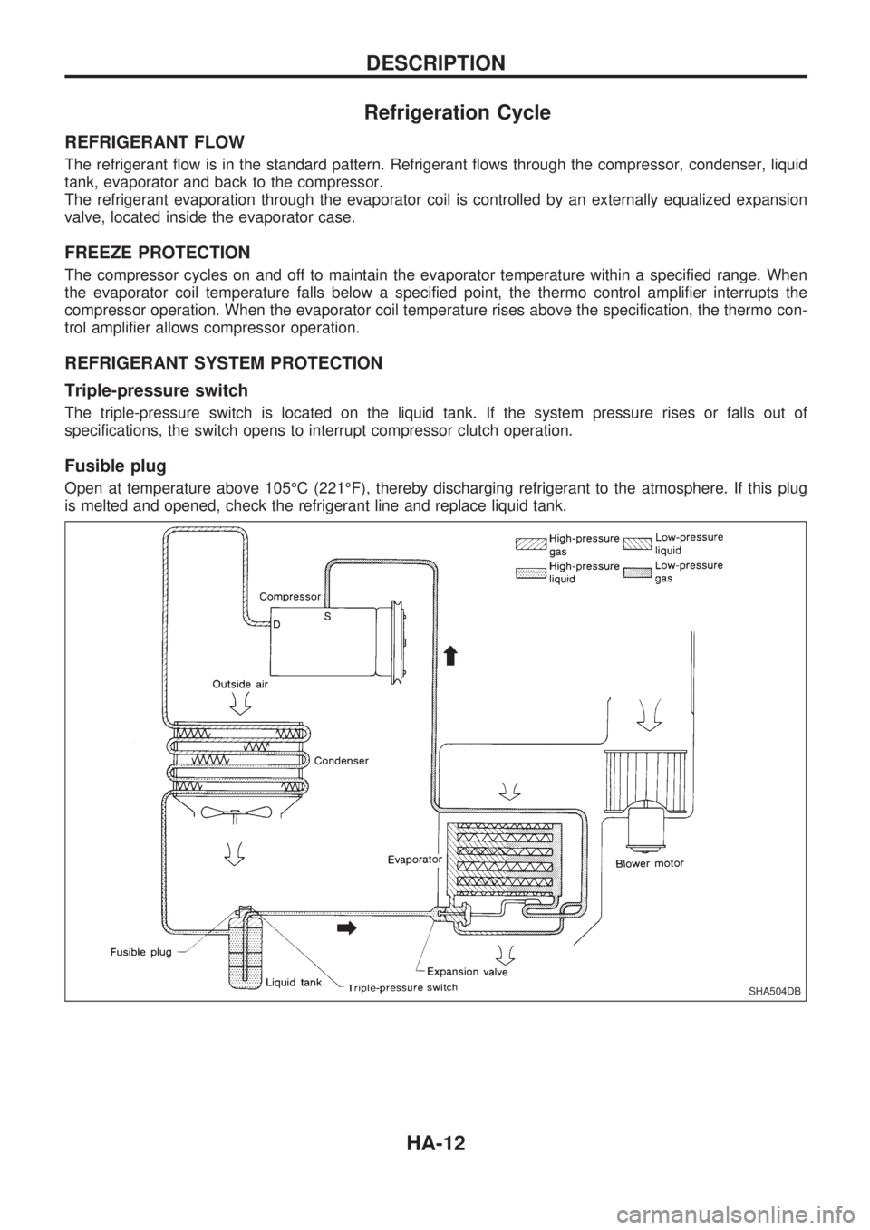
REFRIGERANT FLOW
The refrigerant flow is in the standard pattern. Refrigerant flows through the compressor, condenser, liquid
tank, evaporator and back to the compressor.
The refrigerant evaporation through the evaporator coil is controlled by an externally equalized expansion
valve, located inside the evaporator case.
FREEZE PROTECTION
The compressor cycles on and off to maintain the evaporator temperature within a specified range. When
the evaporator coil temperature falls below a specified point, the thermo control amplifier interrupts the
compressor operation. When the evaporator coil temperature rises above the specification, the thermo con-
trol amplifier allows compressor operation.
REFRIGERANT SYSTEM PROTECTION
Triple-pressure switch
The triple-pressure switch is located on the liquid tank. If the system pressure rises or falls out of
specifications, the switch opens to interrupt compressor clutch operation.
Fusible plug
Open at temperature above 105ÉC (221ÉF), thereby discharging refrigerant to the atmosphere. If this plug
is melted and opened, check the refrigerant line and replace liquid tank.
SHA504DB
DESCRIPTION
HA-12
Page 884 of 1659
Component Layout
RHA343G
DESCRIPTION
HA-13
Page 885 of 1659
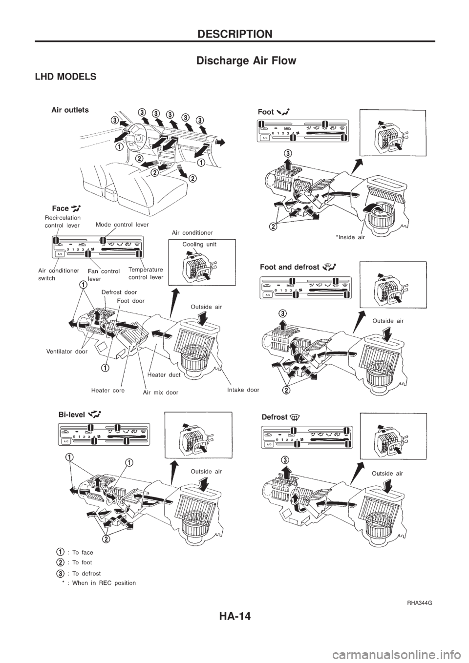
Discharge Air Flow
LHD MODELS
RHA344G
DESCRIPTION
HA-14
Page 886 of 1659
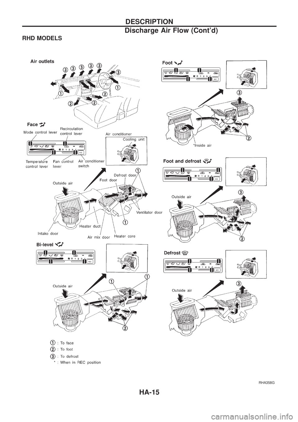
RHD MODELS
RHA358G
DESCRIPTION
Discharge Air Flow (Cont'd)
HA-15
Page 887 of 1659
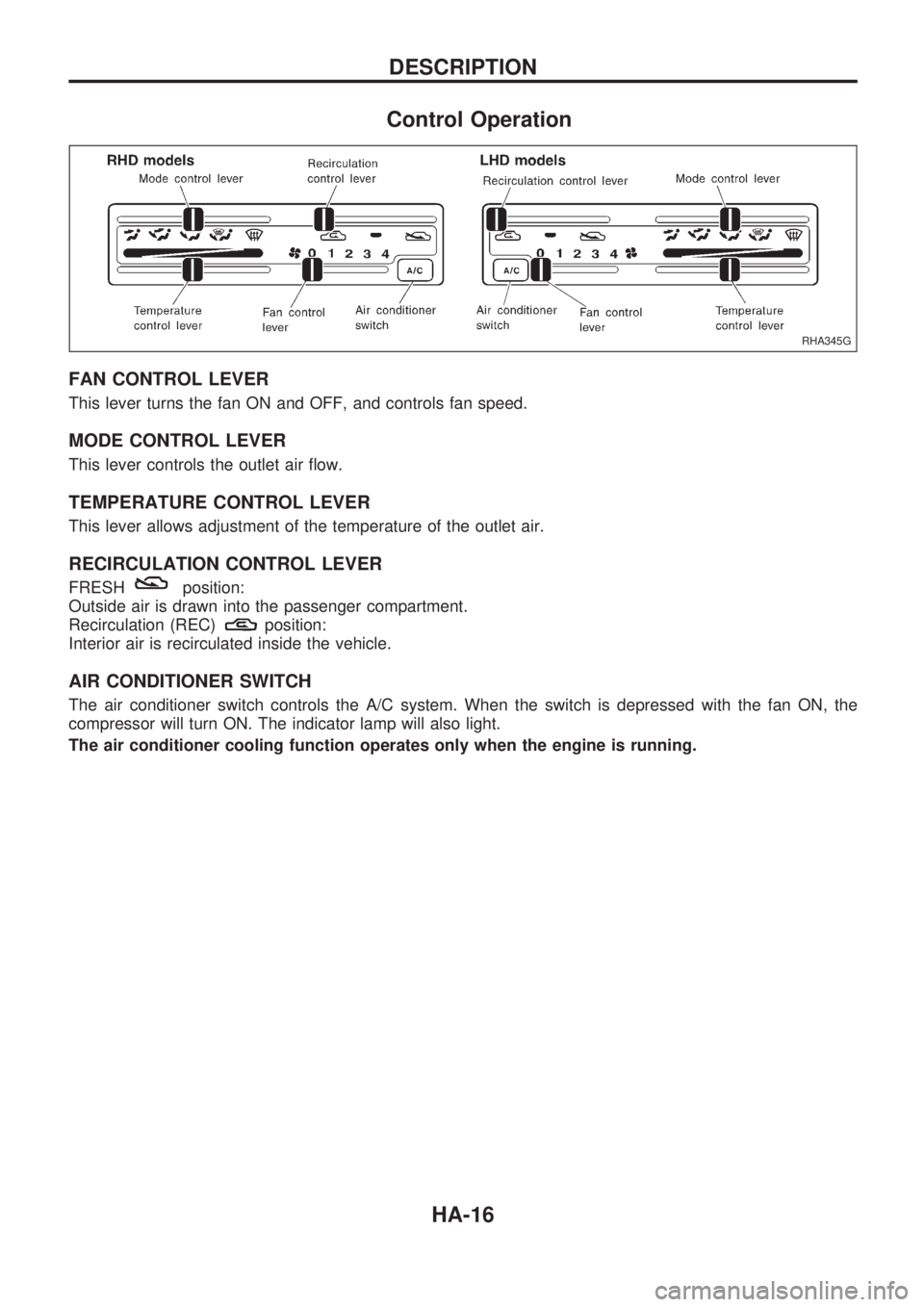
Control Operation
FAN CONTROL LEVER
This lever turns the fan ON and OFF, and controls fan speed.
MODE CONTROL LEVER
This lever controls the outlet air flow.
TEMPERATURE CONTROL LEVER
This lever allows adjustment of the temperature of the outlet air.
RECIRCULATION CONTROL LEVER
FRESHposition:
Outside air is drawn into the passenger compartment.
Recirculation (REC)
position:
Interior air is recirculated inside the vehicle.
AIR CONDITIONER SWITCH
The air conditioner switch controls the A/C system. When the switch is depressed with the fan ON, the
compressor will turn ON. The indicator lamp will also light.
The air conditioner cooling function operates only when the engine is running.
RHA345G
DESCRIPTION
HA-16
Page 888 of 1659
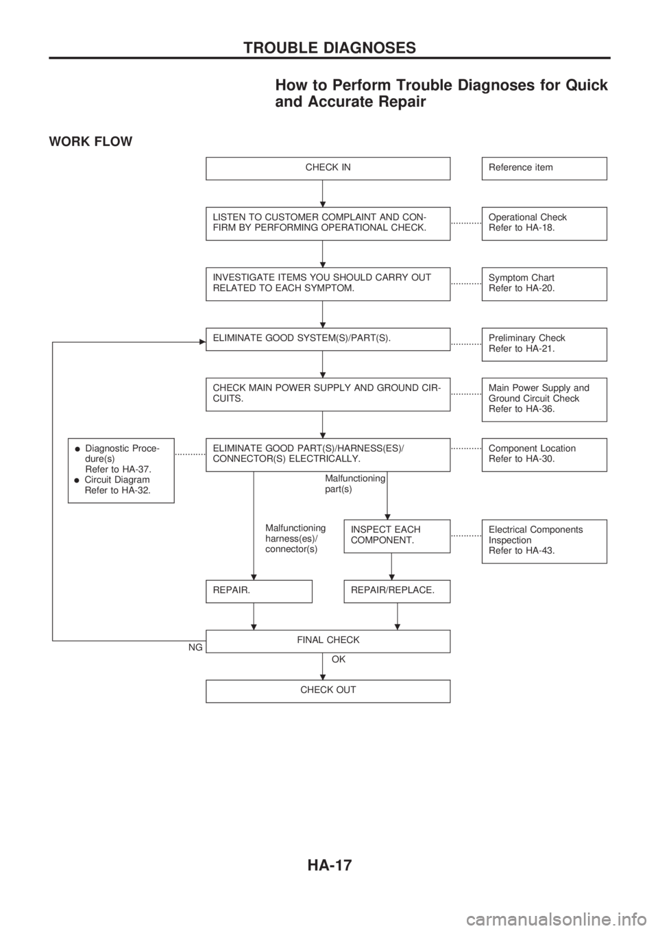
How to Perform Trouble Diagnoses for Quick
and Accurate Repair
WORK FLOW
CHECK INReference item
LISTEN TO CUSTOMER COMPLAINT AND CON-
FIRM BY PERFORMING OPERATIONAL CHECK.............Operational Check
Refer to HA-18.
INVESTIGATE ITEMS YOU SHOULD CARRY OUT
RELATED TO EACH SYMPTOM.............Symptom Chart
Refer to HA-20.
cELIMINATE GOOD SYSTEM(S)/PART(S).............Preliminary Check
Refer to HA-21.
CHECK MAIN POWER SUPPLY AND GROUND CIR-
CUITS.............Main Power Supply and
Ground Circuit Check
Refer to HA-36.
lDiagnostic Proce-
dure(s)
Refer to HA-37.
lCircuit Diagram
Refer to HA-32.
............ELIMINATE GOOD PART(S)/HARNESS(ES)/
CONNECTOR(S) ELECTRICALLY.
Malfunctioning
harness(es)/
connector(s)Malfunctioning
part(s)............
Component Location
Refer to HA-30.INSPECT EACH
COMPONENT.............Electrical Components
Inspection
Refer to HA-43.
REPAIR.REPAIR/REPLACE.
.
NGFINAL CHECK
OK
CHECK OUT
.
.
.
.
.
.
..
.
.
TROUBLE DIAGNOSES
HA-17
Page 889 of 1659
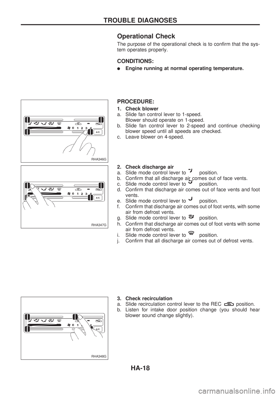
Operational Check
The purpose of the operational check is to confirm that the sys-
tem operates properly.
CONDITIONS:
lEngine running at normal operating temperature.
PROCEDURE:
1. Check blower
a. Slide fan control lever to 1-speed.
Blower should operate on 1-speed.
b. Slide fan control lever to 2-speed and continue checking
blower speed until all speeds are checked.
c. Leave blower on 4-speed.
2. Check discharge air
a. Slide mode control lever to
position.
b. Confirm that all discharge air comes out of face vents.
c. Slide mode control lever to
position.
d. Confirm that discharge air comes out of face vents and foot
vents.
e. Slide mode control lever to
position.
f. Confirm that discharge air comes out of foot vents, with some
air from defrost vents.
g. Slide mode control lever to
position.
h. Confirm that discharge air comes out of foot vents with some
air from defrost vents.
i. Slide mode control lever to
position.
j. Confirm that all discharge air comes out of defrost vents.
3. Check recirculation
a. Slide recirculation control lever to the REC
position.
b. Listen for intake door position change (you should hear
blower sound change slightly).
RHA346G
RHA347G
RHA348G
TROUBLE DIAGNOSES
HA-18
Page 890 of 1659
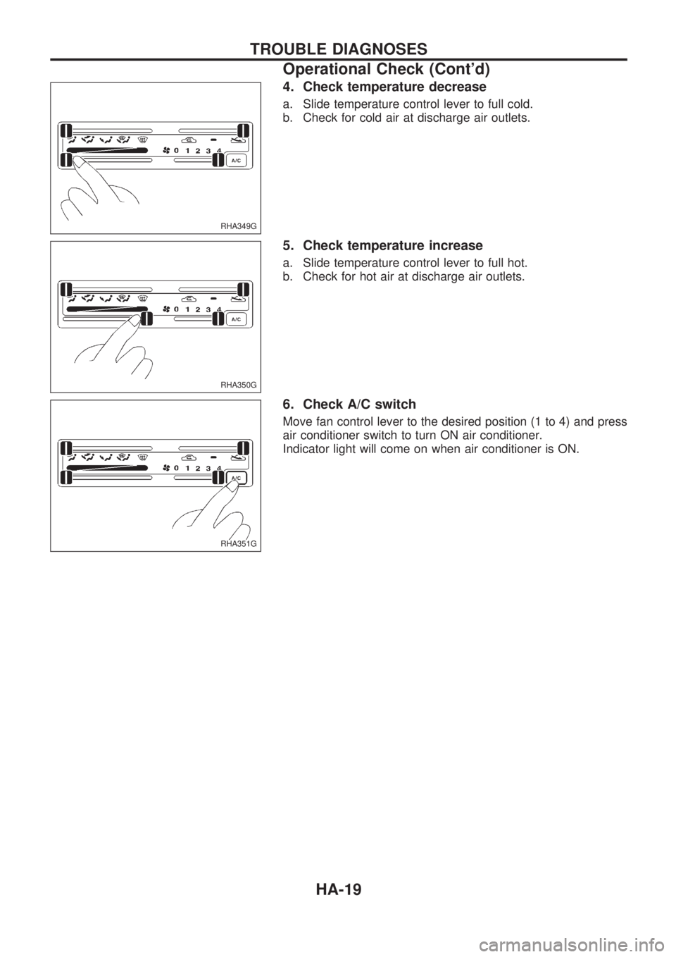
4. Check temperature decrease
a. Slide temperature control lever to full cold.
b. Check for cold air at discharge air outlets.
5. Check temperature increase
a. Slide temperature control lever to full hot.
b. Check for hot air at discharge air outlets.
6. Check A/C switch
Move fan control lever to the desired position (1 to 4) and press
air conditioner switch to turn ON air conditioner.
Indicator light will come on when air conditioner is ON.
RHA349G
RHA350G
RHA351G
TROUBLE DIAGNOSES
Operational Check (Cont'd)
HA-19