NISSAN PICK-UP 1998 Repair Manual
Manufacturer: NISSAN, Model Year: 1998, Model line: PICK-UP, Model: NISSAN PICK-UP 1998Pages: 1659, PDF Size: 53.39 MB
Page 891 of 1659
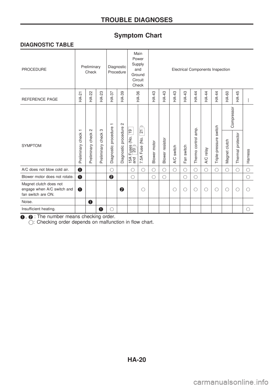
Symptom Chart
DIAGNOSTIC TABLE
PROCEDUREPreliminary
CheckDiagnostic
ProcedureMain
Power
Supply
and
Ground
Circuit
CheckElectrical Components Inspection
REFERENCE PAGE
HA-21
HA-22
HA-23
HA-37
HA-39
HA-36
HA-43
HA-43
HA-43
HA-43
HA-44
HA-44
HA-44
HA-60
HA-45
Ð
SYMPTOM
Preliminary check 1
Preliminary check 2
Preliminary check 3
Diagnostic procedure 1
Diagnostic procedure 2
15A Fuses (No.
19
and
20 )
7.5A Fuse (No.
21 )
Blower motor
Blower resistor
A/C switch
Fan switch
Thermo control amp.
A/C relay
Triple-pressure switch
Compressor
Harness Magnet clutch
Thermal protector
A/C does not blow cold air.j jjjjjjjjjjjj
Blower motor does not rotate.
jjjjj j
Magnet clutch does not
engage when A/C switch and
fan switch are ON.
j jjjjjjjj
Noise.
Insufficient heating.jj
,: The number means checking order.
j: Checking order depends on malfunction in flow chart.
TROUBLE DIAGNOSES
HA-20
Page 892 of 1659
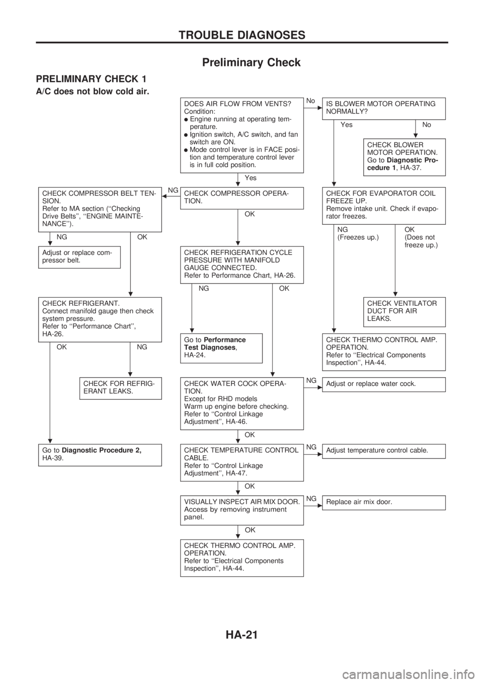
Preliminary Check
PRELIMINARY CHECK 1
A/C does not blow cold air.
DOES AIR FLOW FROM VENTS?
Condition:
lEngine running at operating tem-
perature.
lIgnition switch, A/C switch, and fan
switch are ON.
lMode control lever is in FACE posi-
tion and temperature control lever
is in full cold position.
Yes
cNo
IS BLOWER MOTOR OPERATING
NORMALLY?
Yes No
CHECK BLOWER
MOTOR OPERATION.
Go toDiagnostic Pro-
cedure 1, HA-37.
CHECK COMPRESSOR BELT TEN-
SION.
Refer to MA section (``Checking
Drive Belts'', ``ENGINE MAINTE-
NANCE'').
NG OKNG
bCHECK COMPRESSOR OPERA-
TION.
OKCHECK FOR EVAPORATOR COIL
FREEZE UP.
Remove intake unit. Check if evapo-
rator freezes.
Adjust or replace com-
pressor belt.CHECK REFRIGERATION CYCLE
PRESSURE WITH MANIFOLD
GAUGE CONNECTED.
Refer to Performance Chart, HA-26.
NG OKNG
(Freezes up.)OK
(Does not
freeze up.)
CHECK REFRIGERANT.
Connect manifold gauge then check
system pressure.
Refer to ``Performance Chart'',
HA-26.
OK NGCHECK VENTILATOR
DUCT FOR AIR
LEAKS.Go toPerformance
Test Diagnoses,
HA-24.CHECK THERMO CONTROL AMP.
OPERATION.
Refer to ``Electrical Components
Inspection'', HA-44.
CHECK FOR REFRIG-
ERANT LEAKS.CHECK WATER COCK OPERA-
TION.
Except for RHD models
Warm up engine before checking.
Refer to ``Control Linkage
Adjustment'', HA-46.
OK
cNG
Adjust or replace water cock.
Go toDiagnostic Procedure 2,
HA-39.CHECK TEMPERATURE CONTROL
CABLE.
Refer to ``Control Linkage
Adjustment'', HA-47.
OK
cNG
Adjust temperature control cable.
VISUALLY INSPECT AIR MIX DOOR.Access by removing instrument
panel.
OK
cNG
Replace air mix door.
CHECK THERMO CONTROL AMP.
OPERATION.
Refer to ``Electrical Components
Inspection'', HA-44.
.
..
..
..
..
..
..
.
.
TROUBLE DIAGNOSES
HA-21
Page 893 of 1659
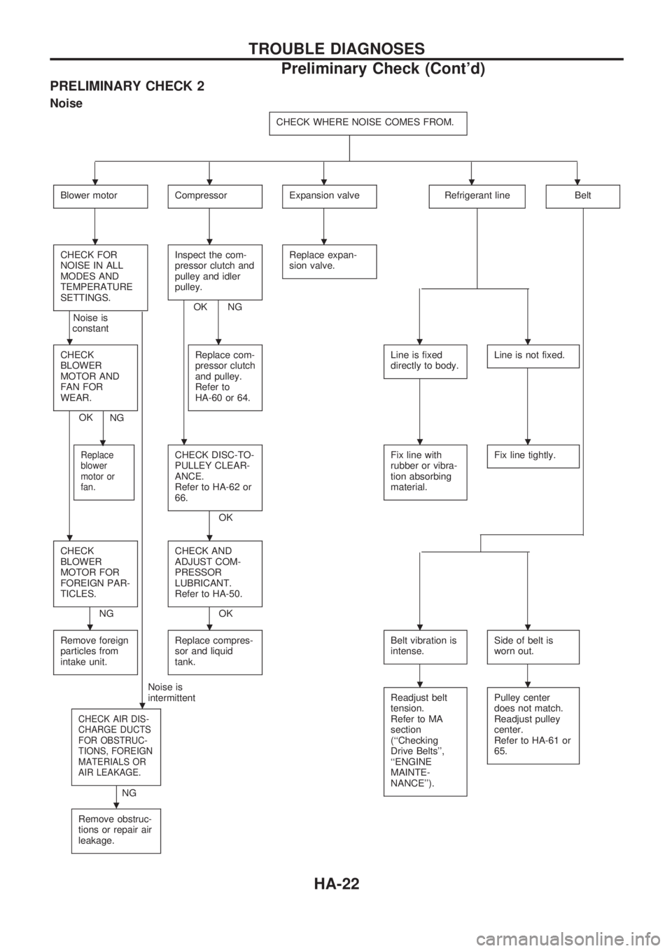
PRELIMINARY CHECK 2
Noise
CHECK WHERE NOISE COMES FROM.
Blower motorCompressorExpansion valveRefrigerant lineBelt
CHECK FOR
NOISE IN ALL
MODES AND
TEMPERATURE
SETTINGS.
Noise is
constant
.
Inspect the com-
pressor clutch and
pulley and idler
pulley.
OK NGReplace expan-
sion valve.
CHECK
BLOWER
MOTOR AND
FAN FOR
WEAR.
OK
.
NGReplace com-
pressor clutch
and pulley.
Refer to
HA-60 or 64.
Line is fixed
directly to body.Line is not fixed.
Replace
blower
motor or
fan.CHECK DISC-TO-
PULLEY CLEAR-
ANCE.
Refer to HA-62 or
66.
OKFix line with
rubber or vibra-
tion absorbing
material.
Fix line tightly.
CHECK
BLOWER
MOTOR FOR
FOREIGN PAR-
TICLES.
NGCHECK AND
ADJUST COM-
PRESSOR
LUBRICANT.
Refer to HA-50.OK
Remove foreign
particles from
intake unit.
Replace compres-
sor and liquid
tank.Belt vibration is
intense.Side of belt is
worn out.
Noise is
intermittent
CHECK AIR DIS-
CHARGE DUCTS
FOR OBSTRUC-
TIONS, FOREIGN
MATERIALS OR
AIR LEAKAGE.
.
NGReadjust belt
tension.
Refer to MA
section
(``Checking
Drive Belts'',
``ENGINE
MAINTE-
NANCE'').
Pulley center
does not match.
Readjust pulley
center.
Refer to HA-61 or
65.
Remove obstruc-
tions or repair air
leakage.
.....
...
....
...
..
....
..
TROUBLE DIAGNOSES
Preliminary Check (Cont'd)
HA-22
Page 894 of 1659
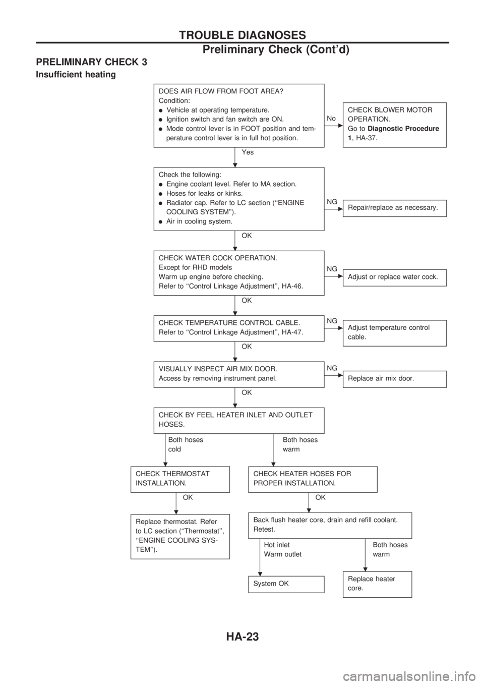
PRELIMINARY CHECK 3
Insufficient heating
DOES AIR FLOW FROM FOOT AREA?
Condition:
lVehicle at operating temperature.
lIgnition switch and fan switch are ON.
lMode control lever is in FOOT position and tem-
perature control lever is in full hot position.
Yes
cNoCHECK BLOWER MOTOR
OPERATION.
Go toDiagnostic Procedure
1, HA-37.
Check the following:
lEngine coolant level. Refer to MA section.
lHoses for leaks or kinks.
lRadiator cap. Refer to LC section (``ENGINE
COOLING SYSTEM'').
lAir in cooling system.
OK
cNG
Repair/replace as necessary.
CHECK WATER COCK OPERATION.
Except for RHD models
Warm up engine before checking.
Refer to ``Control Linkage Adjustment'', HA-46.
OK
cNG
Adjust or replace water cock.
CHECK TEMPERATURE CONTROL CABLE.
Refer to ``Control Linkage Adjustment'', HA-47.
OK
cNG
Adjust temperature control
cable.
VISUALLY INSPECT AIR MIX DOOR.
Access by removing instrument panel.
OK
cNG
Replace air mix door.
CHECK BY FEEL HEATER INLET AND OUTLET
HOSES.
Both hoses
coldBoth hoses
warm
CHECK THERMOSTAT
INSTALLATION.
OKCHECK HEATER HOSES FOR
PROPER INSTALLATION.OK
Replace thermostat. Refer
to LC section (``Thermostat'',
``ENGINE COOLING SYS-
TEM'').
Back flush heater core, drain and refill coolant.
Retest.
Hot inlet
Warm outletBoth hoses
warm
System OK
Replace heater
core.
.
.
.
.
.
..
..
..
TROUBLE DIAGNOSES
Preliminary Check (Cont'd)
HA-23
Page 895 of 1659
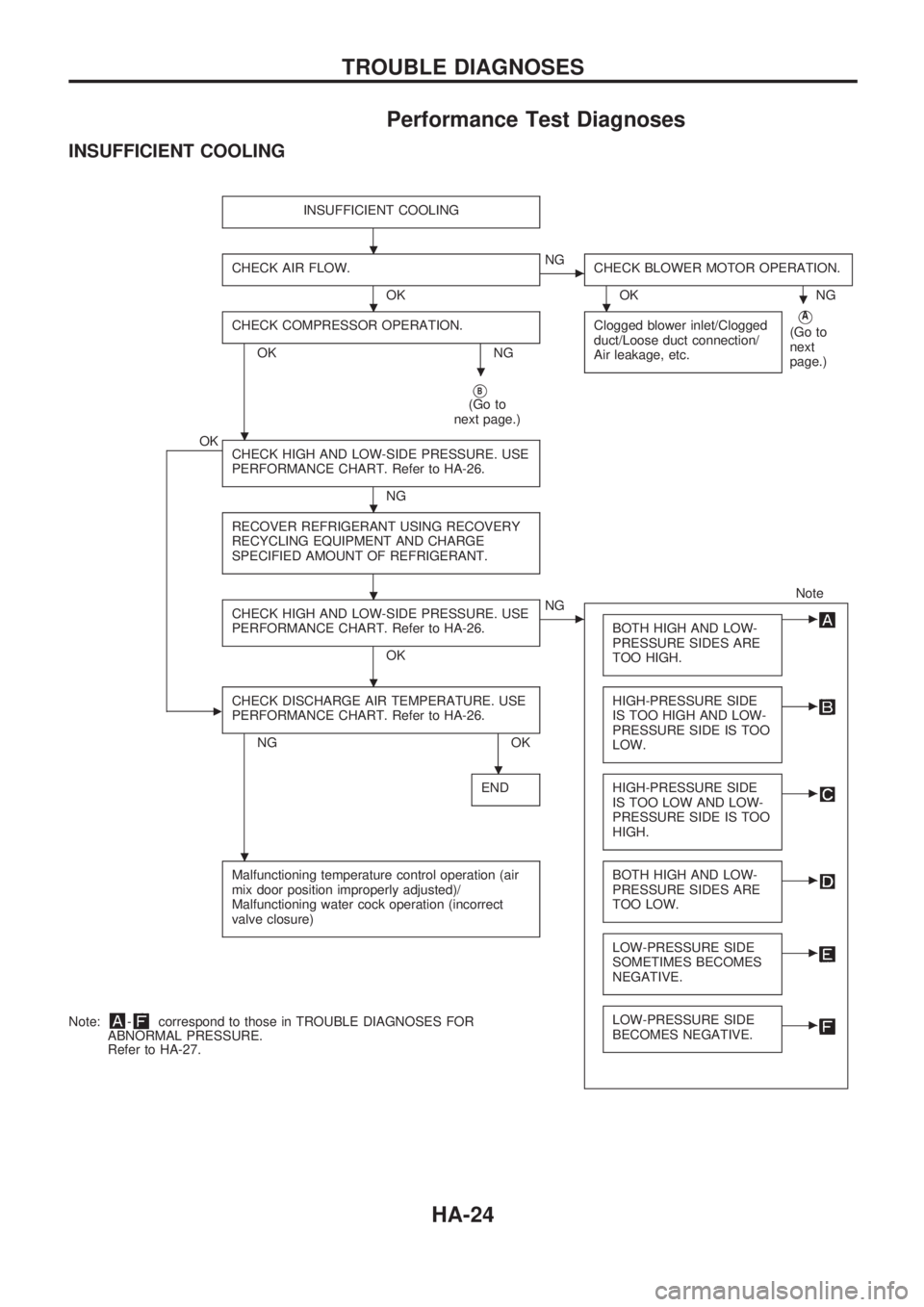
Performance Test Diagnoses
INSUFFICIENT COOLING
INSUFFICIENT COOLING
CHECK AIR FLOW.
OK
cNG
CHECK BLOWER MOTOR OPERATION.
OK NG
CHECK COMPRESSOR OPERATION.
OK NGClogged blower inlet/Clogged
duct/Loose duct connection/
Air leakage, etc.
VA
(Go to
next
page.)
VB(Go to
next page.)
OK
CHECK HIGH AND LOW-SIDE PRESSURE. USE
PERFORMANCE CHART. Refer to HA-26.
NG
RECOVER REFRIGERANT USING RECOVERY
RECYCLING EQUIPMENT AND CHARGE
SPECIFIED AMOUNT OF REFRIGERANT.
Note
CHECK HIGH AND LOW-SIDE PRESSURE. USE
PERFORMANCE CHART. Refer to HA-26.
OK
cNG
BOTH HIGH AND LOW-
PRESSURE SIDES ARE
TOO HIGH.c
cCHECK DISCHARGE AIR TEMPERATURE. USE
PERFORMANCE CHART. Refer to HA-26.
NG OKHIGH-PRESSURE SIDE
IS TOO HIGH AND LOW-
PRESSURE SIDE IS TOO
LOW.
c
ENDHIGH-PRESSURE SIDE
IS TOO LOW AND LOW-
PRESSURE SIDE IS TOO
HIGH.c
Malfunctioning temperature control operation (air
mix door position improperly adjusted)/
Malfunctioning water cock operation (incorrect
valve closure)BOTH HIGH AND LOW-
PRESSURE SIDES ARE
TOO LOW.c
LOW-PRESSURE SIDE
SOMETIMES BECOMES
NEGATIVE.c
LOW-PRESSURE SIDE
BECOMES NEGATIVE.cNote:-correspond to those in TROUBLE DIAGNOSES FOR
ABNORMAL PRESSURE.
Refer to HA-27.
.
...
.
.
.
.
.
.
.
TROUBLE DIAGNOSES
HA-24
Page 896 of 1659
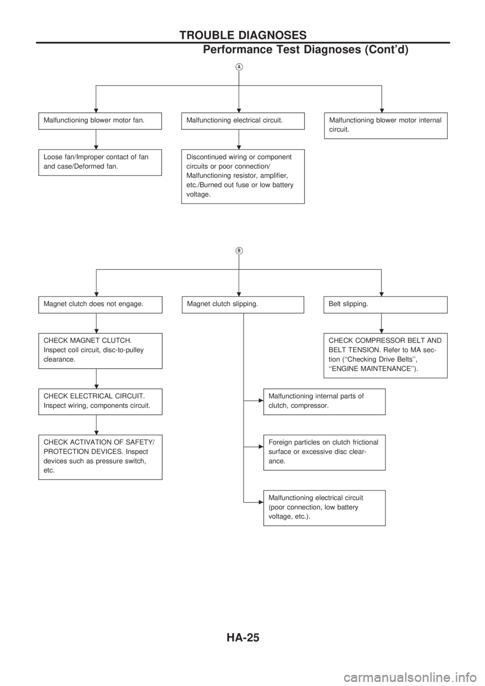
VA
Malfunctioning blower motor fan.Malfunctioning electrical circuit.Malfunctioning blower motor internal
circuit.
Loose fan/Improper contact of fan
and case/Deformed fan.Discontinued wiring or component
circuits or poor connection/
Malfunctioning resistor, amplifier,
etc./Burned out fuse or low battery
voltage.
VB
Magnet clutch does not engage.Magnet clutch slipping.Belt slipping.
CHECK MAGNET CLUTCH.
Inspect coil circuit, disc-to-pulley
clearance.CHECK COMPRESSOR BELT AND
BELT TENSION. Refer to MA sec-
tion (``Checking Drive Belts'',
``ENGINE MAINTENANCE'').
CHECK ELECTRICAL CIRCUIT.
Inspect wiring, components circuit.cMalfunctioning internal parts of
clutch, compressor.
CHECK ACTIVATION OF SAFETY/
PROTECTION DEVICES. Inspect
devices such as pressure switch,
etc.cForeign particles on clutch frictional
surface or excessive disc clear-
ance.
cMalfunctioning electrical circuit
(poor connection, low battery
voltage, etc.).
...
..
...
..
.
.
TROUBLE DIAGNOSES
Performance Test Diagnoses (Cont'd)
HA-25
Page 897 of 1659
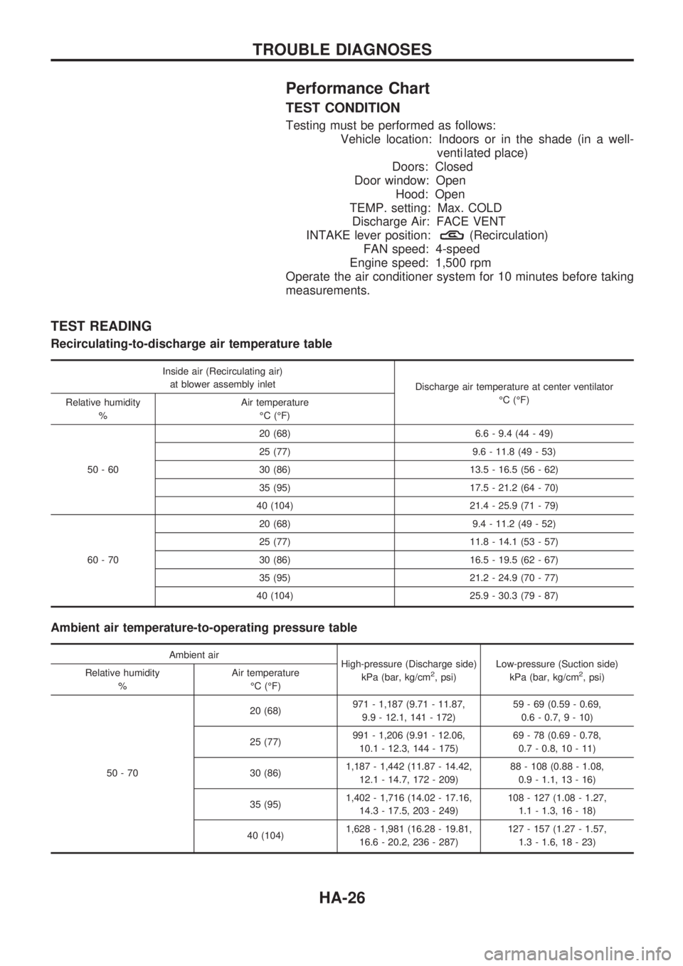
Performance Chart
TEST CONDITION
Testing must be performed as follows:
Vehicle location: Indoors or in the shade (in a well-
venti lated place)
Doors: Closed
Door window: Open
Hood: Open
TEMP. setting: Max. COLD
Discharge Air: FACE VENT
INTAKE lever position:
(Recirculation)
FAN speed: 4-speed
Engine speed: 1,500 rpm
Operate the air conditioner system for 10 minutes before taking
measurements.
TEST READING
Recirculating-to-discharge air temperature table
Inside air (Recirculating air)
at blower assembly inlet
Discharge air temperature at center ventilator
ÉC (ÉF)
Relative humidity
%Air temperature
ÉC (ÉF)
50-6020 (68) 6.6 - 9.4 (44 - 49)
25 (77) 9.6 - 11.8 (49 - 53)
30 (86) 13.5 - 16.5 (56 - 62)
35 (95) 17.5 - 21.2 (64 - 70)
40 (104) 21.4 - 25.9 (71 - 79)
60-7020 (68) 9.4 - 11.2 (49 - 52)
25 (77) 11.8 - 14.1 (53 - 57)
30 (86) 16.5 - 19.5 (62 - 67)
35 (95) 21.2 - 24.9 (70 - 77)
40 (104) 25.9 - 30.3 (79 - 87)
Ambient air temperature-to-operating pressure table
Ambient air
High-pressure (Discharge side)
kPa (bar, kg/cm
2, psi)Low-pressure (Suction side)
kPa (bar, kg/cm2, psi) Relative humidity
%Air temperature
ÉC (ÉF)
50-7020 (68)971 - 1,187 (9.71 - 11.87,
9.9 - 12.1, 141 - 172)59 - 69 (0.59 - 0.69,
0.6 - 0.7, 9 - 10)
25 (77)991 - 1,206 (9.91 - 12.06,
10.1 - 12.3, 144 - 175)69 - 78 (0.69 - 0.78,
0.7 - 0.8, 10 - 11)
30 (86)1,187 - 1,442 (11.87 - 14.42,
12.1 - 14.7, 172 - 209)88 - 108 (0.88 - 1.08,
0.9 - 1.1, 13 - 16)
35 (95)1,402 - 1,716 (14.02 - 17.16,
14.3 - 17.5, 203 - 249)108 - 127 (1.08 - 1.27,
1.1 - 1.3, 16 - 18)
40 (104)1,628 - 1,981 (16.28 - 19.81,
16.6 - 20.2, 236 - 287)127 - 157 (1.27 - 1.57,
1.3 - 1.6, 18 - 23)
TROUBLE DIAGNOSES
HA-26
Page 898 of 1659
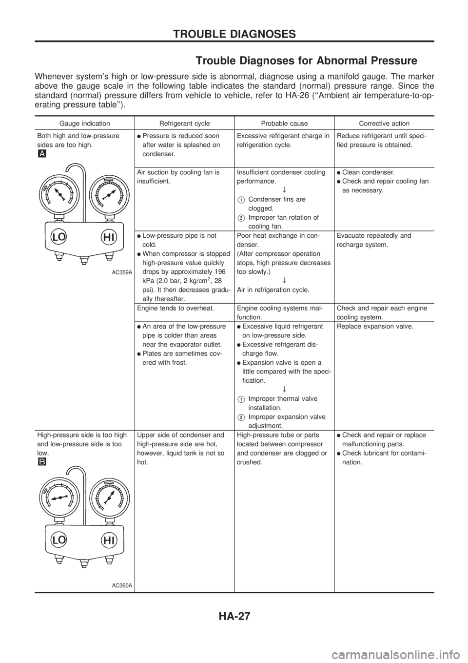
Trouble Diagnoses for Abnormal Pressure
Whenever system's high or low-pressure side is abnormal, diagnose using a manifold gauge. The marker
above the gauge scale in the following table indicates the standard (normal) pressure range. Since the
standard (normal) pressure differs from vehicle to vehicle, refer to HA-26 (``Ambient air temperature-to-op-
erating pressure table'').
Gauge indication Refrigerant cycle Probable cause Corrective action
Both high and low-pressure
sides are too high.
AC359A
lPressure is reduced soon
after water is splashed on
condenser.Excessive refrigerant charge in
refrigeration cycle.Reduce refrigerant until speci-
fied pressure is obtained.
Air suction by cooling fan is
insufficient.Insufficient condenser cooling
performance.
¯
V1Condenser fins are
clogged.
V2Improper fan rotation of
cooling fan.
lClean condenser.
lCheck and repair cooling fan
as necessary.
lLow-pressure pipe is not
cold.
lWhen compressor is stopped
high-pressure value quickly
drops by approximately 196
kPa (2.0 bar, 2 kg/cm
2,28
psi). It then decreases gradu-
ally thereafter.Poor heat exchange in con-
denser.
(After compressor operation
stops, high pressure decreases
too slowly.)
¯
Air in refrigeration cycle.Evacuate repeatedly and
recharge system.
Engine tends to overheat. Engine cooling systems mal-
function.Check and repair each engine
cooling system.
lAn area of the low-pressure
pipe is colder than areas
near the evaporator outlet.
lPlates are sometimes cov-
ered with frost.
lExcessive liquid refrigerant
on low-pressure side.
lExcessive refrigerant dis-
charge flow.
lExpansion valve is open a
little compared with the speci-
fication.
¯
V1Improper thermal valve
installation.
V2Improper expansion valve
adjustment.Replace expansion valve.
High-pressure side is too high
and low-pressure side is too
low.
AC360A
Upper side of condenser and
high-pressure side are hot,
however, liquid tank is not so
hot.High-pressure tube or parts
located between compressor
and condenser are clogged or
crushed.lCheck and repair or replace
malfunctioning parts.
lCheck lubricant for contami-
nation.
TROUBLE DIAGNOSES
HA-27
Page 899 of 1659
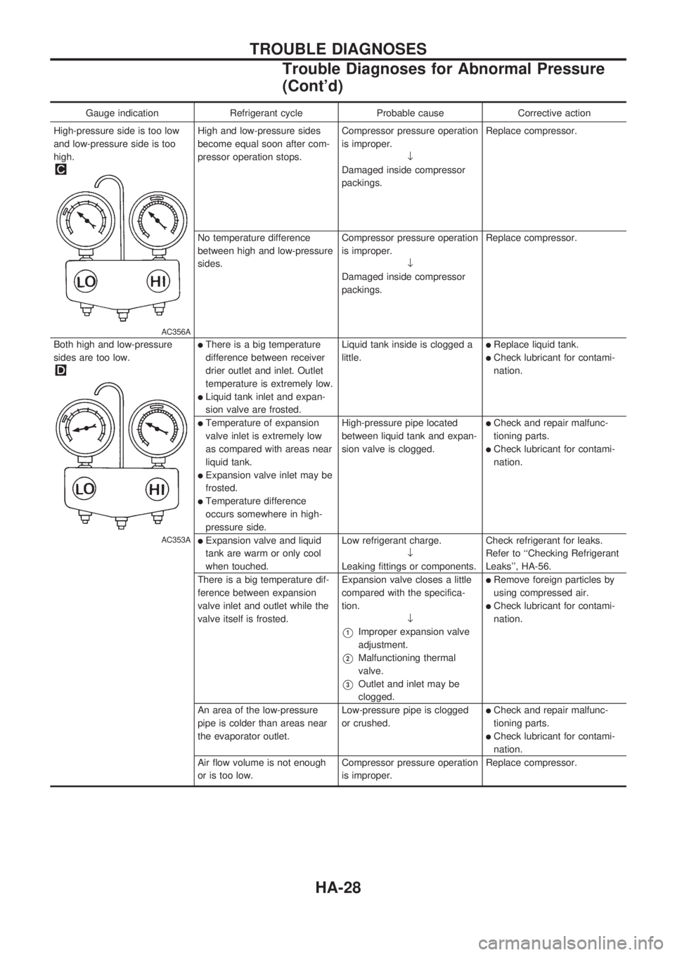
Gauge indication Refrigerant cycle Probable cause Corrective action
High-pressure side is too low
and low-pressure side is too
high.
AC356A
High and low-pressure sides
become equal soon after com-
pressor operation stops.Compressor pressure operation
is improper.
¯
Damaged inside compressor
packings.Replace compressor.
No temperature difference
between high and low-pressure
sides.Compressor pressure operation
is improper.
¯
Damaged inside compressor
packings.Replace compressor.
Both high and low-pressure
sides are too low.
AC353A
lThere is a big temperature
difference between receiver
drier outlet and inlet. Outlet
temperature is extremely low.
lLiquid tank inlet and expan-
sion valve are frosted.Liquid tank inside is clogged a
little.
lReplace liquid tank.
lCheck lubricant for contami-
nation.
lTemperature of expansion
valve inlet is extremely low
as compared with areas near
liquid tank.
lExpansion valve inlet may be
frosted.
lTemperature difference
occurs somewhere in high-
pressure side.High-pressure pipe located
between liquid tank and expan-
sion valve is clogged.
lCheck and repair malfunc-
tioning parts.
lCheck lubricant for contami-
nation.
lExpansion valve and liquid
tank are warm or only cool
when touched.Low refrigerant charge.
¯
Leaking fittings or components.Check refrigerant for leaks.
Refer to ``Checking Refrigerant
Leaks'', HA-56.
There is a big temperature dif-
ference between expansion
valve inlet and outlet while the
valve itself is frosted.Expansion valve closes a little
compared with the specifica-
tion.
¯
V1Improper expansion valve
adjustment.
V2Malfunctioning thermal
valve.
V3Outlet and inlet may be
clogged.
lRemove foreign particles by
using compressed air.
lCheck lubricant for contami-
nation.
An area of the low-pressure
pipe is colder than areas near
the evaporator outlet.Low-pressure pipe is clogged
or crushed.
lCheck and repair malfunc-
tioning parts.
lCheck lubricant for contami-
nation.
Air flow volume is not enough
or is too low.Compressor pressure operation
is improper.Replace compressor.
TROUBLE DIAGNOSES
Trouble Diagnoses for Abnormal Pressure
(Cont'd)
HA-28
Page 900 of 1659
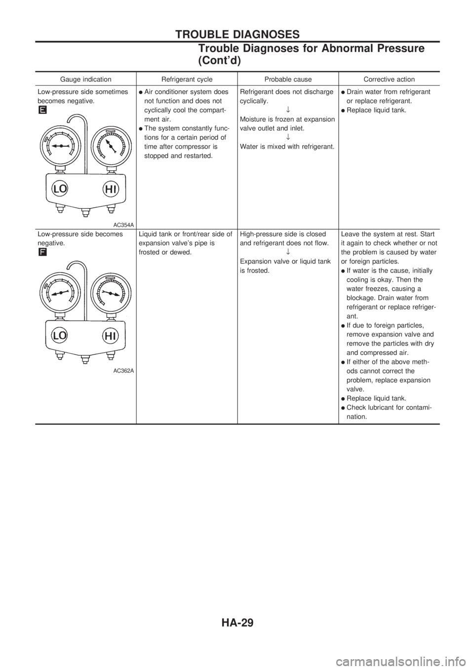
Gauge indication Refrigerant cycle Probable cause Corrective action
Low-pressure side sometimes
becomes negative.
AC354A
lAir conditioner system does
not function and does not
cyclically cool the compart-
ment air.
lThe system constantly func-
tions for a certain period of
time after compressor is
stopped and restarted.Refrigerant does not discharge
cyclically.
¯
Moisture is frozen at expansion
valve outlet and inlet.
¯
Water is mixed with refrigerant.
lDrain water from refrigerant
or replace refrigerant.
lReplace liquid tank.
Low-pressure side becomes
negative.
AC362A
Liquid tank or front/rear side of
expansion valve's pipe is
frosted or dewed.High-pressure side is closed
and refrigerant does not flow.
¯
Expansion valve or liquid tank
is frosted.Leave the system at rest. Start
it again to check whether or not
the problem is caused by water
or foreign particles.
lIf water is the cause, initially
cooling is okay. Then the
water freezes, causing a
blockage. Drain water from
refrigerant or replace refriger-
ant.
lIf due to foreign particles,
remove expansion valve and
remove the particles with dry
and compressed air.
lIf either of the above meth-
ods cannot correct the
problem, replace expansion
valve.
lReplace liquid tank.
lCheck lubricant for contami-
nation.
TROUBLE DIAGNOSES
Trouble Diagnoses for Abnormal Pressure
(Cont'd)
HA-29