NISSAN PICK-UP 1998 Repair Manual
Manufacturer: NISSAN, Model Year: 1998, Model line: PICK-UP, Model: NISSAN PICK-UP 1998Pages: 1659, PDF Size: 53.39 MB
Page 911 of 1659
VA
CHECK TRIPLE-PRESSURE SWITCH.
Refer to HA-44.
OK
cNG
Check refrigerant charge
amount.
OK
Note
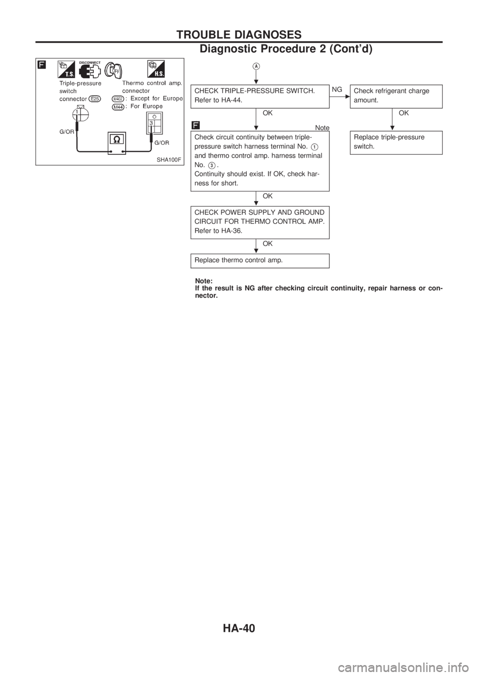
Check circuit continuity between triple-
pressure switch harness terminal No.
V1
and thermo control amp. harness terminal
No.
V3.
Continuity should exist. If OK, check har-
ness for short.
OKReplace triple-pressure
switch.
CHECK POWER SUPPLY AND GROUND
CIRCUIT FOR THERMO CONTROL AMP.
Refer to HA-36.
OK
Replace thermo control amp.
Note:
If the result is NG after checking circuit continuity, repair harness or con-
nector.
SHA100F
.
..
.
.
TROUBLE DIAGNOSES
Diagnostic Procedure 2 (Cont'd)
HA-40
Page 912 of 1659
FOR KA ENGINE MODELS
SYMPTOM: Magnet clutch does not engage when A/C
switch and fan switch are ON.
lPerform PRELIMINARY CHECK 1 before referring to the
following flow chart.
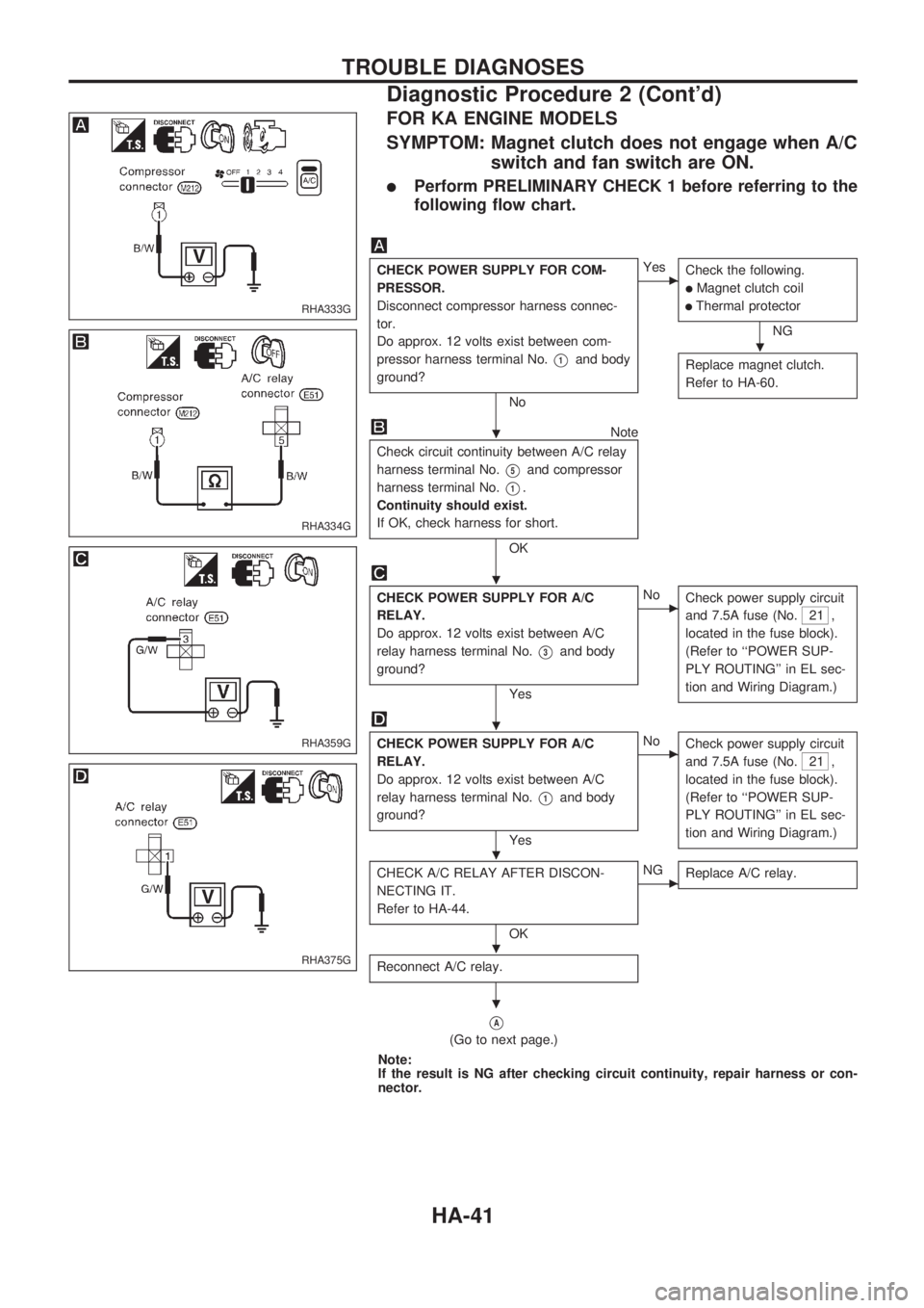
CHECK POWER SUPPLY FOR COM-
PRESSOR.
Disconnect compressor harness connec-
tor.
Do approx. 12 volts exist between com-
pressor harness terminal No.
V1and body
ground?
No
cYes
Check the following.
lMagnet clutch coil
lThermal protector
NG
Replace magnet clutch.
Refer to HA-60.
Note
Check circuit continuity between A/C relay
harness terminal No.
V5and compressor
harness terminal No.
V1.
Continuity should exist.
If OK, check harness for short.
OK
CHECK POWER SUPPLY FOR A/C
RELAY.
Do approx. 12 volts exist between A/C
relay harness terminal No.
V3and body
ground?
Yes
cNo
Check power supply circuit
and 7.5A fuse (No.
21 ,
located in the fuse block).
(Refer to ``POWER SUP-
PLY ROUTING'' in EL sec-
tion and Wiring Diagram.)
CHECK POWER SUPPLY FOR A/C
RELAY.
Do approx. 12 volts exist between A/C
relay harness terminal No.
V1and body
ground?
Yes
cNo
Check power supply circuit
and 7.5A fuse (No.
21 ,
located in the fuse block).
(Refer to ``POWER SUP-
PLY ROUTING'' in EL sec-
tion and Wiring Diagram.)
CHECK A/C RELAY AFTER DISCON-
NECTING IT.
Refer to HA-44.
OK
cNG
Replace A/C relay.
Reconnect A/C relay.
VA
(Go to next page.)
Note:
If the result is NG after checking circuit continuity, repair harness or con-
nector.
RHA333G
RHA334G
RHA359G
RHA375G
.
.
.
.
.
.
.
TROUBLE DIAGNOSES
Diagnostic Procedure 2 (Cont'd)
HA-41
Page 913 of 1659
VA
Note
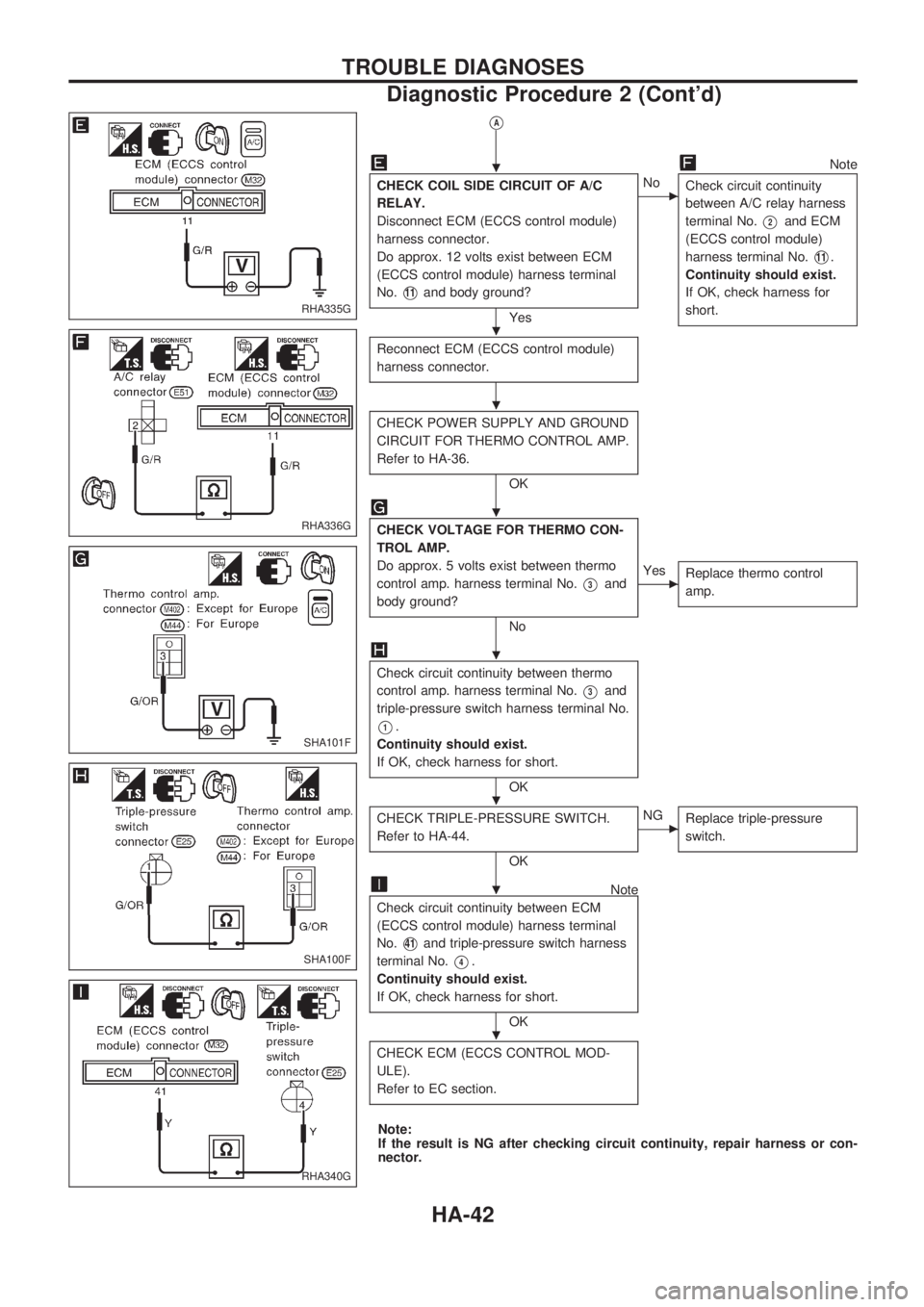
CHECK COIL SIDE CIRCUIT OF A/C
RELAY.
Disconnect ECM (ECCS control module)
harness connector.
Do approx. 12 volts exist between ECM
(ECCS control module) harness terminal
No.
V11and body ground?
Yes
cNo
Check circuit continuity
between A/C relay harness
terminal No.
V2and ECM
(ECCS control module)
harness terminal No.
V11.
Continuity should exist.
If OK, check harness for
short.
Reconnect ECM (ECCS control module)
harness connector.
CHECK POWER SUPPLY AND GROUND
CIRCUIT FOR THERMO CONTROL AMP.
Refer to HA-36.
OK
CHECK VOLTAGE FOR THERMO CON-
TROL AMP.
Do approx. 5 volts exist between thermo
control amp. harness terminal No.
V3and
body ground?
No
cYes
Replace thermo control
amp.
Check circuit continuity between thermo
control amp. harness terminal No.
V3and
triple-pressure switch harness terminal No.
V1.
Continuity should exist.
If OK, check harness for short.
OK
CHECK TRIPLE-PRESSURE SWITCH.
Refer to HA-44.
OK
cNG
Replace triple-pressure
switch.
Note
Check circuit continuity between ECM
(ECCS control module) harness terminal
No.
V41and triple-pressure switch harness
terminal No.
V4.
Continuity should exist.
If OK, check harness for short.
OK
CHECK ECM (ECCS CONTROL MOD-
ULE).
Refer to EC section.
Note:
If the result is NG after checking circuit continuity, repair harness or con-
nector.
RHA335G
RHA336G
SHA101F
SHA100F
RHA340G
.
.
.
.
.
.
.
.
TROUBLE DIAGNOSES
Diagnostic Procedure 2 (Cont'd)
HA-42
Page 914 of 1659
Electrical Components Inspection
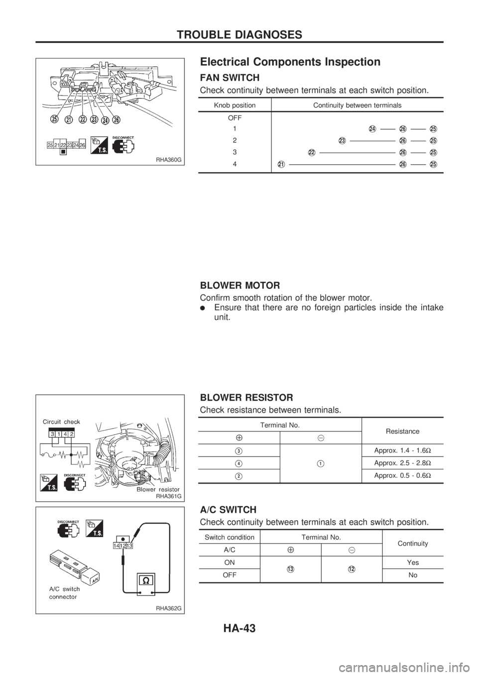
FAN SWITCH
Check continuity between terminals at each switch position.
Knob position Continuity between terminals
OFF
1
V24V26V25
2V23V26V25
3V22V26V25
4V21V26V25
BLOWER MOTOR
Confirm smooth rotation of the blower motor.
lEnsure that there are no foreign particles inside the intake
unit.
BLOWER RESISTOR
Check resistance between terminals.
Terminal No.
Resistance
Å@
V3
V1
Approx. 1.4 - 1.6W
V4Approx. 2.5 - 2.8W
V2Approx. 0.5 - 0.6W
A/C SWITCH
Check continuity between terminals at each switch position.
Switch condition Terminal No.
Continuity
A/C
Å@
ON
V13V12Yes
OFF No
RHA360G
RHA361G
RHA362G
TROUBLE DIAGNOSES
HA-43
Page 915 of 1659
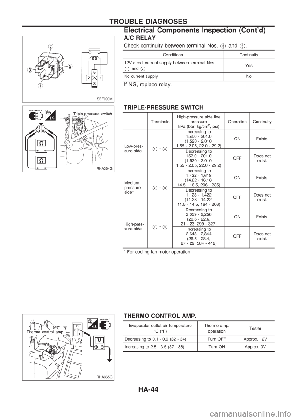
A/C RELAY
Check continuity between terminal Nos.V3andV5.
Conditions Continuity
12V direct current supply between terminal Nos.
V1andV2Yes
No current supply No
If NG, replace relay.
TRIPLE-PRESSURE SWITCH
TerminalsHigh-pressure side line
pressure
kPa (bar, kg/cm2, psi)Operation Continuity
Low-pres-
sure side
V1-V4
Increasing to
152.0 - 201.0
(1.520 - 2.010,
1.55 - 2.05, 22.0 - 29.2)ON Exists.
Decreasing to
152.0 - 201.0
(1.520 - 2.010,
1.55 - 2.05, 22.0 - 29.2)OFFDoes not
exist.
Medium-
pressure
side*
V2-V3
Increasing to
1,422 - 1,618
(14.22 - 16.18,
14.5 - 16.5, 206 - 235)ON Exists.
Decreasing to
1,128 - 1,422
(11.28 - 14.22,
11.5 - 14.5, 164 - 206)OFFDoes not
exist.
High-pres-
sure side
V1-V4
Decreasing to
2,059 - 2,256
(20.6 - 22.6,
21 - 23, 299 - 327)ON Exists.
Increasing to
2,648 - 2,844
(26.5 - 28.4,
27 - 29, 384 - 412)OFFDoes not
exist.
* For cooling fan motor operation
THERMO CONTROL AMP.
Evaporator outlet air temperature
ÉC (ÉF)Thermo amp.
operationTester
Decreasing to 0.1 - 0.9 (32 - 34) Turn OFF Approx. 12V
Increasing to 2.5 - 3.5 (37 - 38) Turn ON Approx. 0V
SEF090M
RHA364G
RHA365G
TROUBLE DIAGNOSES
Electrical Components Inspection (Cont'd)
HA-44
Page 916 of 1659
THERMAL PROTECTOR (For DKV-14C)
Temperature of compressor
ÉC (ÉF)Operation
Increasing to approx. 145 - 155 (293 - 311) Turn OFF
Decreasing to approx. 130 - 140 (266 - 284) Turn ON
Control Linkage Adjustment
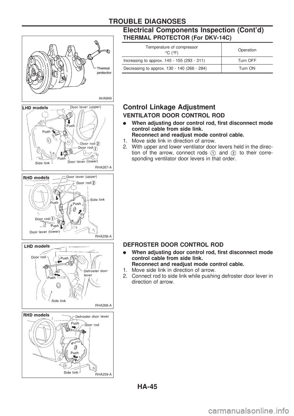
VENTILATOR DOOR CONTROL ROD
lWhen adjusting door control rod, first disconnect mode
control cable from side link.
Reconnect and readjust mode control cable.
1. Move side link in direction of arrow.
2. With upper and lower ventilator door levers held in the direc-
tion of the arrow, connect rods
V1andV2to their corre-
sponding ventilator door levers in that order.
DEFROSTER DOOR CONTROL ROD
lWhen adjusting door control rod, first disconnect mode
control cable from side link.
Reconnect and readjust mode control cable.
1. Move side link in direction of arrow.
2. Connect rod to side link while pushing defroster door lever in
direction of arrow.
AHA849
RHA267-A
RHA258-A
RHA268-A
RHA259-A
TROUBLE DIAGNOSES
Electrical Components Inspection (Cont'd)
HA-45
Page 917 of 1659
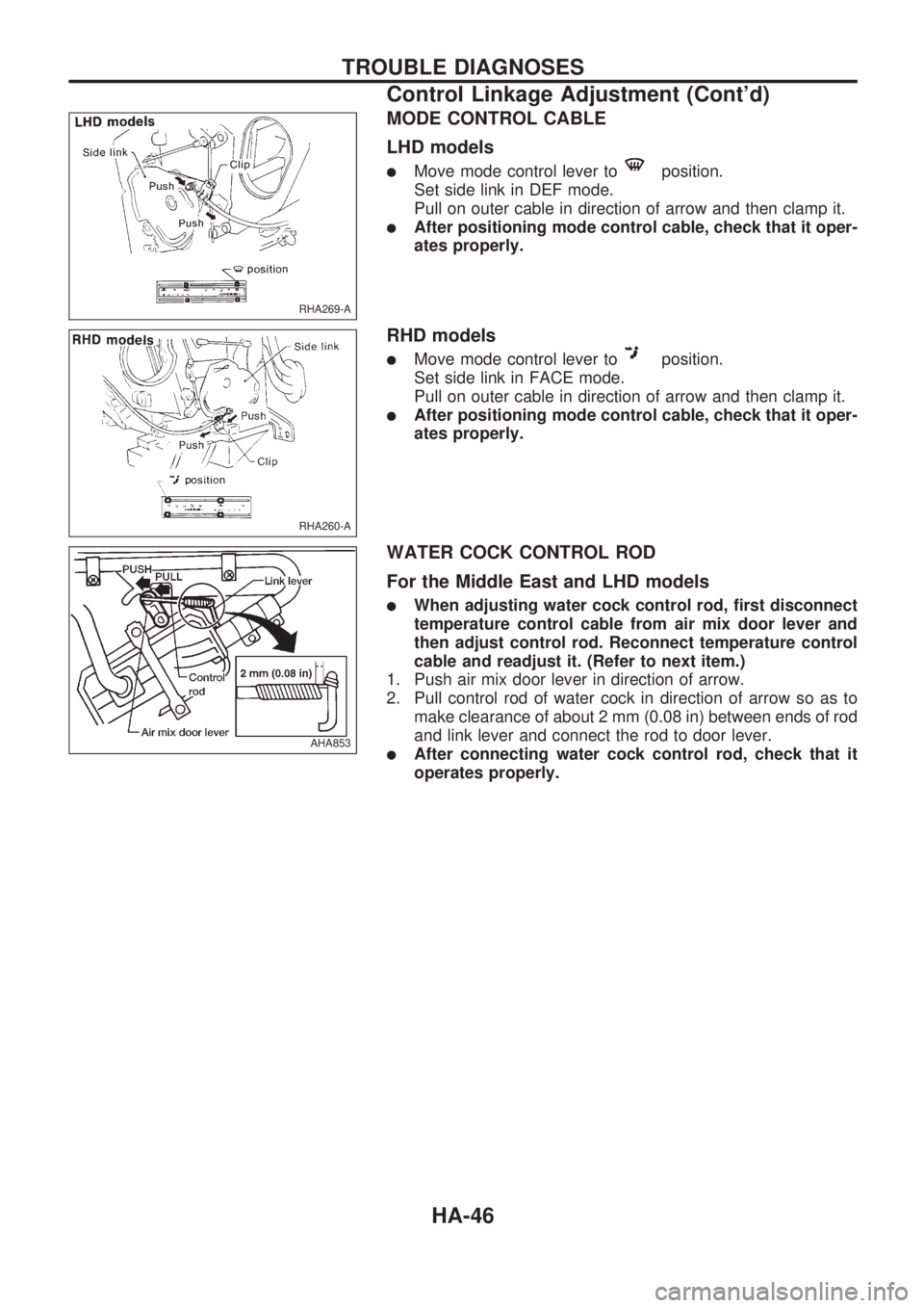
MODE CONTROL CABLE
LHD models
lMove mode control lever toposition.
Set side link in DEF mode.
Pull on outer cable in direction of arrow and then clamp it.
lAfter positioning mode control cable, check that it oper-
ates properly.
RHD models
lMove mode control lever toposition.
Set side link in FACE mode.
Pull on outer cable in direction of arrow and then clamp it.
lAfter positioning mode control cable, check that it oper-
ates properly.
WATER COCK CONTROL ROD
For the Middle East and LHD models
lWhen adjusting water cock control rod, first disconnect
temperature control cable from air mix door lever and
then adjust control rod. Reconnect temperature control
cable and readjust it. (Refer to next item.)
1. Push air mix door lever in direction of arrow.
2. Pull control rod of water cock in direction of arrow so as to
make clearance of about 2 mm (0.08 in) between ends of rod
and link lever and connect the rod to door lever.
lAfter connecting water cock control rod, check that it
operates properly.
RHA269-A
RHA260-A
AHA853
TROUBLE DIAGNOSES
Control Linkage Adjustment (Cont'd)
HA-46
Page 918 of 1659
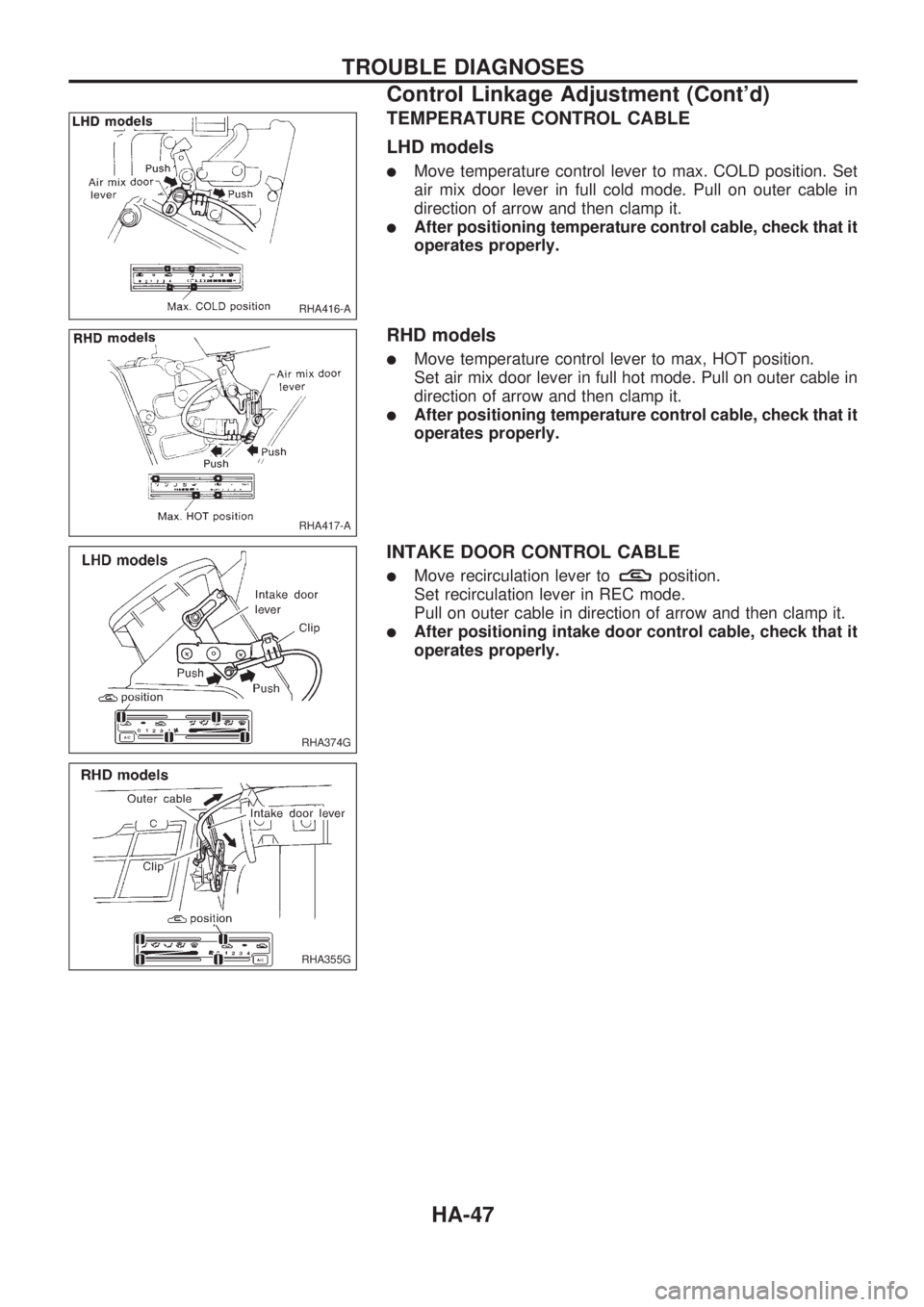
TEMPERATURE CONTROL CABLE
LHD models
lMove temperature control lever to max. COLD position. Set
air mix door lever in full cold mode. Pull on outer cable in
direction of arrow and then clamp it.
lAfter positioning temperature control cable, check that it
operates properly.
RHD models
lMove temperature control lever to max, HOT position.
Set air mix door lever in full hot mode. Pull on outer cable in
direction of arrow and then clamp it.
lAfter positioning temperature control cable, check that it
operates properly.
INTAKE DOOR CONTROL CABLE
lMove recirculation lever toposition.
Set recirculation lever in REC mode.
Pull on outer cable in direction of arrow and then clamp it.
lAfter positioning intake door control cable, check that it
operates properly.
RHA416-A
RHA417-A
RHA374G
RHA355G
TROUBLE DIAGNOSES
Control Linkage Adjustment (Cont'd)
HA-47
Page 919 of 1659
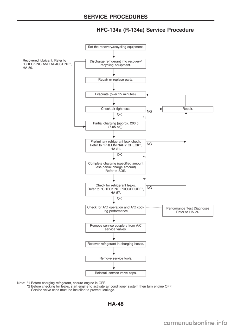
HFC-134a (R-134a) Service Procedure
Set the recovery/recycling equipment.
Recovered lubricant. Refer to
``CHECKING AND ADJUSTING'',
HA-50.
c
Discharge refrigerant into recovery/
recycling equipment.
Repair or replace parts.
Evacuate (over 25 minutes).b
Check air tightness.
OK
*1
cNGRepair.m
Partial charging [approx. 200 g
(7.05 oz)].
Preliminary refrigerant leak check.
Refer to ``PRELIMINARY CHECK'',
HA-21.
OK
*1
cNG
Complete charging (specified amount
less partial charge amount)
Refer to SDS.
*2
Check for refrigerant leaks.
Refer to ``CHECKING PROCEDURE'',
HA-57.
OK
NG
Check for A/C operation and A/C cool-
ing performance..................
Performance Test Diagnoses
Refer to HA-24.
Remove service couplers from A/C
service valves.
Recover refrigerant in charging hoses.
Remove service tools.
Reinstall service valve caps.
Note: *1 Before charging refrigerant, ensure engine is OFF.
*2 Before checking for leaks, start engine to activate air conditioner system then turn engine OFF.
Service valve caps must be installed to prevent leakage.
.
.
.
.
.
.
.
.
.
.
.
.
.
SERVICE PROCEDURES
HA-48
Page 920 of 1659
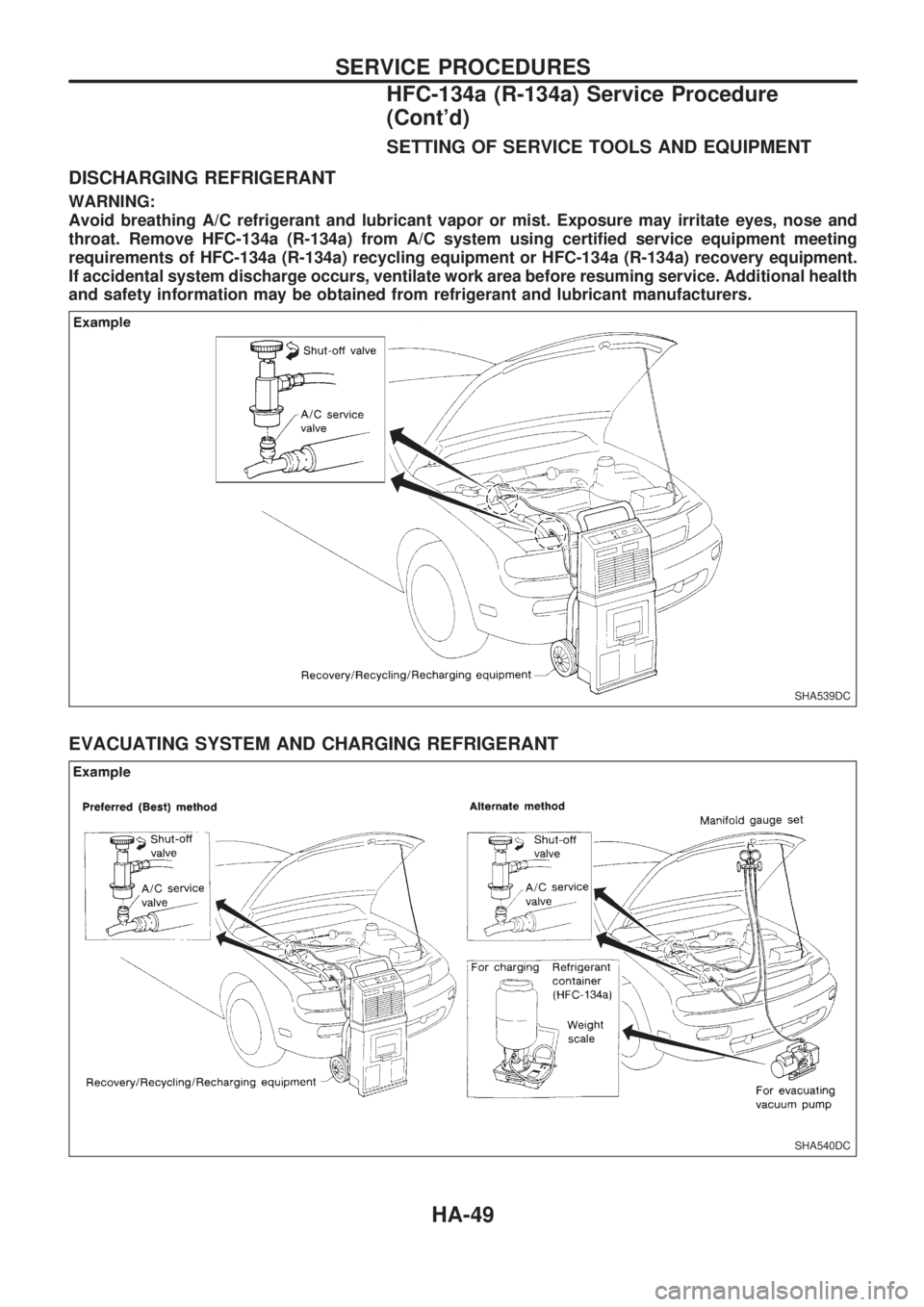
SETTING OF SERVICE TOOLS AND EQUIPMENT
DISCHARGING REFRIGERANT
WARNING:
Avoid breathing A/C refrigerant and lubricant vapor or mist. Exposure may irritate eyes, nose and
throat. Remove HFC-134a (R-134a) from A/C system using certified service equipment meeting
requirements of HFC-134a (R-134a) recycling equipment or HFC-134a (R-134a) recovery equipment.
If accidental system discharge occurs, ventilate work area before resuming service. Additional health
and safety information may be obtained from refrigerant and lubricant manufacturers.
EVACUATING SYSTEM AND CHARGING REFRIGERANT
SHA539DC
SHA540DC
SERVICE PROCEDURES
HFC-134a (R-134a) Service Procedure
(Cont'd)
HA-49