NISSAN PICK-UP 1998 Repair Manual
Manufacturer: NISSAN, Model Year: 1998, Model line: PICK-UP, Model: NISSAN PICK-UP 1998Pages: 1659, PDF Size: 53.39 MB
Page 931 of 1659
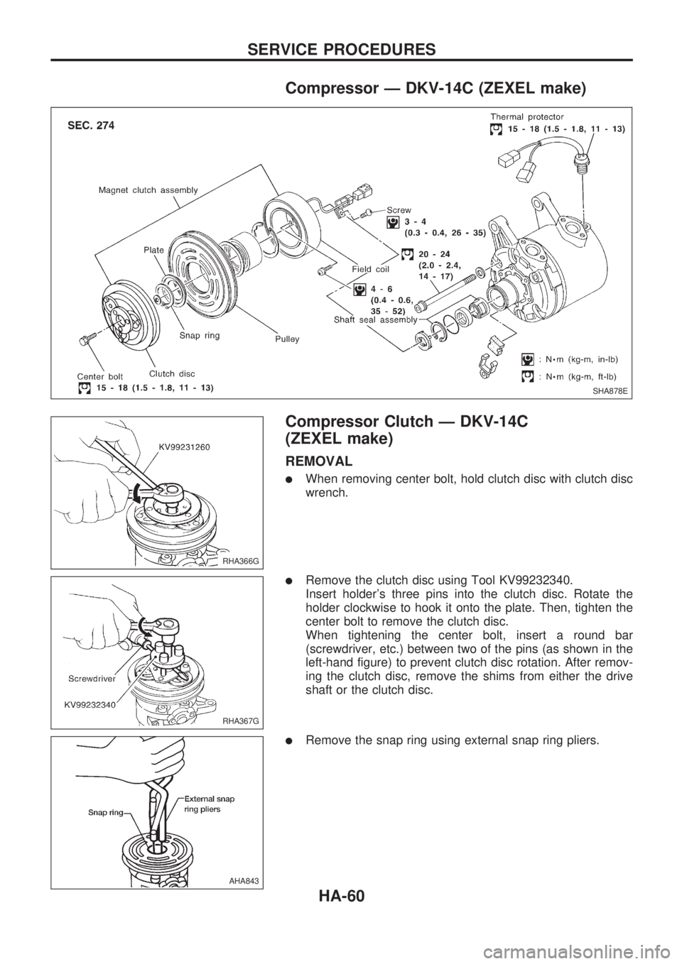
Compressor Ð DKV-14C (ZEXEL make)
Compressor Clutch Ð DKV-14C
(ZEXEL make)
REMOVAL
lWhen removing center bolt, hold clutch disc with clutch disc
wrench.
lRemove the clutch disc using Tool KV99232340.
Insert holder's three pins into the clutch disc. Rotate the
holder clockwise to hook it onto the plate. Then, tighten the
center bolt to remove the clutch disc.
When tightening the center bolt, insert a round bar
(screwdriver, etc.) between two of the pins (as shown in the
left-hand figure) to prevent clutch disc rotation. After remov-
ing the clutch disc, remove the shims from either the drive
shaft or the clutch disc.
lRemove the snap ring using external snap ring pliers.
SHA878E
RHA366G
RHA367G
AHA843
SERVICE PROCEDURES
HA-60
Page 932 of 1659
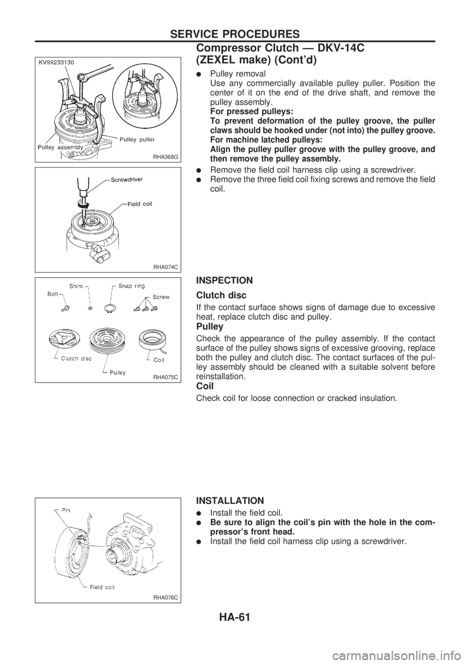
lPulley removal
Use any commercially available pulley puller. Position the
center of it on the end of the drive shaft, and remove the
pulley assembly.
For pressed pulleys:
To prevent deformation of the pulley groove, the puller
claws should be hooked under (not into) the pulley groove.
For machine latched pulleys:
Align the pulley puller groove with the pulley groove, and
then remove the pulley assembly.
lRemove the field coil harness clip using a screwdriver.
lRemove the three field coil fixing screws and remove the field
coil.
INSPECTION
Clutch disc
If the contact surface shows signs of damage due to excessive
heat, replace clutch disc and pulley.
Pulley
Check the appearance of the pulley assembly. If the contact
surface of the pulley shows signs of excessive grooving, replace
both the pulley and clutch disc. The contact surfaces of the pul-
ley assembly should be cleaned with a suitable solvent before
reinstallation.
Coil
Check coil for loose connection or cracked insulation.
INSTALLATION
lInstall the field coil.
lBe sure to align the coil's pin with the hole in the com-
pressor's front head.
lInstall the field coil harness clip using a screwdriver.
RHA368G
RHA074C
RHA075C
RHA076C
SERVICE PROCEDURES
Compressor Clutch Ð DKV-14C
(ZEXEL make) (Cont'd)
HA-61
Page 933 of 1659
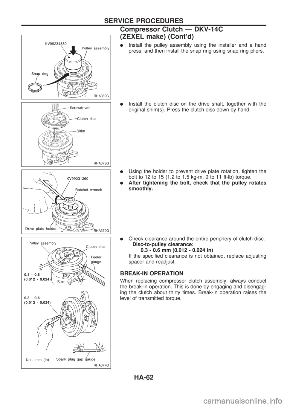
lInstall the pulley assembly using the installer and a hand
press, and then install the snap ring using snap ring pliers.
lInstall the clutch disc on the drive shaft, together with the
original shim(s). Press the clutch disc down by hand.
lUsing the holder to prevent drive plate rotation, tighten the
bolt to 12 to 15 (1.2 to 1.5 kg-m, 9 to 11 ft-lb) torque.
lAfter tightening the bolt, check that the pulley rotates
smoothly.
lCheck clearance around the entire periphery of clutch disc.
Disc-to-pulley clearance:
0.3 - 0.6 mm (0.012 - 0.024 in)
If the specified clearance is not obtained, replace adjusting
spacer and readjust.
BREAK-IN OPERATION
When replacing compressor clutch assembly, always conduct
the break-in operation. This is done by engaging and disengag-
ing the clutch about thirty times. Break-in operation raises the
level of transmitted torque.
RHA369G
RHA373G
RHA370G
RHA377G
SERVICE PROCEDURES
Compressor Clutch Ð DKV-14C
(ZEXEL make) (Cont'd)
HA-62
Page 934 of 1659
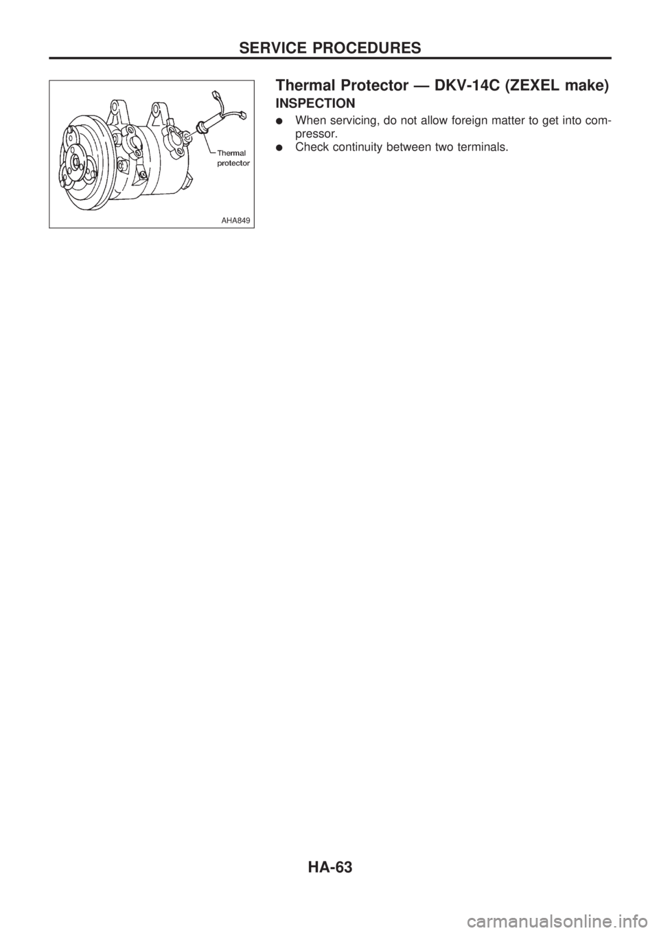
Thermal Protector Ð DKV-14C (ZEXEL make)
INSPECTION
lWhen servicing, do not allow foreign matter to get into com-
pressor.
lCheck continuity between two terminals.
AHA849
SERVICE PROCEDURES
HA-63
Page 935 of 1659
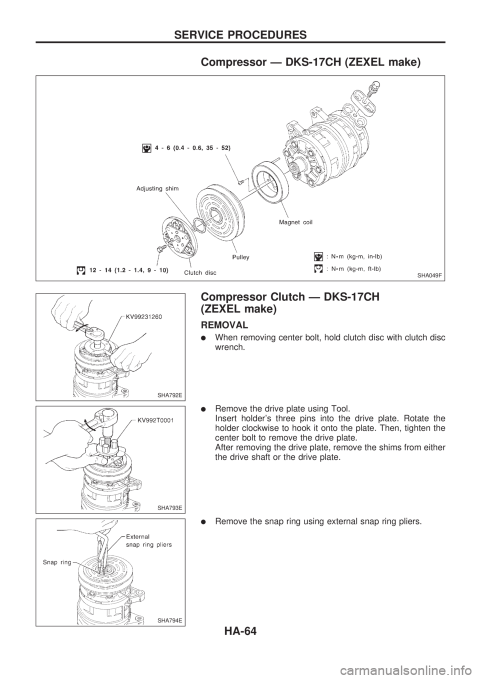
Compressor Ð DKS-17CH (ZEXEL make)
Compressor Clutch Ð DKS-17CH
(ZEXEL make)
REMOVAL
lWhen removing center bolt, hold clutch disc with clutch disc
wrench.
lRemove the drive plate using Tool.
Insert holder's three pins into the drive plate. Rotate the
holder clockwise to hook it onto the plate. Then, tighten the
center bolt to remove the drive plate.
After removing the drive plate, remove the shims from either
the drive shaft or the drive plate.
lRemove the snap ring using external snap ring pliers.
SHA049F
SHA792E
SHA793E
SHA794E
SERVICE PROCEDURES
HA-64
Page 936 of 1659
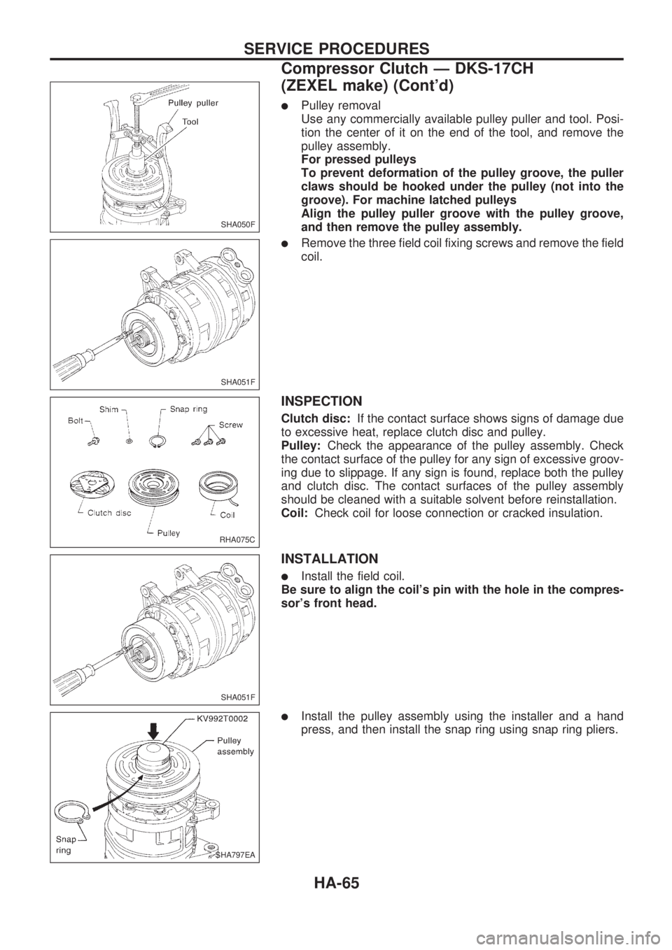
lPulley removal
Use any commercially available pulley puller and tool. Posi-
tion the center of it on the end of the tool, and remove the
pulley assembly.
For pressed pulleys
To prevent deformation of the pulley groove, the puller
claws should be hooked under the pulley (not into the
groove). For machine latched pulleys
Align the pulley puller groove with the pulley groove,
and then remove the pulley assembly.
lRemove the three field coil fixing screws and remove the field
coil.
INSPECTION
Clutch disc:If the contact surface shows signs of damage due
to excessive heat, replace clutch disc and pulley.
Pulley:Check the appearance of the pulley assembly. Check
the contact surface of the pulley for any sign of excessive groov-
ing due to slippage. If any sign is found, replace both the pulley
and clutch disc. The contact surfaces of the pulley assembly
should be cleaned with a suitable solvent before reinstallation.
Coil:Check coil for loose connection or cracked insulation.
INSTALLATION
lInstall the field coil.
Be sure to align the coil's pin with the hole in the compres-
sor's front head.
lInstall the pulley assembly using the installer and a hand
press, and then install the snap ring using snap ring pliers.
SHA050F
SHA051F
RHA075C
SHA051F
SHA797EA
SERVICE PROCEDURES
Compressor Clutch Ð DKS-17CH
(ZEXEL make) (Cont'd)
HA-65
Page 937 of 1659
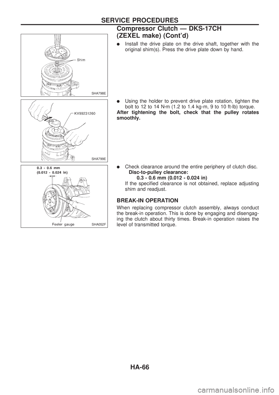
lInstall the drive plate on the drive shaft, together with the
original shim(s). Press the drive plate down by hand.
lUsing the holder to prevent drive plate rotation, tighten the
bolt to 12 to 14 Nzm (1.2 to 1.4 kg-m, 9 to 10 ft-lb) torque.
After tightening the bolt, check that the pulley rotates
smoothly.
lCheck clearance around the entire periphery of clutch disc.
Disc-to-pulley clearance:
0.3 - 0.6 mm (0.012 - 0.024 in)
If the specified clearance is not obtained, replace adjusting
shim and readjust.
BREAK-IN OPERATION
When replacing compressor clutch assembly, always conduct
the break-in operation. This is done by engaging and disengag-
ing the clutch about thirty times. Break-in operation raises the
level of transmitted torque.
SHA798E
SHA799E
SHA052F
SERVICE PROCEDURES
Compressor Clutch Ð DKS-17CH
(ZEXEL make) (Cont'd)
HA-66
Page 938 of 1659
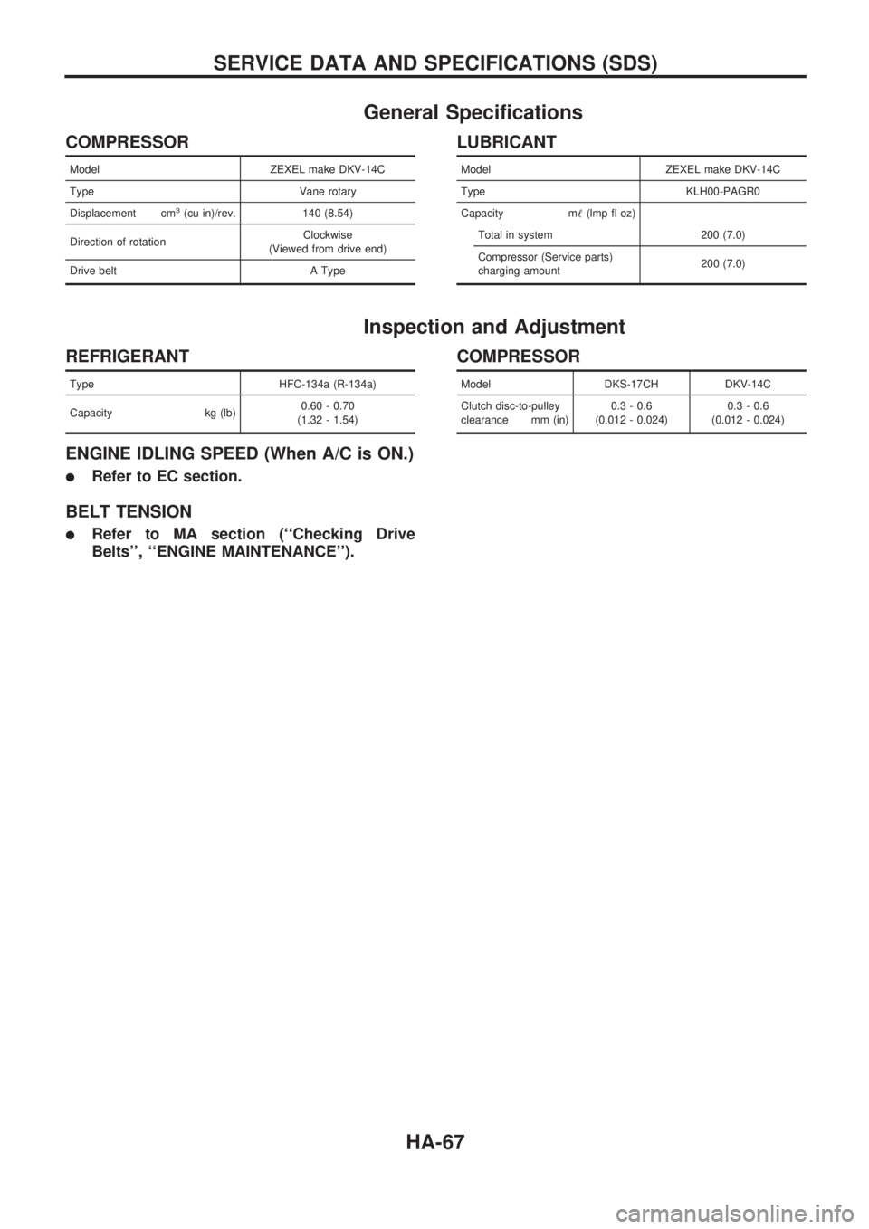
General Specifications
COMPRESSOR
Model ZEXEL make DKV-14C
Type Vane rotary
Displacement cm
3(cu in)/rev. 140 (8.54)
Direction of rotationClockwise
(Viewed from drive end)
Drive belt A Type
LUBRICANT
Model ZEXEL make DKV-14C
Type KLH00-PAGR0
Capacity m!(lmp fl oz)
Total in system 200 (7.0)
Compressor (Service parts)
charging amount200 (7.0)
Inspection and Adjustment
REFRIGERANT
Type HFC-134a (R-134a)
Capacity kg (lb)0.60 - 0.70
(1.32 - 1.54)
ENGINE IDLING SPEED (When A/C is ON.)
lRefer to EC section.
BELT TENSION
lRefer to MA section (``Checking Drive
Belts'', ``ENGINE MAINTENANCE'').
COMPRESSOR
Model DKS-17CH DKV-14C
Clutch disc-to-pulley
clearance mm (in)0.3 - 0.6
(0.012 - 0.024)0.3 - 0.6
(0.012 - 0.024)
SERVICE DATA AND SPECIFICATIONS (SDS)
HA-67
Page 939 of 1659
ENGINE LUBRICATION &
COOLING SYSTEMS
SECTION
LC
CONTENTS
PRECAUTIONS AND PREPARATION..................... 1
Liquid Gasket Application Procedure .................... 1
Special Service Tools ............................................ 2
KA
ENGINE LUBRICATION SYSTEM............................ 3
Lubrication Circuit .................................................. 3
Oil Pressure Check ................................................ 4
Oil Pump ................................................................ 4
ENGINE COOLING SYSTEM.................................... 6
Cooling Circuit........................................................ 6
System Check ........................................................ 6
Water Pump ........................................................... 7
Thermostat ............................................................. 8
Radiator.................................................................. 9
Cooling Fan (Crankshaft driven).......................... 10
TD
ENGINE LUBRICATION SYSTEM.......................... 12
Lubrication Circuit ................................................ 12
Oil Pressure Check (On-vehicle service) ............ 13
Oil Pump .............................................................. 14
Oil Filter Bracket .................................................. 16
Oil Cooler ............................................................. 17Oil Jet ................................................................... 18
ENGINE COOLING SYSTEM.................................. 19
Cooling Circuit...................................................... 19
Cooling System Inspection .................................. 20
Water Pump and Cooling Fan (Camshaft
driven) .................................................................. 21
Thermostat ........................................................... 23
Radiator................................................................ 24
Refilling Engine Coolant ...................................... 24
ENGINE ROOM FAN MOTOR ELECTRICAL
CIRCUIT................................................................... 25
Wiring Diagram .................................................... 25
Cooling Fan (Motor driven) .................................. 26
Electrical Components Inspection ....................... 26
ENGINE COOLING SYSTEM.................................. 28
Radiator (Aluminum type) .................................... 28
Overheating Cause Analysis ............................... 31
SERVICE DATA AND SPECIFICATIONS (SDS)... 32
Engine Lubrication System (KA).......................... 32
Engine Cooling System (KA) ............................... 32
Engine Lubrication System (TD).......................... 32
Engine Cooling System (TD) ............................... 32
LC
Page 940 of 1659
Liquid Gasket Application Procedure
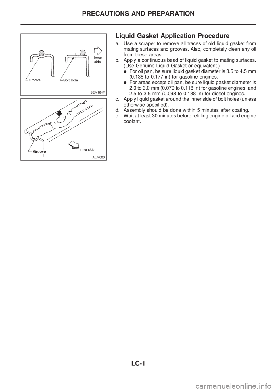
a. Use a scraper to remove all traces of old liquid gasket from
mating surfaces and grooves. Also, completely clean any oil
from these areas.
b. Apply a continuous bead of liquid gasket to mating surfaces.
(Use Genuine Liquid Gasket or equivalent.)
lFor oil pan, be sure liquid gasket diameter is 3.5 to 4.5 mm
(0.138 to 0.177 in) for gasoline engines.
lFor areas except oil pan, be sure liquid gasket diameter is
2.0 to 3.0 mm (0.079 to 0.118 in) for gasoline engines, and
2.5 to 3.5 mm (0.098 to 0.138 in) for diesel engines.
c. Apply liquid gasket around the inner side of bolt holes (unless
otherwise specified).
d. Assembly should be done within 5 minutes after coating.
e. Wait at least 30 minutes before refilling engine oil and engine
coolant.
SEM164F
AEM080
PRECAUTIONS AND PREPARATION
LC-1