NISSAN PRIMERA 1999 Electronic Repair Manual
Manufacturer: NISSAN, Model Year: 1999, Model line: PRIMERA, Model: NISSAN PRIMERA 1999Pages: 2267, PDF Size: 35.74 MB
Page 1071 of 2267
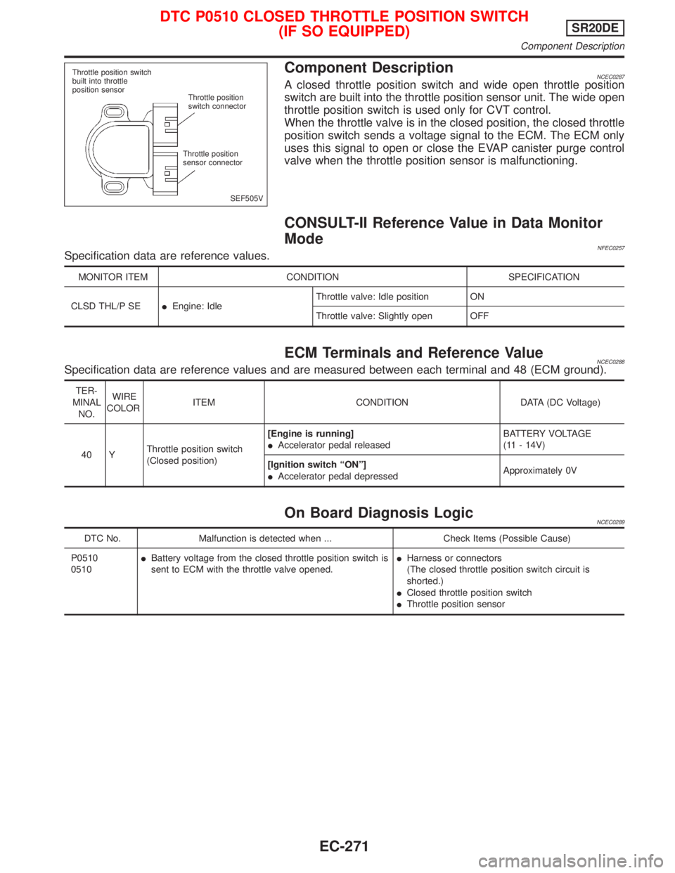
Component DescriptionNCEC0287A closed throttle position switch and wide open throttle position
switch are built into the throttle position sensor unit. The wide open
throttle position switch is used only for CVT control.
When the throttle valve is in the closed position, the closed throttle
position switch sends a voltage signal to the ECM. The ECM only
uses this signal to open or close the EVAP canister purge control
valve when the throttle position sensor is malfunctioning.
CONSULT-II Reference Value in Data Monitor
Mode
NFEC0257Specification data are reference values.
MONITOR ITEM CONDITION SPECIFICATION
CLSD THL/P SEIEngine: IdleThrottle valve: Idle position ON
Throttle valve: Slightly open OFF
ECM Terminals and Reference ValueNCEC0288Specification data are reference values and are measured between each terminal and 48 (ECM ground).
TER-
MINAL
NO.WIRE
COLORITEM CONDITION DATA (DC Voltage)
40 YThrottle position switch
(Closed position)[Engine is running]
IAccelerator pedal releasedBATTERY VOLTAGE
(11 - 14V)
[Ignition switch ªONº]
IAccelerator pedal depressedApproximately 0V
On Board Diagnosis LogicNCEC0289
DTC No. Malfunction is detected when ... Check Items (Possible Cause)
P0510
0510IBattery voltage from the closed throttle position switch is
sent to ECM with the throttle valve opened.IHarness or connectors
(The closed throttle position switch circuit is
shorted.)
IClosed throttle position switch
IThrottle position sensor
SEF505V
Throttle position switch
built into throttle
position sensor
Throttle position
switch connector
Throttle position
sensor connector
DTC P0510 CLOSED THROTTLE POSITION SWITCH
(IF SO EQUIPPED)SR20DE
Component Description
EC-271
Page 1072 of 2267
DTC Confirmation ProcedureNCEC0290CAUTION:
Always drive vehicle at a safe speed.
NOTE:
If ªDTC Confirmation Procedureº has been previously conducted,
always turn ignition switch ªOFFº and wait at least 9 seconds
before conducting the next test.
With CONSULT-II
1) Start engine and warm it up to normal operating temperature.
2) Check ignition switch ªOFFº, wait at least 9 seconds and then
start engine.
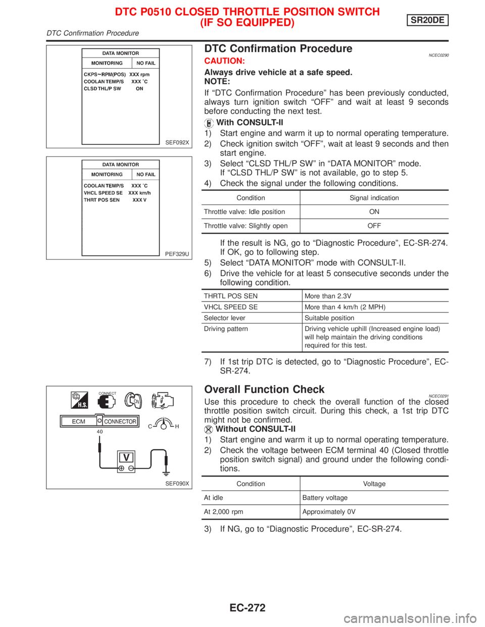
3) Select ªCLSD THL/P SWº in ªDATA MONITORº mode.
If ªCLSD THL/P SWº is not available, go to step 5.
4) Check the signal under the following conditions.
Condition Signal indication
Throttle valve: Idle position ON
Throttle valve: Slightly open OFF
If the result is NG, go to ªDiagnostic Procedureº, EC-SR-274.
If OK, go to following step.
5) Select ªDATA MONITORº mode with CONSULT-II.
6) Drive the vehicle for at least 5 consecutive seconds under the
following condition.
THRTL POS SEN More than 2.3V
VHCL SPEED SE More than 4 km/h (2 MPH)
Selector lever Suitable position
Driving pattern Driving vehicle uphill (Increased engine load)
will help maintain the driving conditions
required for this test.
7) If 1st trip DTC is detected, go to ªDiagnostic Procedureº, EC-
SR-274.
Overall Function CheckNCEC0291Use this procedure to check the overall function of the closed
throttle position switch circuit. During this check, a 1st trip DTC
might not be confirmed.
Without CONSULT-II
1) Start engine and warm it up to normal operating temperature.
2) Check the voltage between ECM terminal 40 (Closed throttle
position switch signal) and ground under the following condi-
tions.
Condition Voltage
At idle Battery voltage
At 2,000 rpm Approximately 0V
3) If NG, go to ªDiagnostic Procedureº, EC-SR-274.
SEF092X
PEF329U
SEF090X
CONNECT
DTC P0510 CLOSED THROTTLE POSITION SWITCH
(IF SO EQUIPPED)SR20DE
DTC Confirmation Procedure
EC-272
Page 1073 of 2267
Wiring DiagramNCEC0292
YEC846
BATTERY
Refer to
EL-POWER.: Detectable line for DTC
: Non-detectable line for DTC
ECM
RELAY
OFF
CLOSEDWIDE
OPEN
OFFTHROTTLE
POSITION
SWITCH
(CLOSED THROTTLE POSITION
SWITCH AND WIDE OPEN
THROTTLE POSITION SWITCH
ECM
DTC P0510 CLOSED THROTTLE POSITION SWITCH
(IF SO EQUIPPED)SR20DE
Wiring Diagram
EC-273
Page 1074 of 2267
Diagnostic ProcedureNCEC0293
1 CHECK POWER SUPPLY
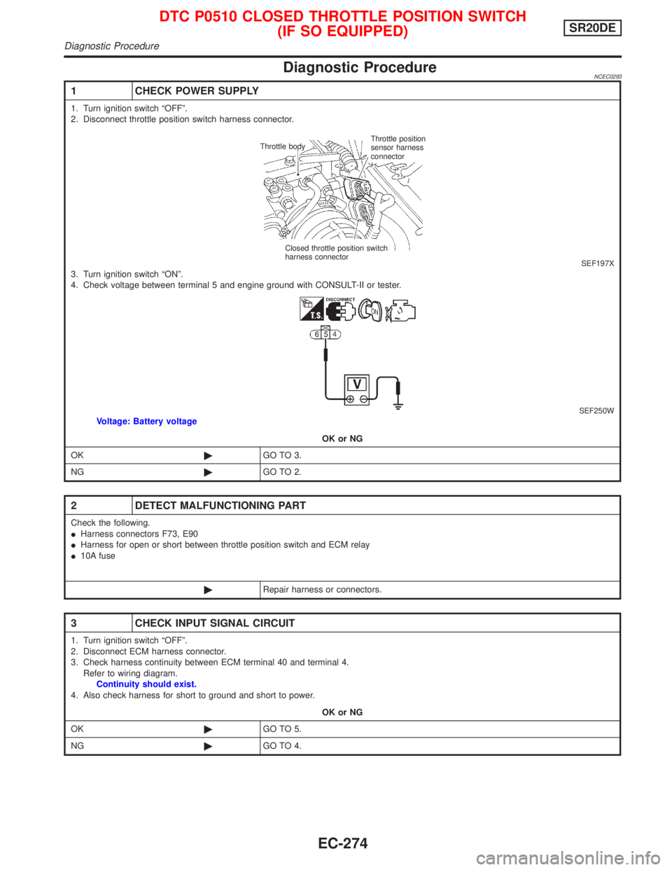
1. Turn ignition switch ªOFFº.
2. Disconnect throttle position switch harness connector.
SEF197X3. Turn ignition switch ªONº.
4. Check voltage between terminal 5 and engine ground with CONSULT-II or tester.
SEF250WVoltage: Battery voltage
OK or NG
OK©GO TO 3.
NG©GO TO 2.
2 DETECT MALFUNCTIONING PART
Check the following.
IHarness connectors F73, E90
IHarness for open or short between throttle position switch and ECM relay
I10A fuse
©Repair harness or connectors.
3 CHECK INPUT SIGNAL CIRCUIT
1. Turn ignition switch ªOFFº.
2. Disconnect ECM harness connector.
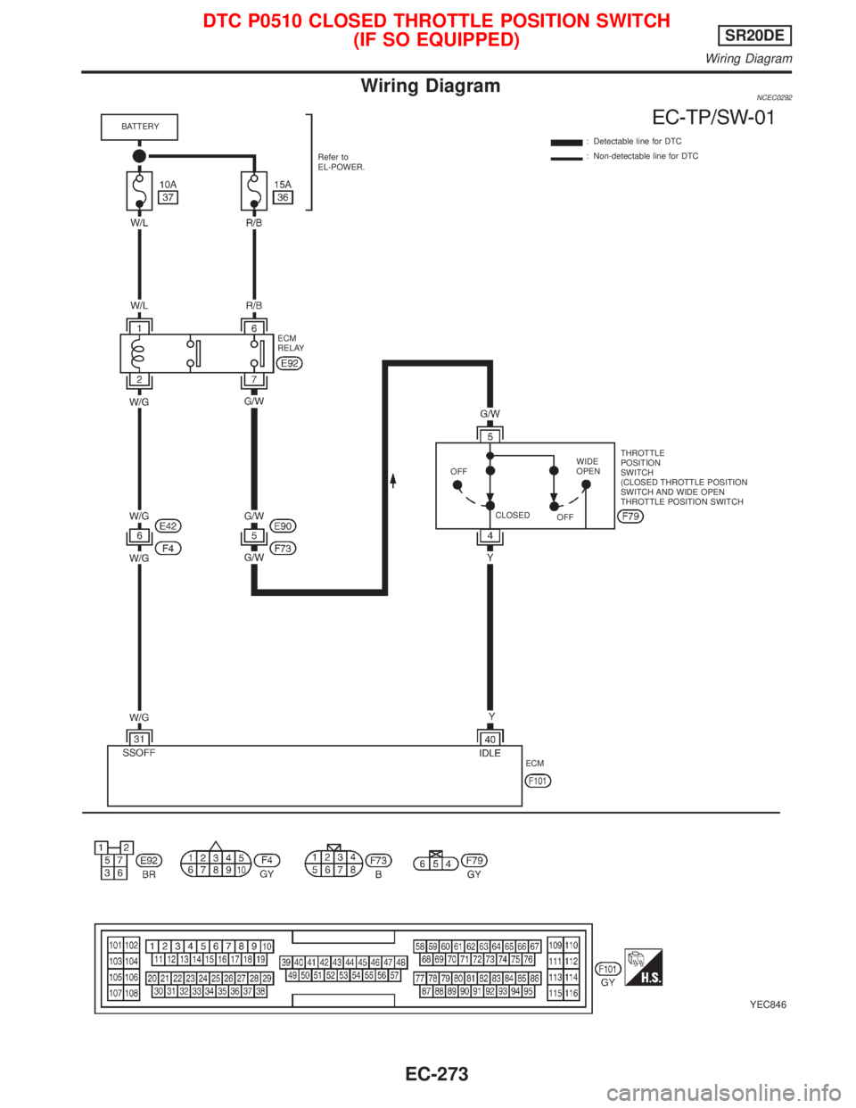
3. Check harness continuity between ECM terminal 40 and terminal 4.
Refer to wiring diagram.
Continuity should exist.
4. Also check harness for short to ground and short to power.
OK or NG
OK©GO TO 5.
NG©GO TO 4.
Throttle bodyThrottle position
sensor harness
connector
Closed throttle position switch
harness connector
DTC P0510 CLOSED THROTTLE POSITION SWITCH
(IF SO EQUIPPED)SR20DE
Diagnostic Procedure
EC-274
Page 1075 of 2267
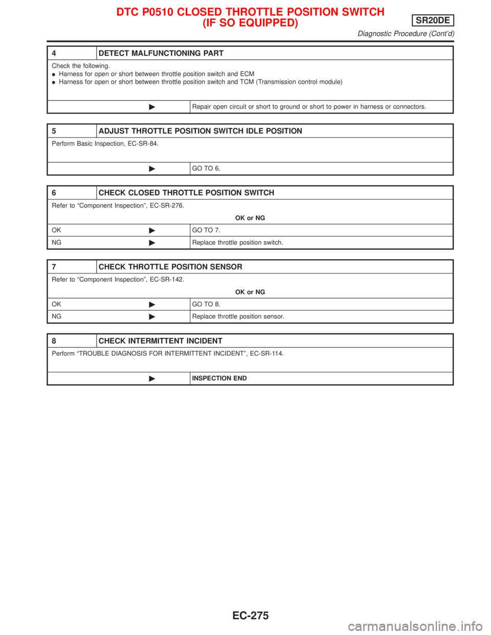
4 DETECT MALFUNCTIONING PART
Check the following.
IHarness for open or short between throttle position switch and ECM
IHarness for open or short between throttle position switch and TCM (Transmission control module)
©Repair open circuit or short to ground or short to power in harness or connectors.
5 ADJUST THROTTLE POSITION SWITCH IDLE POSITION
Perform Basic Inspection, EC-SR-84.
©GO TO 6.
6 CHECK CLOSED THROTTLE POSITION SWITCH
Refer to ªComponent Inspectionº, EC-SR-276.
OK or NG
OK©GO TO 7.
NG©Replace throttle position switch.
7 CHECK THROTTLE POSITION SENSOR
Refer to ªComponent Inspectionº, EC-SR-142.
OK or NG
OK©GO TO 8.
NG©Replace throttle position sensor.
8 CHECK INTERMITTENT INCIDENT
Perform ªTROUBLE DIAGNOSIS FOR INTERMITTENT INCIDENTº, EC-SR-114.
©INSPECTION END
DTC P0510 CLOSED THROTTLE POSITION SWITCH
(IF SO EQUIPPED)SR20DE
Diagnostic Procedure (Cont'd)
EC-275
Page 1076 of 2267
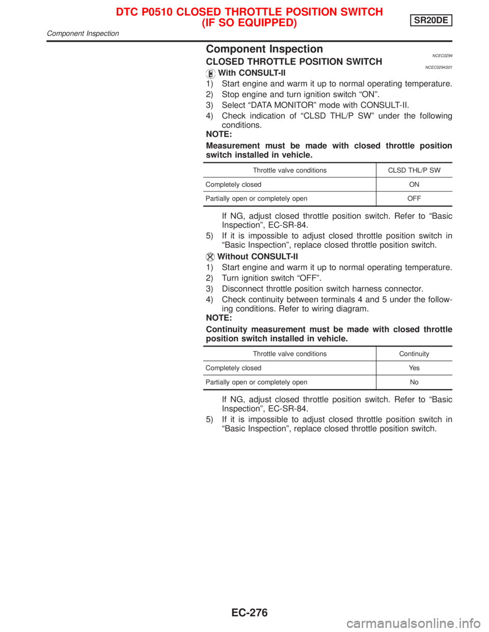
Component InspectionNCEC0294CLOSED THROTTLE POSITION SWITCHNCEC0294S01With CONSULT-II
1) Start engine and warm it up to normal operating temperature.
2) Stop engine and turn ignition switch ªONº.
3) Select ªDATA MONITORº mode with CONSULT-II.
4) Check indication of ªCLSD THL/P SWº under the following
conditions.
NOTE:
Measurement must be made with closed throttle position
switch installed in vehicle.
Throttle valve conditions CLSD THL/P SW
Completely closed ON
Partially open or completely open OFF
If NG, adjust closed throttle position switch. Refer to ªBasic
Inspectionº, EC-SR-84.
5) If it is impossible to adjust closed throttle position switch in
ªBasic Inspectionº, replace closed throttle position switch.
Without CONSULT-II
1) Start engine and warm it up to normal operating temperature.
2) Turn ignition switch ªOFFº.
3) Disconnect throttle position switch harness connector.
4) Check continuity between terminals 4 and 5 under the follow-
ing conditions. Refer to wiring diagram.
NOTE:
Continuity measurement must be made with closed throttle
position switch installed in vehicle.
Throttle valve conditions Continuity
Completely closed Yes
Partially open or completely open No
If NG, adjust closed throttle position switch. Refer to ªBasic
Inspectionº, EC-SR-84.
5) If it is impossible to adjust closed throttle position switch in
ªBasic Inspectionº, replace closed throttle position switch.
DTC P0510 CLOSED THROTTLE POSITION SWITCH
(IF SO EQUIPPED)SR20DE
Component Inspection
EC-276
Page 1077 of 2267
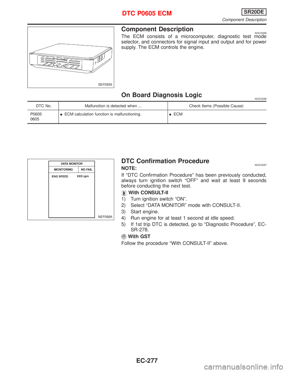
Component DescriptionNCEC0295The ECM consists of a microcomputer, diagnostic test mode
selector, and connectors for signal input and output and for power
supply. The ECM controls the engine.
On Board Diagnosis LogicNCEC0296
DTC No. Malfunction is detected when ... Check Items (Possible Cause)
P0605
0605IECM calculation function is malfunctioning.IECM
DTC Confirmation ProcedureNCEC0297NOTE:
If ªDTC Confirmation Procedureº has been previously conducted,
always turn ignition switch ªOFFº and wait at least 9 seconds
before conducting the next test.
With CONSULT-II
1) Turn ignition switch ªONº.
2) Select ªDATA MONITORº mode with CONSULT-II.
3) Start engine.
4) Run engine for at least 1 second at idle speed.
5) If 1st trip DTC is detected, go to ªDiagnostic Procedureº, EC-
SR-278.
With GST
Follow the procedure ªWith CONSULT-IIº above.
SEF093X
NEF068A
DTC P0605 ECMSR20DE
Component Description
EC-277
Page 1078 of 2267
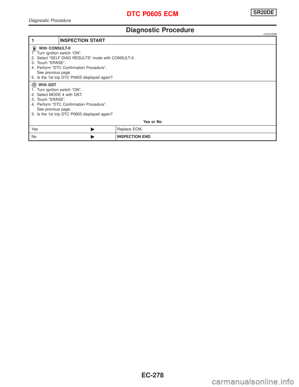
Diagnostic Procedure=NCEC0298
1 INSPECTION START
With CONSULT-II
1. Turn ignition switch ªONº.
2. Select ªSELF DIAG RESULTSº mode with CONSULT-II.
3. Touch ªERASEº.
4. Perform ªDTC Confirmation Procedureº.
See previous page.
5. Is the 1st trip DTC P0605 displayed again?
With GST
1. Turn ignition switch ªONº.
2. Select MODE 4 with GST.
3. Touch ªERASEº.
4. Perform ªDTC Confirmation Procedureº.
See previous page.
5. Is the 1st trip DTC P0605 displayed again?
YesorNo
Ye s©Replace ECM.
No©INSPECTION END
DTC P0605 ECMSR20DE
Diagnostic Procedure
EC-278
Page 1079 of 2267
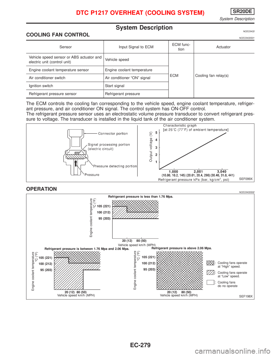
System DescriptionNCEC0433COOLING FAN CONTROLNCEC0433S01
Sensor Input Signal to ECMECM func-
tionActuator
Vehicle speed sensor or ABS actuator and
electric unit (control unit)Vehicle speed
ECM Cooling fan relay(s) Engine coolant temperature sensor Engine coolant temperature
Air conditioner switch Air conditioner ªONº signal
Ignition switch Start signal
Refrigerant pressure sensor Refrigerant pressure
The ECM controls the cooling fan corresponding to the vehicle speed, engine coolant temperature, refriger-
ant pressure, and air conditioner ON signal. The control system has ON-OFF control.
The refrigerant pressure sensor uses an electrostatic volume pressure transducer to convert refrigerant pres-
sure to voltage. The transducer is installed in the liquid tank of the air conditioner system.
OPERATIONNCEC0433S02
SEF099X
SEF198X Refrigerant pressure is less than 1.76 Mpa.
Refrigerant pressure is between 1.76 Mpa and 2.06 Mpa.Refrigerant pressure is above 2.06 Mpa. 20 (12) 80 (50)
Vehicle speed km/h (MPH)
20 (12) 80 (50)
Vehicle speed km/h (MPH)20 (12) 80 (50)
Vehicle speed km/h (MPH)Cooling fans operate
at ªHighº speed.
Cooling fans operate
at ªLowº speed.
Cooling fans
do no operate 105 (221)
100 (212)
95 (203) 105 (221)
100 (212)
95 (203)105 (221)
100 (212)
95 (203)
Engine coolant temperature
ÉC (ÉF)
Engine coolant temperature
ÉC (ÉF)
Engine coolant temperature
ÉC (ÉF)
DTC P1217 OVERHEAT (COOLING SYSTEM)SR20DE
System Description
EC-279
Page 1080 of 2267
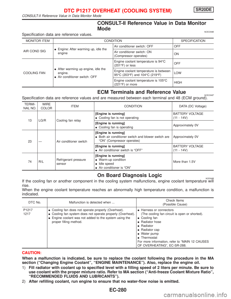
CONSULT-II Reference Value in Data Monitor
Mode
NCEC0486Specification data are reference values.
MONITOR ITEM CONDITION SPECIFICATION
AIR COND SIGIEngine: After warming up, idle the
engineAir conditioner switch: OFF OFF
Air conditioner switch: ON
(Compressor operates)ON
COOLING FANIAfter warming up engine, idle the
engine.
IAir conditioner switch: OFFEngine coolant temperature is 94ÉC
(201ÉF) or lessOFF
Engine coolant temperature is between
95ÉC (203ÉF) and 104ÉC (219ÉF)LOW
Engine coolant temperature is 105ÉC
(221ÉF) or moreHIGH
ECM Terminals and Reference ValueNCEC0487Specification data are reference values and are measured between each terminal and 48 (ECM ground).
TERMI-
NAL NO.WIRE
COLORITEM CONDITION DATA (DC Voltage)
13 LG/R Cooling fan relay[Engine is running]
ICooling fan is not operatingBATTERY VOLTAGE
(11 - 14V)
[Engine is running]
ICooling fan is operatingApproximately 0V
23 Ð Air conditioner switch[Engine is running]
IBoth air conditioner switch and blower switch are
ªONº (Compressor operates)Approximately 0V
[Engine is running]
IAir conditioner switch is ªOFFºBATTERY VOLTAGE
(11 - 14V)
74 R/LRefrigerant pressure
sensor[Engine is running]
IWarm-up condition
IIdle speed
IAir conditioner is ªONºMore than 1.5V
On Board Diagnosis LogicNCE0488If the cooling fan or another component in the cooling system malfunctions, engine coolant temperature will
rise.
When the engine coolant temperature reaches an abnormally high temperature condition, a malfunction is
indicated.
DTC No. Malfunction is detected when ...Check Items
(Possible Cause)
P1217
1217ICooling fan does not operate properly (Overheat).
ICooling fan system does not operate properly (Overheat).
IEngine coolant was not added to the system using the
proper filling method.IHarness or connectors
(The cooling fan circuit is open or shorted).
ICooling fan
IRadiator hose
IRadiator
IRadiator cap
IWater pump
IThermostat
For more information, refer to ªMAIN 12 CAUSES
OF OVERHEATINGº, EC-SR-288.
CAUTION:
When a malfunction is indicated, be sure to replace the coolant following the procedure in the MA
section (ªChanging Engine Coolantº, ªENGINE MAINTENANCEº). Also, replace the engine oil.
1)Fill radiator with coolant up to specified level with a filling speed of 2 liters per minute. Be sure to
use coolant with the proper mixture ratio. Refer to MA section (ªAnti-freeze Coolant Mixture Ratioº,
ªRECOMMENDED FLUIDS AND LUBRICANTSº).
2)After refilling coolant, run engine to ensure that no water-flow noise is emitted.
DTC P1217 OVERHEAT (COOLING SYSTEM)SR20DE
CONSULT-II Reference Value in Data Monitor Mode
EC-280