NISSAN PRIMERA 1999 Electronic Repair Manual
Manufacturer: NISSAN, Model Year: 1999, Model line: PRIMERA, Model: NISSAN PRIMERA 1999Pages: 2267, PDF Size: 35.74 MB
Page 1091 of 2267

DTC Confirmation ProcedureNCEC0330NOTE:
If ªDTC Confirmation Procedureº has been previously conducted,
always turn ignition switch ªOFFº and wait at least 5 seconds
before conducting the next test.
With CONSULT-II
1) Turn ignition switch ªONº and select ªDATA MONITORº mode
with CONSULT-II.
2) Start engine and run it for at least 4 minutes at idle speed.
3) If 1st trip DTC is detected, go to ªDiagnostic Procedureº, EC-
SR-293.
With GST
Follow the procedure ªWith CONSULT-IIº above.
NEF068A
DTC P1336 CRANKSHAFT POSITION SENSOR
(CKPS) (OBD) (COG)SR20DE
DTC Confirmation Procedure
EC-291
Page 1092 of 2267
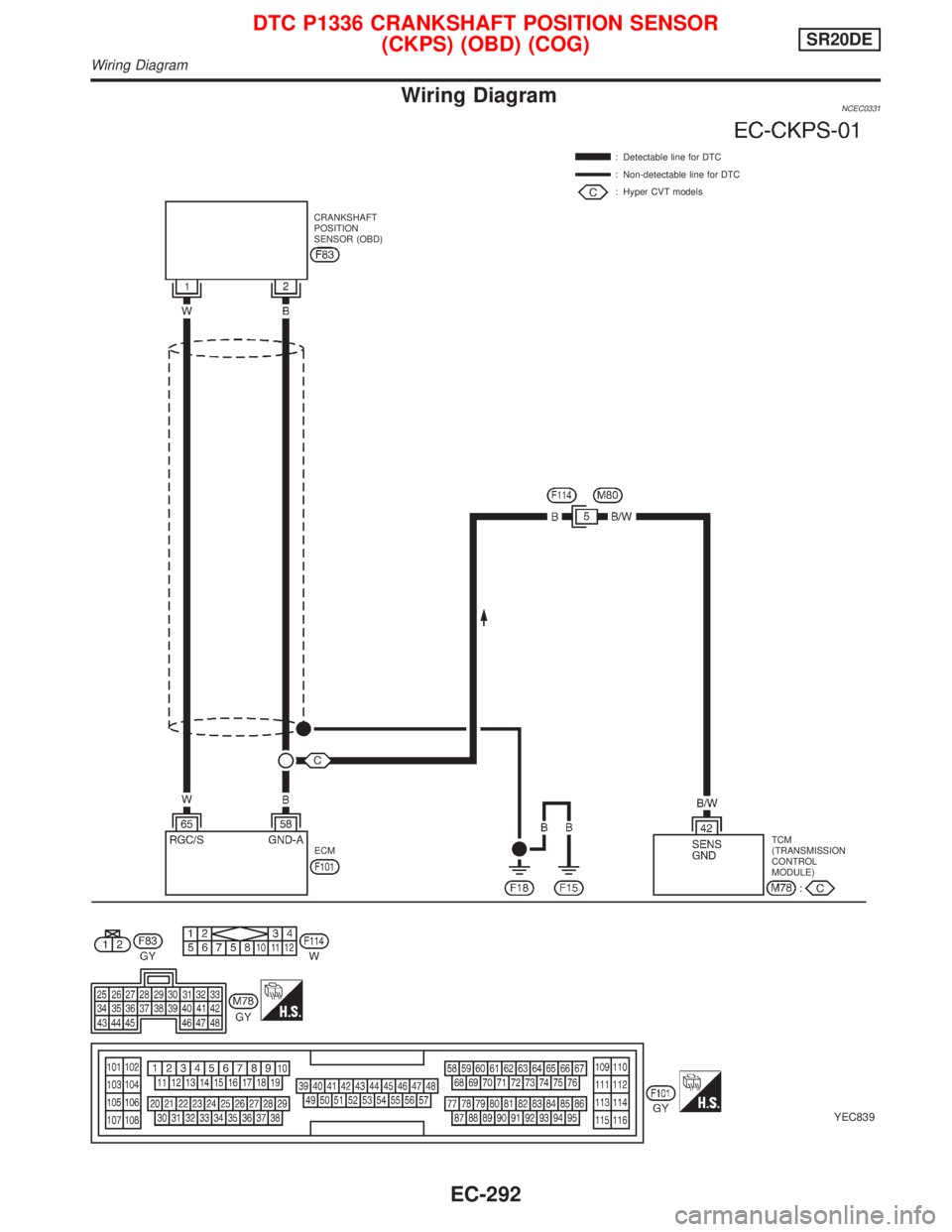
Wiring DiagramNCEC0331
YEC839
: Detectable line for DTC
: Non-detectable line for DTC
: Hyper CVT models
ECMTCM
(TRANSMISSION
CONTROL
MODULE) CRANKSHAFT
POSITION
SENSOR (OBD)
DTC P1336 CRANKSHAFT POSITION SENSOR
(CKPS) (OBD) (COG)SR20DE
Wiring Diagram
EC-292
Page 1093 of 2267
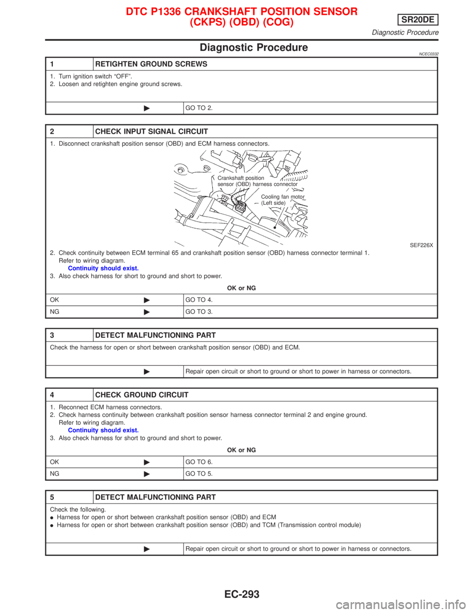
Diagnostic ProcedureNCEC0332
1 RETIGHTEN GROUND SCREWS
1. Turn ignition switch ªOFFº.
2. Loosen and retighten engine ground screws.
©GO TO 2.
2 CHECK INPUT SIGNAL CIRCUIT
1. Disconnect crankshaft position sensor (OBD) and ECM harness connectors.
SEF226X2. Check continuity between ECM terminal 65 and crankshaft position sensor (OBD) harness connector terminal 1.
Refer to wiring diagram.
Continuity should exist.
3. Also check harness for short to ground and short to power.
OK or NG
OK©GO TO 4.
NG©GO TO 3.
3 DETECT MALFUNCTIONING PART
Check the harness for open or short between crankshaft position sensor (OBD) and ECM.
©Repair open circuit or short to ground or short to power in harness or connectors.
4 CHECK GROUND CIRCUIT
1. Reconnect ECM harness connectors.
2. Check harness continuity between crankshaft position sensor harness connector terminal 2 and engine ground.
Refer to wiring diagram.
Continuity should exist.
3. Also check harness for short to ground and short to power.
OK or NG
OK©GO TO 6.
NG©GO TO 5.
5 DETECT MALFUNCTIONING PART
Check the following.
IHarness for open or short between crankshaft position sensor (OBD) and ECM
IHarness for open or short between crankshaft position sensor (OBD) and TCM (Transmission control module)
©Repair open circuit or short to ground or short to power in harness or connectors.
Crankshaft position
sensor (OBD) harness connector
Cooling fan motor
(Left side)
DTC P1336 CRANKSHAFT POSITION SENSOR
(CKPS) (OBD) (COG)SR20DE
Diagnostic Procedure
EC-293
Page 1094 of 2267
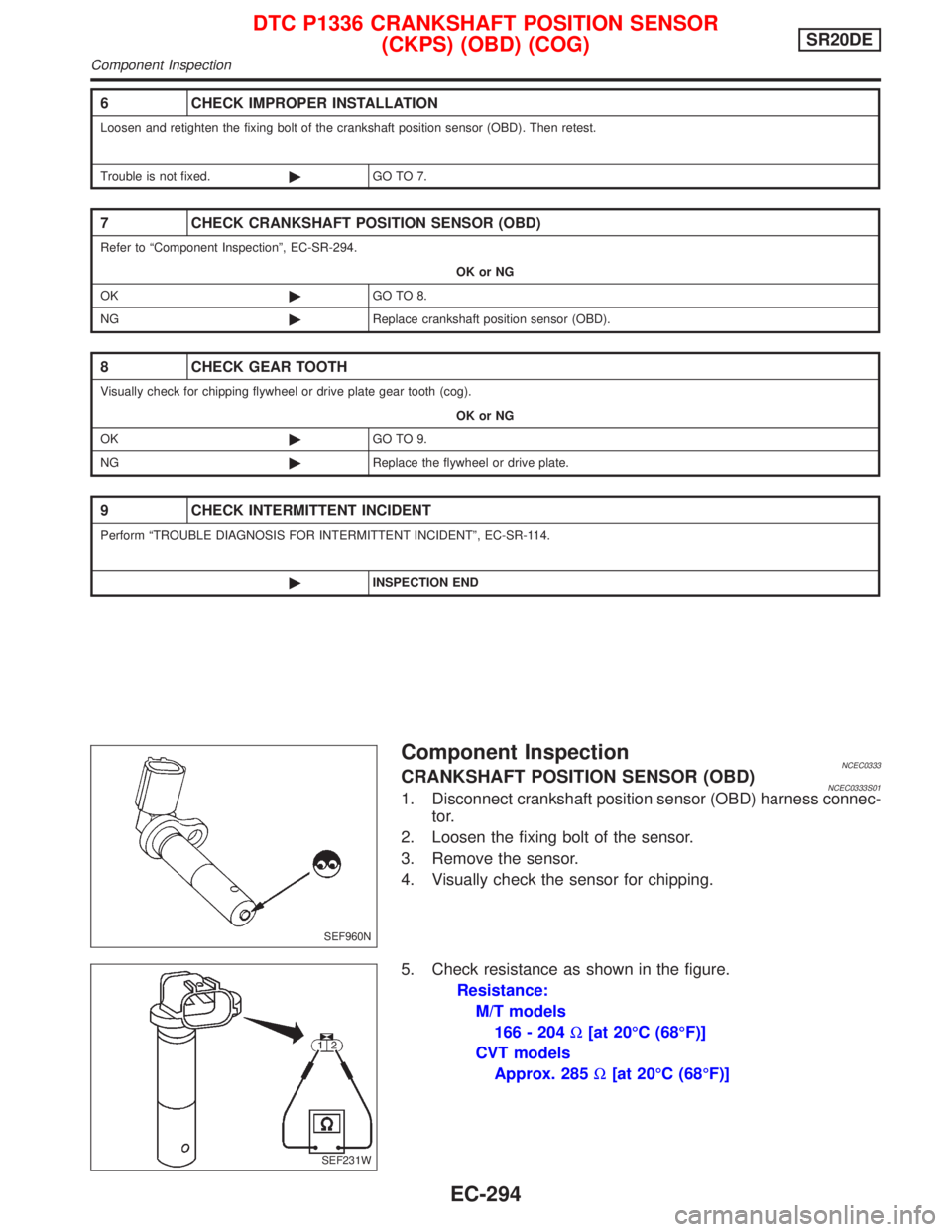
Component InspectionNCEC0333CRANKSHAFT POSITION SENSOR (OBD)NCEC0333S011. Disconnect crankshaft position sensor (OBD) harness connec-
tor.
2. Loosen the fixing bolt of the sensor.
3. Remove the sensor.
4. Visually check the sensor for chipping.
5. Check resistance as shown in the figure.
Resistance:
M/T models
166 - 204W[at 20ÉC (68ÉF)]
CVT models
Approx. 285W[at 20ÉC (68ÉF)]
6 CHECK IMPROPER INSTALLATION
Loosen and retighten the fixing bolt of the crankshaft position sensor (OBD). Then retest.
Trouble is not fixed.©GO TO 7.
7 CHECK CRANKSHAFT POSITION SENSOR (OBD)
Refer to ªComponent Inspectionº, EC-SR-294.
OK or NG
OK©GO TO 8.
NG©Replace crankshaft position sensor (OBD).
8 CHECK GEAR TOOTH
Visually check for chipping flywheel or drive plate gear tooth (cog).
OK or NG
OK©GO TO 9.
NG©Replace the flywheel or drive plate.
9 CHECK INTERMITTENT INCIDENT
Perform ªTROUBLE DIAGNOSIS FOR INTERMITTENT INCIDENTº, EC-SR-114.
©INSPECTION END
SEF960N
SEF231W
DTC P1336 CRANKSHAFT POSITION SENSOR
(CKPS) (OBD) (COG)SR20DE
Component Inspection
EC-294
Page 1095 of 2267
System DescriptionNCEC0560The malfunction information related to CVT is transferred through the line (circuit) from TCM (Transmission
Control Module) to ECM. Therefore, be sure to erase the malfunction information such as DTC not only in TCM
(Transmission Control Module) but also ECM after the CVT related repair.
ECM Terminals and Reference ValueNCEC0561Specification data are reference values and are measured between each terminal and 48 (ECM ground).
TER-
MINAL
NO.WIRE
COLORITEM CONDITION DATA (DC Voltage)
91 PU/Y CVT check signal[Ignition switch ªONº]
[Engine is running]0 - Approximately 5V
On Board Diagnosis LogicNCEC0562
DTC No. Malfunction is detected when ... Check Items (Possible Cause)
P1605
1605IAn incorrect signal from TCM (Transmission Control
Module) is sent to ECM.IHarness or connectors
[The communication line circuit between ECM and
TCM (Transmission Control Module) is open or
shorted.]
IDead (Weak) battery
ITCM (Transmission Control Module)
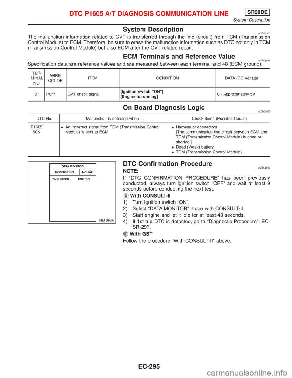
DTC Confirmation ProcedureNCEC0563NOTE:
If ªDTC CONFIRMATION PROCEDUREº has been previously
conducted, always turn ignition switch ªOFFº and wait at least 9
seconds before conducting the next test.
With CONSULT-II
1) Turn ignition switch ªONº.
2) Select ªDATA MONITORº mode with CONSULT-II.
3) Start engine and let it idle for at least 40 seconds.
4) If 1st trip DTC is detected, go to ªDiagnostic Procedureº, EC-
SR-297.
With GST
Follow the procedure ªWith CONSULT-IIº above.
NEF068A
DTC P1605 A/T DIAGNOSIS COMMUNICATION LINESR20DE
System Description
EC-295
Page 1096 of 2267
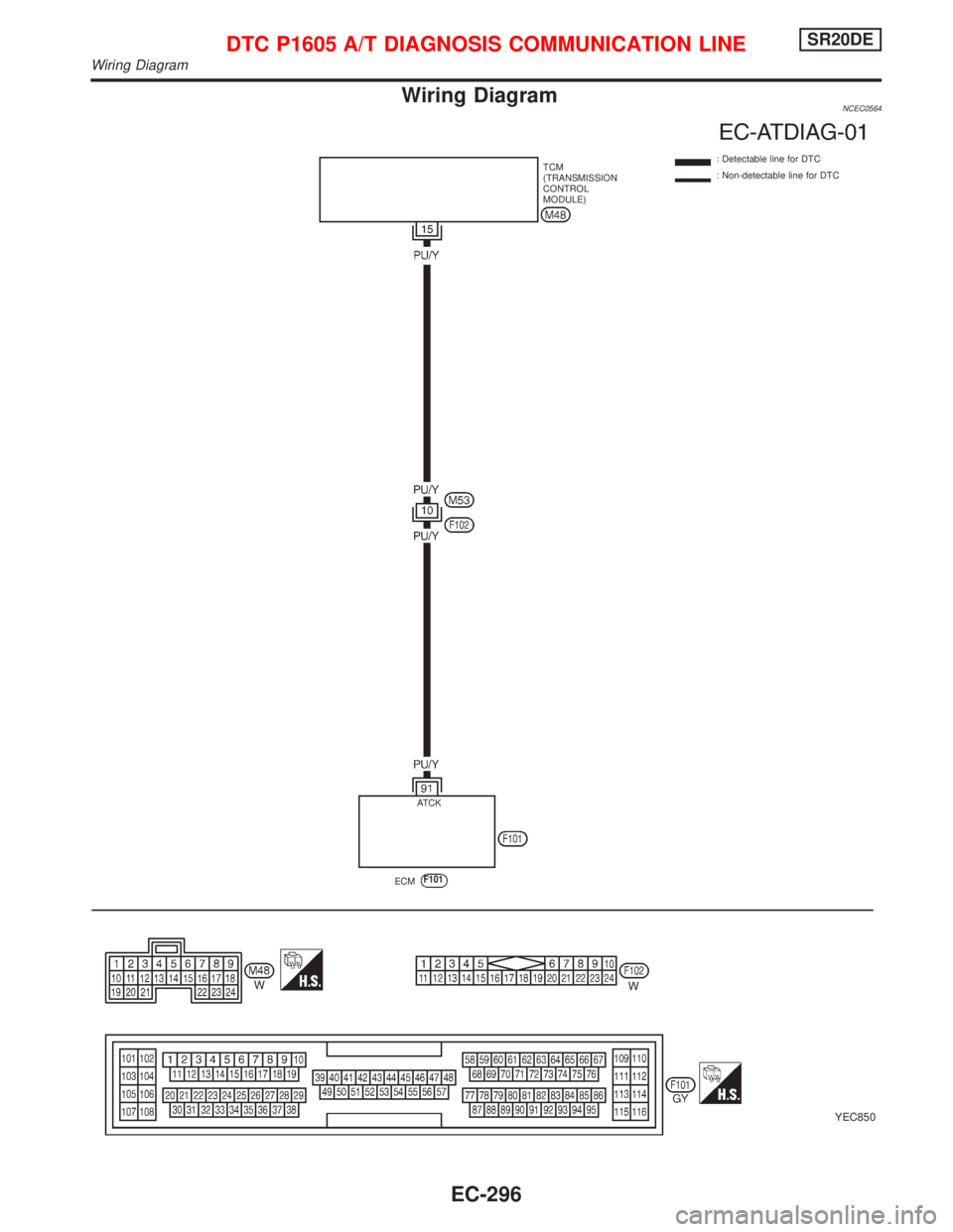
Wiring DiagramNCEC0564
YEC850
: Detectable line for DTC
: Non-detectable line for DTC TCM
(TRANSMISSION
CONTROL
MODULE)
ECM
F101
.ATCK
DTC P1605 A/T DIAGNOSIS COMMUNICATION LINESR20DE
Wiring Diagram
EC-296
Page 1097 of 2267
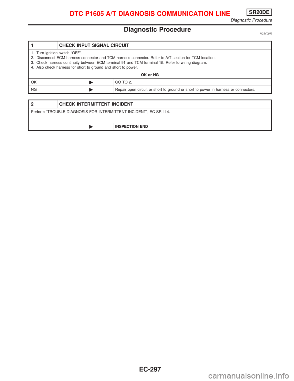
Diagnostic ProcedureNCEC0565
1 CHECK INPUT SIGNAL CIRCUIT
1. Turn ignition switch ªOFFº.
2. Disconnect ECM harness connector and TCM harness connector. Refer to A/T section for TCM location.
3. Check harness continuity between ECM terminal 91 and TCM terminal 15. Refer to wiring diagram.
4. Also check harness for short to ground and short to power.
OK or NG
OK©GO TO 2.
NG©Repair open circuit or short to ground or short to power in harness or connectors.
2 CHECK INTERMITTENT INCIDENT
Perform ªTROUBLE DIAGNOSIS FOR INTERMITTENT INCIDENTº, EC-SR-114.
©INSPECTION END
DTC P1605 A/T DIAGNOSIS COMMUNICATION LINESR20DE
Diagnostic Procedure
EC-297
Page 1098 of 2267
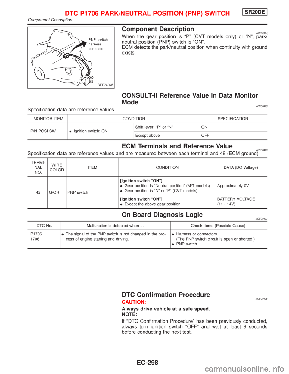
Component DescriptionNCEC0424When the gear position is ªPº (CVT models only) or ªNº, park/
neutral position (PNP) switch is ªONº.
ECM detects the park/neutral position when continuity with ground
exists.
CONSULT-II Reference Value in Data Monitor
Mode
NCEC0425Specification data are reference values.
MONITOR ITEM CONDITION SPECIFICATION
P/N POSI SWIIgnition switch: ONShift lever: ªPº or ªNº ON
Except above OFF
ECM Terminals and Reference ValueNCEC0426Specification data are reference values and are measured between each terminal and 48 (ECM ground).
TERMI-
NAL
NO.WIRE
COLORITEM CONDITION DATA (DC Voltage)
42 G/OR PNP switch[Ignition switch ªONº]
IGear position is ªNeutral positionº (M/T models)
IGear position is ªNº or ªPº (CVT models)Approximately 0V
[Ignition switch ªONº]
IExcept the above gear positionBATTERY VOLTAGE
(11 - 14V)
On Board Diagnosis LogicNCEC0427
DTC No. Malfunction is detected when ... Check Items (Possible Cause)
P1706
1706IThe signal of the PNP switch is not changed in the pro-
cess of engine starting and driving.IHarness or connectors
(The PNP switch circuit is open or shorted.)
IPNP switch
DTC Confirmation ProcedureNCEC0428CAUTION:
Always drive vehicle at a safe speed.
NOTE:
If ªDTC Confirmation Procedureº has been previously conducted,
always turn ignition switch ªOFFº and wait at least 9 seconds
before conducting the next test.
SEF740W
DTC P1706 PARK/NEUTRAL POSITION (PNP) SWITCHSR20DE
Component Description
EC-298
Page 1099 of 2267
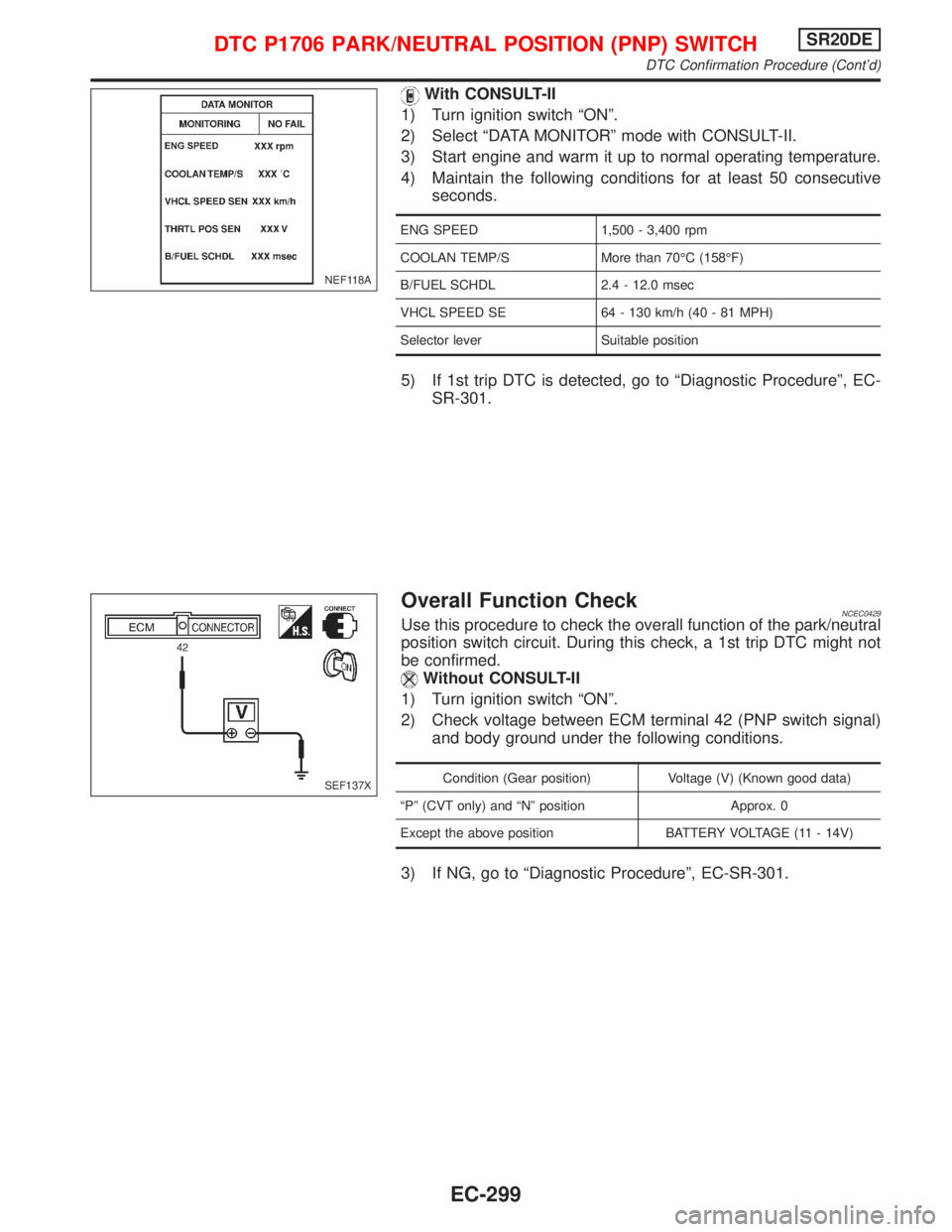
With CONSULT-II
1) Turn ignition switch ªONº.
2) Select ªDATA MONITORº mode with CONSULT-II.
3) Start engine and warm it up to normal operating temperature.
4) Maintain the following conditions for at least 50 consecutive
seconds.
ENG SPEED 1,500 - 3,400 rpm
COOLAN TEMP/S More than 70ÉC (158ÉF)
B/FUEL SCHDL 2.4 - 12.0 msec
VHCL SPEED SE 64 - 130 km/h (40 - 81 MPH)
Selector lever Suitable position
5) If 1st trip DTC is detected, go to ªDiagnostic Procedureº, EC-
SR-301.
Overall Function CheckNCEC0429Use this procedure to check the overall function of the park/neutral
position switch circuit. During this check, a 1st trip DTC might not
be confirmed.
Without CONSULT-II
1) Turn ignition switch ªONº.
2) Check voltage between ECM terminal 42 (PNP switch signal)
and body ground under the following conditions.
Condition (Gear position) Voltage (V) (Known good data)
ªPº (CVT only) and ªNº position Approx. 0
Except the above position BATTERY VOLTAGE (11 - 14V)
3) If NG, go to ªDiagnostic Procedureº, EC-SR-301.
NEF118A
SEF137X
DTC P1706 PARK/NEUTRAL POSITION (PNP) SWITCHSR20DE
DTC Confirmation Procedure (Cont'd)
EC-299
Page 1100 of 2267
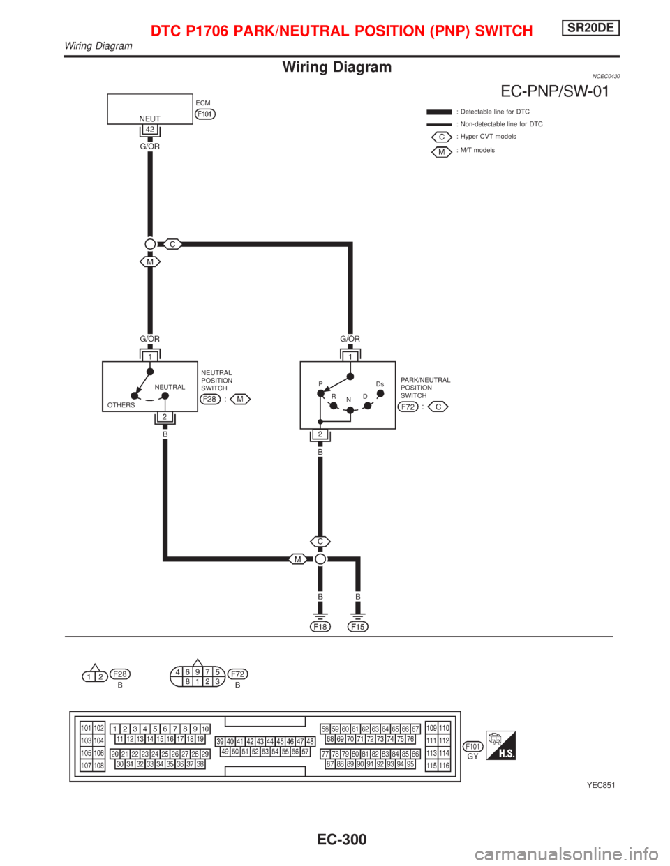
Wiring DiagramNCEC0430
YEC851
: Detectable line for DTC
: Non-detectable line for DTC
: Hyper CVT models
: M/T models ECM
PARK/NEUTRAL
POSITION
SWITCH NEUTRAL
POSITION
SWITCH NEUTRAL
OTHERSP
R
NDDs
DTC P1706 PARK/NEUTRAL POSITION (PNP) SWITCHSR20DE
Wiring Diagram
EC-300