NISSAN PRIMERA 1999 Electronic Repair Manual
Manufacturer: NISSAN, Model Year: 1999, Model line: PRIMERA, Model: NISSAN PRIMERA 1999Pages: 2267, PDF Size: 35.74 MB
Page 1031 of 2267

Wiring DiagramNCEC0210
YEC089A
DTC P0325 KNOCK SENSOR (KS)SR20DE
Wiring Diagram
EC-231
Page 1032 of 2267
Diagnostic ProcedureNCEC0211
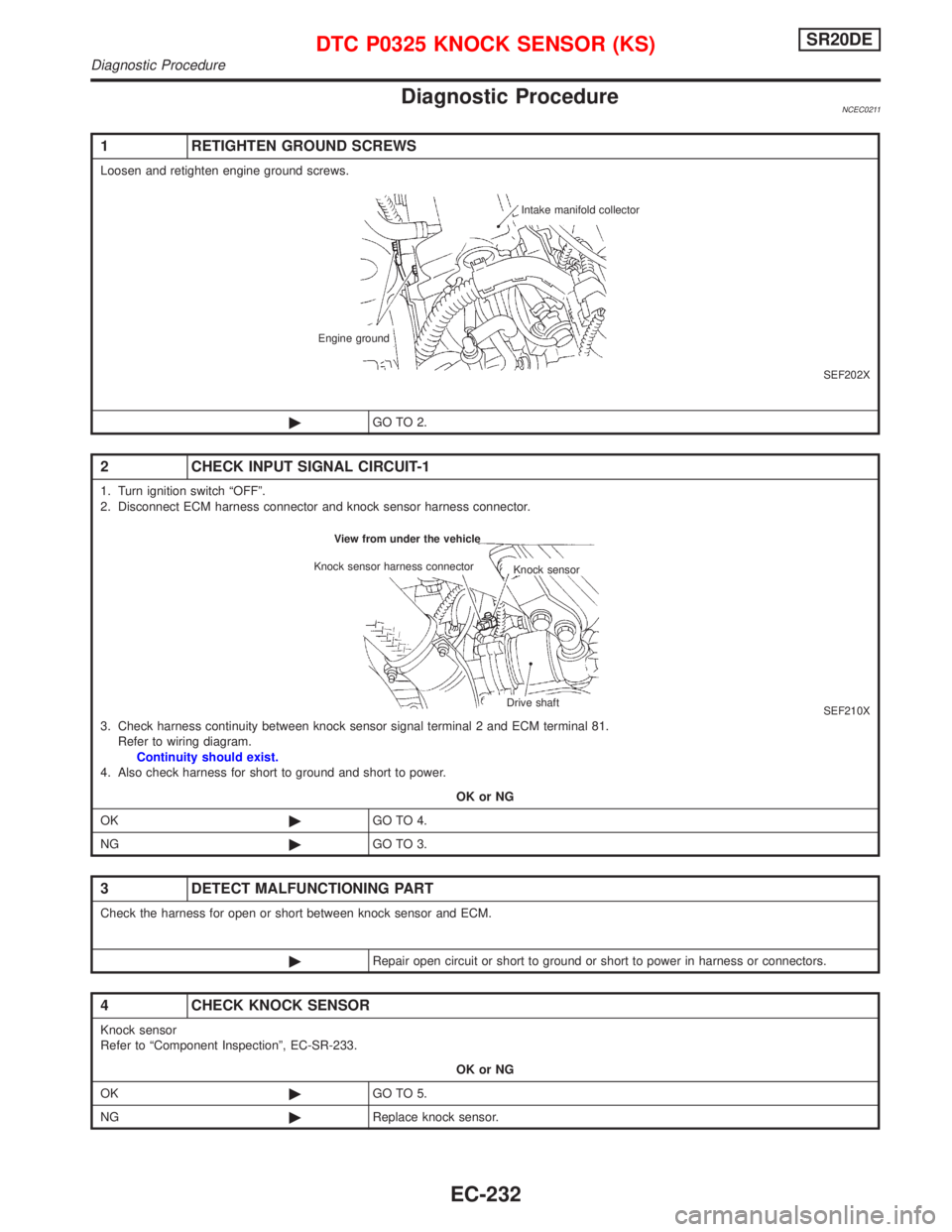
1 RETIGHTEN GROUND SCREWS
Loosen and retighten engine ground screws.
SEF202X
©GO TO 2.
2 CHECK INPUT SIGNAL CIRCUIT-1
1. Turn ignition switch ªOFFº.
2. Disconnect ECM harness connector and knock sensor harness connector.
SEF210X3. Check harness continuity between knock sensor signal terminal 2 and ECM terminal 81.
Refer to wiring diagram.
Continuity should exist.
4. Also check harness for short to ground and short to power.
OK or NG
OK©GO TO 4.
NG©GO TO 3.
3 DETECT MALFUNCTIONING PART
Check the harness for open or short between knock sensor and ECM.
©Repair open circuit or short to ground or short to power in harness or connectors.
4 CHECK KNOCK SENSOR
Knock sensor
Refer to ªComponent Inspectionº, EC-SR-233.
OK or NG
OK©GO TO 5.
NG©Replace knock sensor.
Intake manifold collector
Engine ground
Knock sensor Knock sensor harness connector
Drive shaft View from under the vehicle
DTC P0325 KNOCK SENSOR (KS)SR20DE
Diagnostic Procedure
EC-232
Page 1033 of 2267
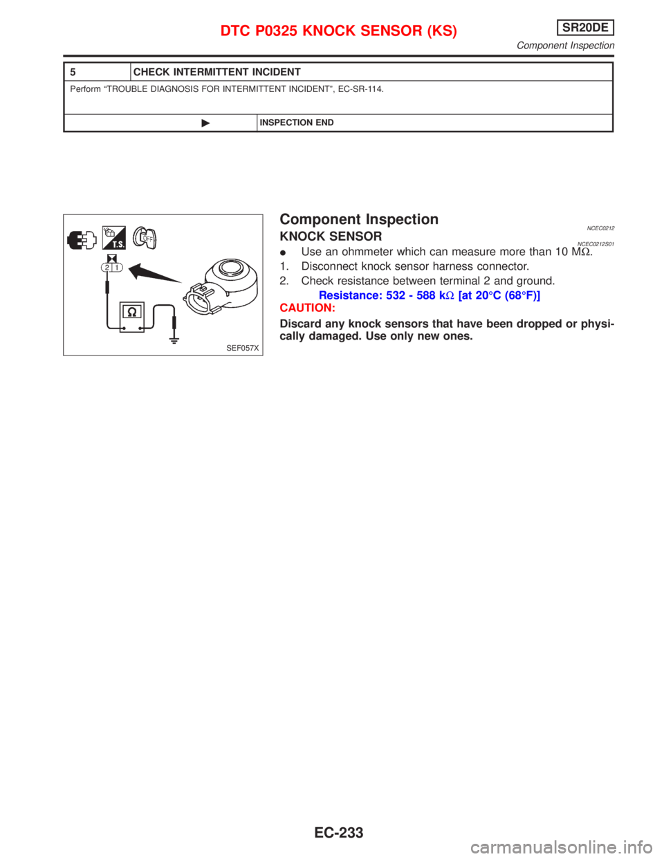
Component InspectionNCEC0212KNOCK SENSORNCEC0212S01IUse an ohmmeter which can measure more than 10 MW.
1. Disconnect knock sensor harness connector.
2. Check resistance between terminal 2 and ground.
Resistance: 532 - 588 kW[at 20ÉC (68ÉF)]
CAUTION:
Discard any knock sensors that have been dropped or physi-
cally damaged. Use only new ones.
5 CHECK INTERMITTENT INCIDENT
Perform ªTROUBLE DIAGNOSIS FOR INTERMITTENT INCIDENTº, EC-SR-114.
©INSPECTION END
SEF057X
DTC P0325 KNOCK SENSOR (KS)SR20DE
Component Inspection
EC-233
Page 1034 of 2267
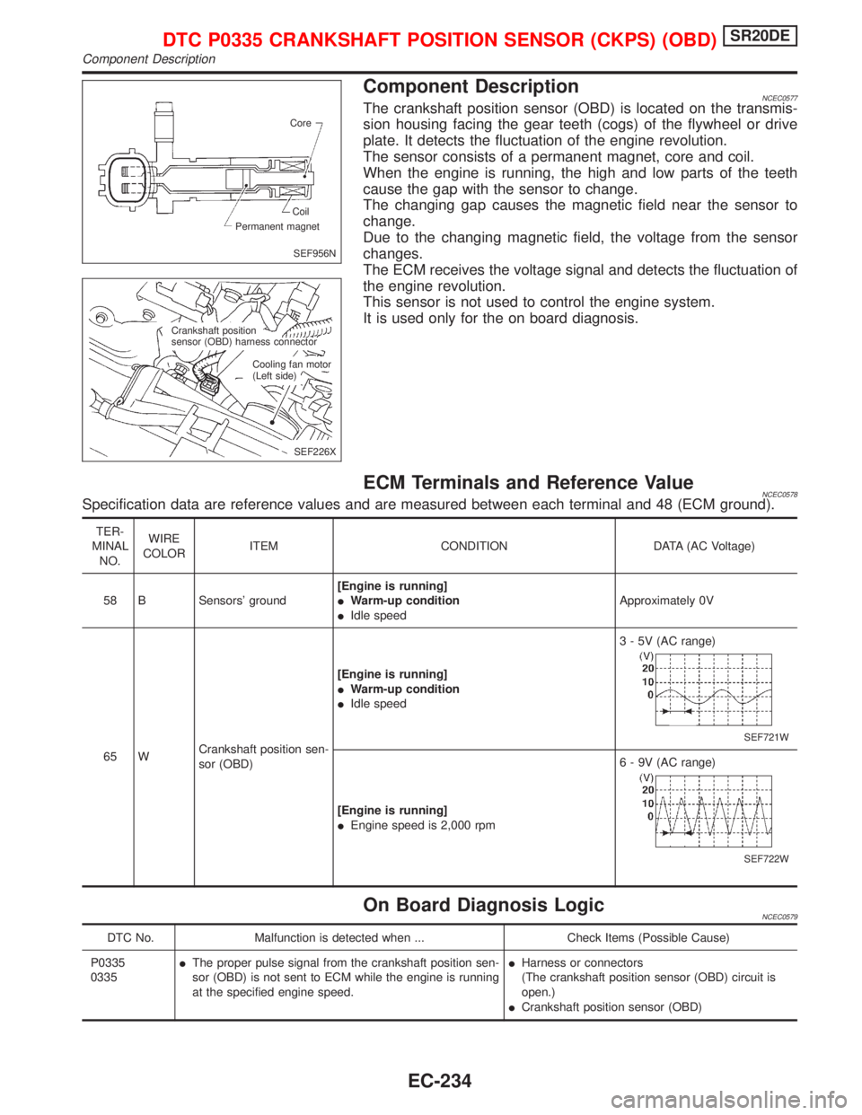
Component DescriptionNCEC0577The crankshaft position sensor (OBD) is located on the transmis-
sion housing facing the gear teeth (cogs) of the flywheel or drive
plate. It detects the fluctuation of the engine revolution.
The sensor consists of a permanent magnet, core and coil.
When the engine is running, the high and low parts of the teeth
cause the gap with the sensor to change.
The changing gap causes the magnetic field near the sensor to
change.
Due to the changing magnetic field, the voltage from the sensor
changes.
The ECM receives the voltage signal and detects the fluctuation of
the engine revolution.
This sensor is not used to control the engine system.
It is used only for the on board diagnosis.
ECM Terminals and Reference ValueNCEC0578Specification data are reference values and are measured between each terminal and 48 (ECM ground).
TER-
MINAL
NO.WIRE
COLORITEM CONDITION DATA (AC Voltage)
58 B Sensors' ground[Engine is running]
IWarm-up condition
IIdle speedApproximately 0V
65 WCrankshaft position sen-
sor (OBD)[Engine is running]
IWarm-up condition
IIdle speed3 - 5V (AC range)
SEF721W
[Engine is running]
IEngine speed is 2,000 rpm6 - 9V (AC range)
SEF722W
On Board Diagnosis LogicNCEC0579
DTC No. Malfunction is detected when ... Check Items (Possible Cause)
P0335
0335IThe proper pulse signal from the crankshaft position sen-
sor (OBD) is not sent to ECM while the engine is running
at the specified engine speed.IHarness or connectors
(The crankshaft position sensor (OBD) circuit is
open.)
ICrankshaft position sensor (OBD)
SEF956N Core
Permanent magnetCoil
SEF226X Crankshaft position
sensor (OBD) harness connector
Cooling fan motor
(Left side)
DTC P0335 CRANKSHAFT POSITION SENSOR (CKPS) (OBD)SR20DE
Component Description
EC-234
Page 1035 of 2267
DTC Confirmation ProcedureNCEC0580NOTE:
If ªDTC Confirmation Procedureº has been previously conducted,
always turn ignition switch ªOFFº and wait at least 9 seconds
before conducting the next test.
With CONSULT-II
1) Turn ignition switch ªONº and select ªDATA MONITORº mode
with CONSULT-II.
2) Start engine and run it for at least 10 seconds at idle speed.
3) If 1st trip DTC is detected, go to ªDiagnostic Procedureº, EC-
SR-237.
With GST
Follow the procedure ªWith CONSULT-IIº above.
DTC P0335 CRANKSHAFT POSITION SENSOR (CKPS) (OBD)SR20DE
DTC Confirmation Procedure
EC-235
Page 1036 of 2267
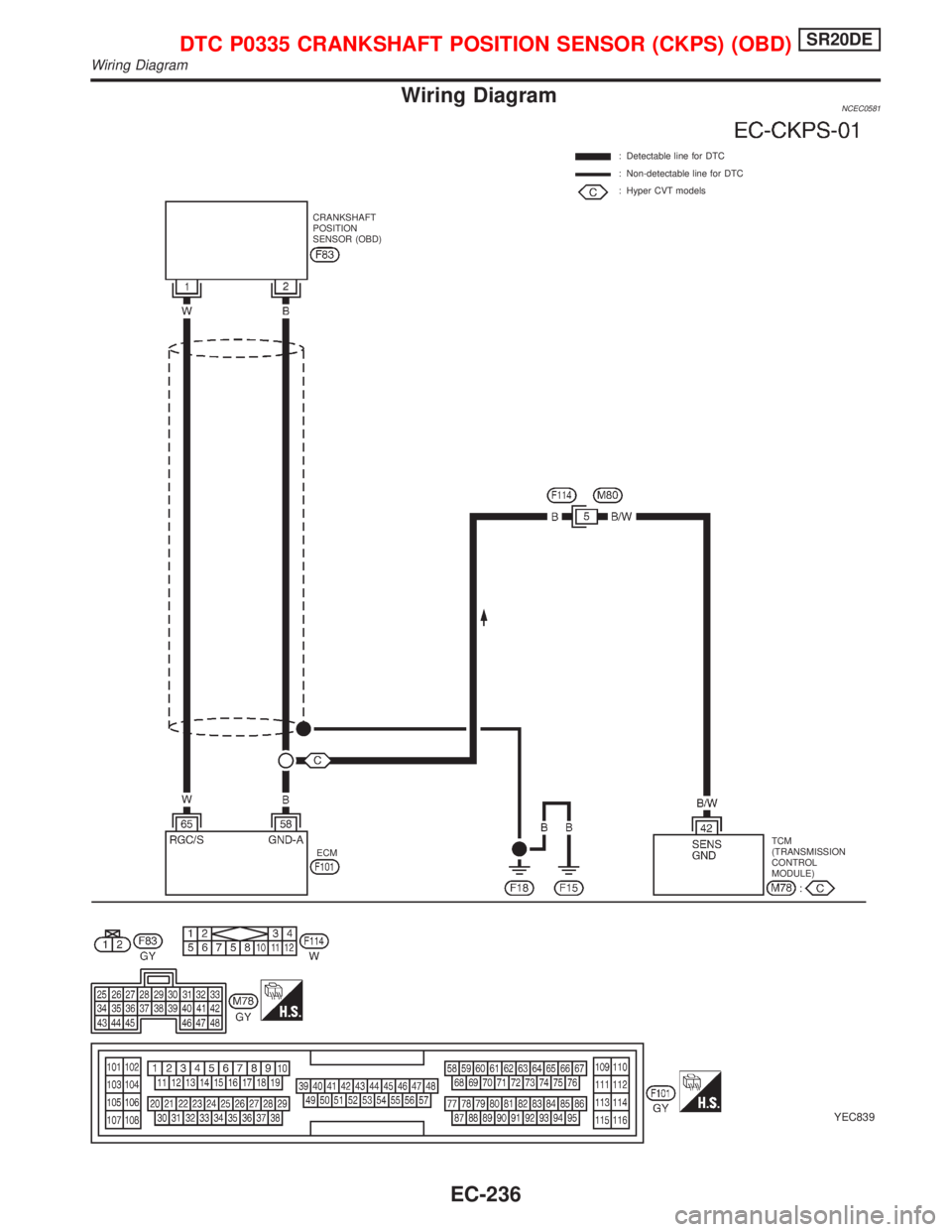
Wiring DiagramNCEC0581
YEC839
: Detectable line for DTC
: Non-detectable line for DTC
: Hyper CVT models
ECMTCM
(TRANSMISSION
CONTROL
MODULE) CRANKSHAFT
POSITION
SENSOR (OBD)
DTC P0335 CRANKSHAFT POSITION SENSOR (CKPS) (OBD)SR20DE
Wiring Diagram
EC-236
Page 1037 of 2267
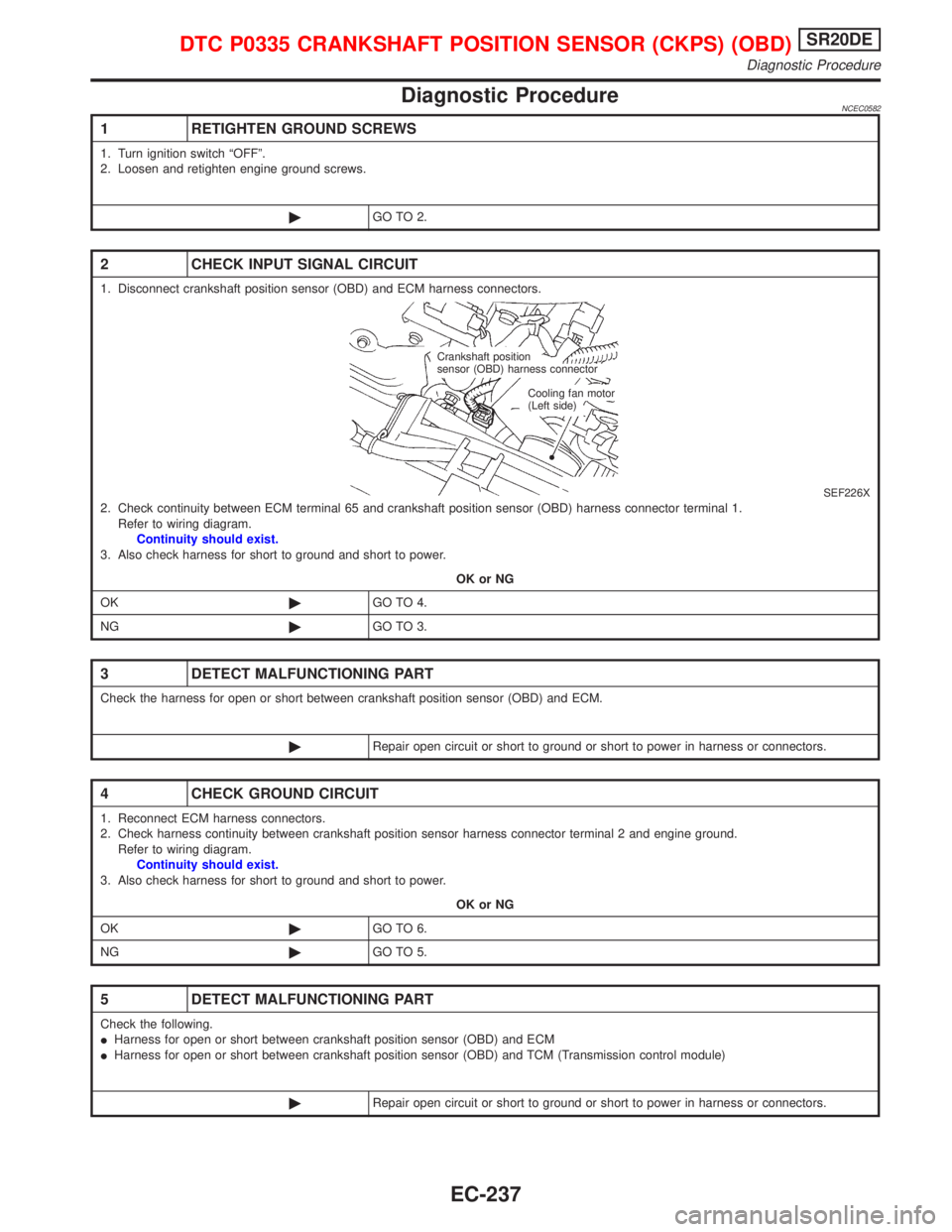
Diagnostic ProcedureNCEC0582
1 RETIGHTEN GROUND SCREWS
1. Turn ignition switch ªOFFº.
2. Loosen and retighten engine ground screws.
©GO TO 2.
2 CHECK INPUT SIGNAL CIRCUIT
1. Disconnect crankshaft position sensor (OBD) and ECM harness connectors.
SEF226X2. Check continuity between ECM terminal 65 and crankshaft position sensor (OBD) harness connector terminal 1.
Refer to wiring diagram.
Continuity should exist.
3. Also check harness for short to ground and short to power.
OK or NG
OK©GO TO 4.
NG©GO TO 3.
3 DETECT MALFUNCTIONING PART
Check the harness for open or short between crankshaft position sensor (OBD) and ECM.
©Repair open circuit or short to ground or short to power in harness or connectors.
4 CHECK GROUND CIRCUIT
1. Reconnect ECM harness connectors.
2. Check harness continuity between crankshaft position sensor harness connector terminal 2 and engine ground.
Refer to wiring diagram.
Continuity should exist.
3. Also check harness for short to ground and short to power.
OK or NG
OK©GO TO 6.
NG©GO TO 5.
5 DETECT MALFUNCTIONING PART
Check the following.
IHarness for open or short between crankshaft position sensor (OBD) and ECM
IHarness for open or short between crankshaft position sensor (OBD) and TCM (Transmission control module)
©Repair open circuit or short to ground or short to power in harness or connectors.
Crankshaft position
sensor (OBD) harness connector
Cooling fan motor
(Left side)
DTC P0335 CRANKSHAFT POSITION SENSOR (CKPS) (OBD)SR20DE
Diagnostic Procedure
EC-237
Page 1038 of 2267
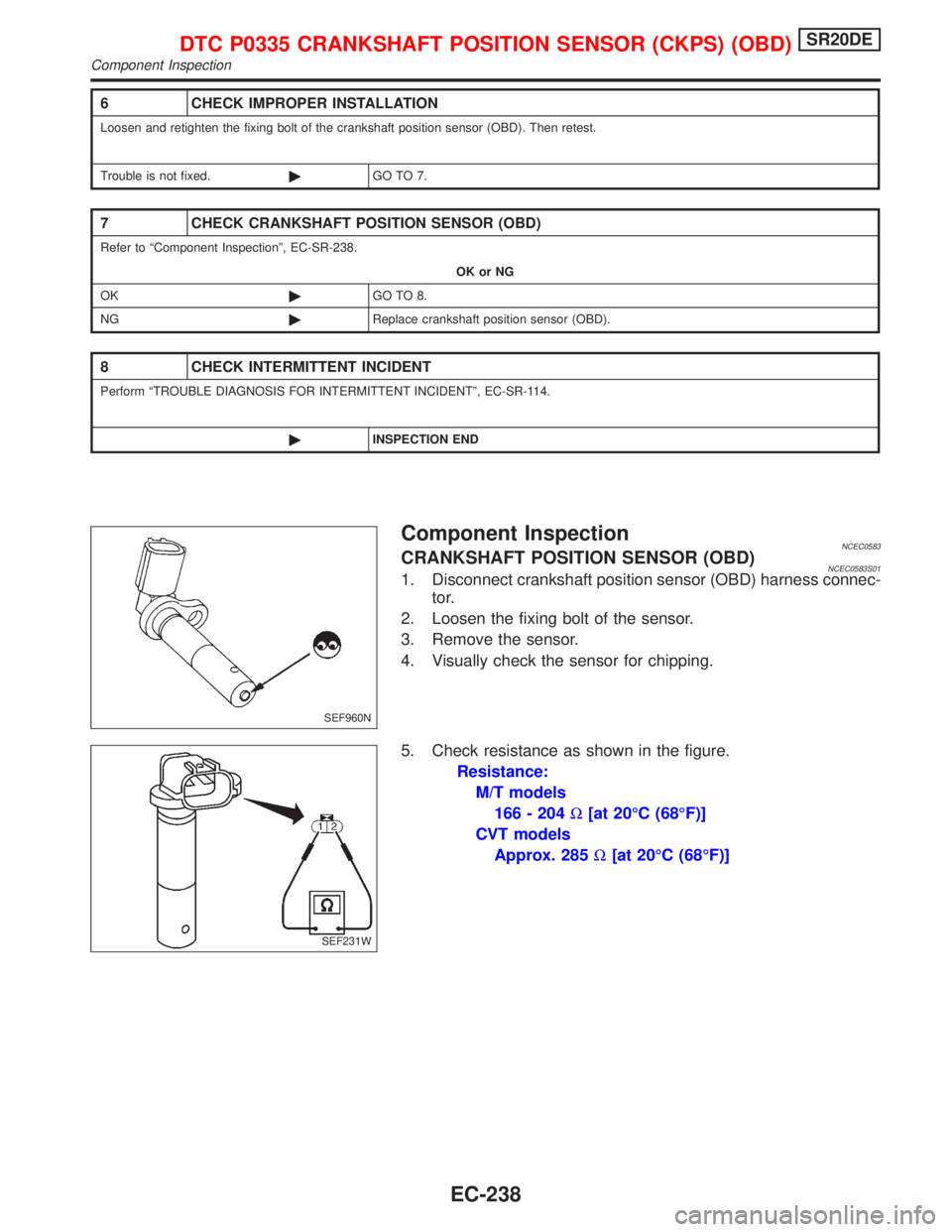
Component InspectionNCEC0583CRANKSHAFT POSITION SENSOR (OBD)NCEC0583S011. Disconnect crankshaft position sensor (OBD) harness connec-
tor.
2. Loosen the fixing bolt of the sensor.
3. Remove the sensor.
4. Visually check the sensor for chipping.
5. Check resistance as shown in the figure.
Resistance:
M/T models
166 - 204W[at 20ÉC (68ÉF)]
CVT models
Approx. 285W[at 20ÉC (68ÉF)]
6 CHECK IMPROPER INSTALLATION
Loosen and retighten the fixing bolt of the crankshaft position sensor (OBD). Then retest.
Trouble is not fixed.©GO TO 7.
7 CHECK CRANKSHAFT POSITION SENSOR (OBD)
Refer to ªComponent Inspectionº, EC-SR-238.
OK or NG
OK©GO TO 8.
NG©Replace crankshaft position sensor (OBD).
8 CHECK INTERMITTENT INCIDENT
Perform ªTROUBLE DIAGNOSIS FOR INTERMITTENT INCIDENTº, EC-SR-114.
©INSPECTION END
SEF960N
SEF231W
DTC P0335 CRANKSHAFT POSITION SENSOR (CKPS) (OBD)SR20DE
Component Inspection
EC-238
Page 1039 of 2267
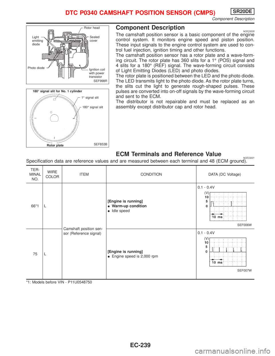
Component DescriptionNCEC0220The camshaft position sensor is a basic component of the engine
control system. It monitors engine speed and piston position.
These input signals to the engine control system are used to con-
trol fuel injection, ignition timing and other functions.
The camshaft position sensor has a rotor plate and a wave-form-
ing circuit. The rotor plate has 360 slits for a 1É (POS) signal and
4 slits for a 180É (REF) signal. The wave-forming circuit consists
of Light Emitting Diodes (LED) and photo diodes.
The rotor plate is positioned between the LED and the photo diode.
The LED transmits light to the photo diode. As the rotor plate turns,
the slits cut the light to generate rough-shaped pulses. These
pulses are converted into on-off signals by the wave-forming circuit
and sent to the ECM.
The distributor is not repairable and must be replaced as an
assembly except distributor cap and rotor head.
ECM Terminals and Reference ValueNCEC0221Specification data are reference values and are measured between each terminal and 48 (ECM ground).
TER-
MINAL
NO.WIRE
COLORITEM CONDITION DATA (DC Voltage)
66*1 L
Camshaft position sen-
sor (Reference signal)[Engine is running]
IWarm-up condition
IIdle speed0.1 - 0.4V
SEF006W
75 L[Engine is running]
IEngine speed is 2,000 rpm0.1 - 0.4V
SEF007W
*1: Models before VIN - P11U0548750
SEF998R Rotor head
Sealed
cover
Ignition coil
with power
transistor Light
emitting
diode
Photo diode
SEF853B 180É signal slit for No. 1 cylinder
1É signal slit
180É signal slit
Rotor plate
DTC P0340 CAMSHAFT POSITION SENSOR (CMPS)SR20DE
Component Description
EC-239
Page 1040 of 2267
![NISSAN PRIMERA 1999 Electronic Repair Manual TER-
MINAL
NO.WIRE
COLORITEM CONDITION DATA (DC Voltage)
85 B/WCamshaft position sen-
sor (Position signal)[Engine is running]
IWarm-up condition
IIdle speedApproximately 2.5V
0.2 ms
SEF004W
[Engine i NISSAN PRIMERA 1999 Electronic Repair Manual TER-
MINAL
NO.WIRE
COLORITEM CONDITION DATA (DC Voltage)
85 B/WCamshaft position sen-
sor (Position signal)[Engine is running]
IWarm-up condition
IIdle speedApproximately 2.5V
0.2 ms
SEF004W
[Engine i](/img/5/57377/w960_57377-1039.png)
TER-
MINAL
NO.WIRE
COLORITEM CONDITION DATA (DC Voltage)
85 B/WCamshaft position sen-
sor (Position signal)[Engine is running]
IWarm-up condition
IIdle speedApproximately 2.5V
0.2 ms
SEF004W
[Engine is running]
IEngine speed is 2,000 rpmApproximately 2.4V
0.2 ms
SEF005W
On Board Diagnosis LogicNCEC0222
DTC No. Malfunction is detected when ... Check Items (Possible Cause)
P0340
0340A) Either 1É or 180É signal is not sent to ECM for the
first few seconds during engine cranking.IHarness or connectors
(The camshaft position sensor circuit is open or
shorted.)
ICamshaft position sensor
IStarter motor (Refer to EL section.)
IStarting system circuit (Refer to EL section.)
IDead (Weak) battery B) Either 1É or 180É signal is not sent to ECM often
enough while the engine speed is higher than the
specified engine speed.
C) The relation between 1É and 180É signal is not in
the normal range during the specified engine speed.
DTC Confirmation ProcedureNCEC0223Perform ªProcedure for malfunction Aº first. If DTC cannot be
confirmed, perform ªProcedure for malfunction B and Cº.
NOTE:
If ªDTC Confirmation Procedureº has been previously conducted,
always turn ignition switch ªOFFº and wait at least 9 seconds
before conducting the next test.
TESTING CONDITION:
Before performing the following procedure, confirm that bat-
tery voltage is more than 10.5V.
PROCEDURE FOR MALFUNCTION ANCEC0223S01With CONSULT-II
1) Turn ignition switch ªONº.
2) Select ªDATA MONITORº mode with CONSULT-II.
3) Crank engine for at least 2 seconds.
4) If 1st trip DTC is detected, go to ªDiagnostic Procedureº, EC-
SR-243.
With GST
Follow the procedure ªWith CONSULT-IIº above.
NEF068A
DTC P0340 CAMSHAFT POSITION SENSOR (CMPS)SR20DE
ECM Terminals and Reference Value (Cont'd)
EC-240