NISSAN PRIMERA 1999 Electronic Repair Manual
Manufacturer: NISSAN, Model Year: 1999, Model line: PRIMERA, Model: NISSAN PRIMERA 1999Pages: 2267, PDF Size: 35.74 MB
Page 1951 of 2267
Maintenance of Lubricant Quantity in
Compressor
The lubricant used to lubricate the compressor circulates through
the system with the refrigerant. Add lubricant to compressor
when replacing any component or after a large gas leakage
occurred. It is important to maintain the specified amount.
If lubricant quantity is not maintained properly, the following mal-
functions may result:
lLack of lubricant: May lead to a seized compressor
lExcessive lubricant: Inadequate cooling (thermal exchange
interference)
LUBRICANT
CR-14
Name: Nissan A/C System Oil Type R
Part number: KLH00-PAGR0
CSV613
Name: Nissan A/C System Oil Type S
Part number: KLH00-PAGS0
CHECKING AND ADJUSTING
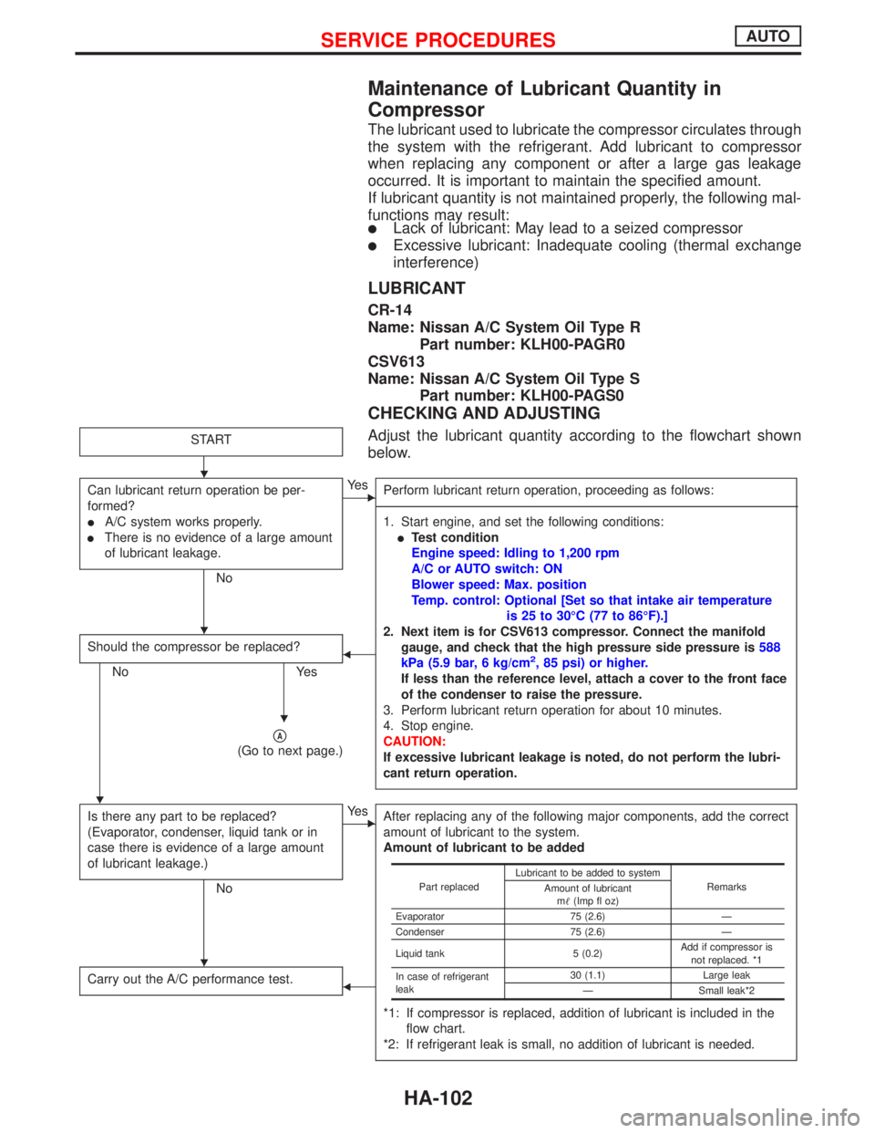
Adjust the lubricant quantity according to the flowchart shown
below.START
Can lubricant return operation be per-
formed?
lA/C system works properly.
lThere is no evidence of a large amount
of lubricant leakage.
No
EYe s
Perform lubricant return operation, proceeding as follows:
------------------------------------------------------------------------------------------------------------------------------------------------------------------------------------------------------------------------------------------------------------------------------------------------------------------------------------------------------------------------------------------------------------------------------------------------------------------------------------------------------------------------------------
1. Start engine, and set the following conditions:
lTest condition
Engine speed: Idling to 1,200 rpm
A/C or AUTO switch: ON
Blower speed: Max. position
Temp. control: Optional [Set so that intake air temperature
is 25 to 30ÉC (77 to 86ÉF).]
2. Next item is for CSV613 compressor. Connect the manifold
gauge, and check that the high pressure side pressure is588
kPa (5.9 bar, 6 kg/cm
2, 85 psi) or higher.
If less than the reference level, attach a cover to the front face
of the condenser to raise the pressure.
3. Perform lubricant return operation for about 10 minutes.
4. Stop engine.
CAUTION:
If excessive lubricant leakage is noted, do not perform the lubri-
cant return operation.
Should the compressor be replaced?
No Yes
F
pA
(Go to next page.)
Is there any part to be replaced?
(Evaporator, condenser, liquid tank or in
case there is evidence of a large amount
of lubricant leakage.)
No
EYe s
After replacing any of the following major components, add the correct
amount of lubricant to the system.
Amount of lubricant to be added
*1: If compressor is replaced, addition of lubricant is included in the
flow chart.
*2: If refrigerant leak is small, no addition of lubricant is needed.
Carry out the A/C performance test.F
Part replacedLubricant to be added to system
Remarks
Amount of lubricant
m(Imp fl oz)
Evaporator 75 (2.6) Ð
Condenser 75 (2.6) Ð
Liquid tank 5 (0.2)Add if compressor is
not replaced. *1
In case of refrigerant
leak30 (1.1) Large leak
Ð Small leak*2
H
H
H
H
H
SERVICE PROCEDURESAUTO
HA-102
Page 1952 of 2267
pA
H
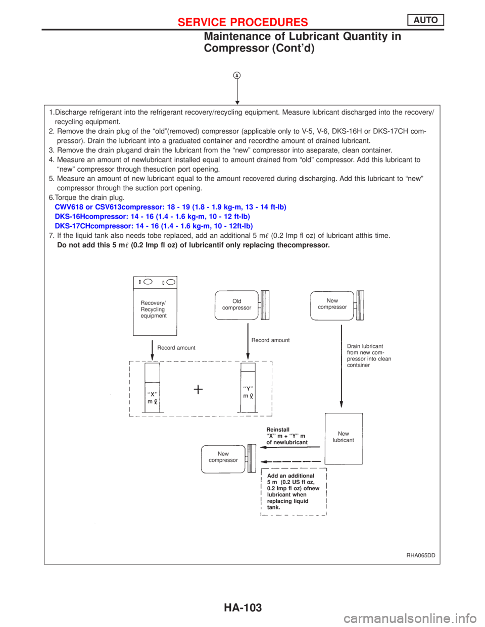
1.Discharge refrigerant into the refrigerant recovery/recycling equipment. Measure lubricant discharged into the recovery/
recycling equipment.
2. Remove the drain plug of the ªoldº(removed) compressor (applicable only to V-5, V-6, DKS-16H or DKS-17CH com-
pressor). Drain the lubricant into a graduated container and recordthe amount of drained lubricant.
3. Remove the drain plugand drain the lubricant from the ªnewº compressor into aseparate, clean container.
4. Measure an amount of newlubricant installed equal to amount drained from ªoldº compressor. Add this lubricant to
ªnewº compressor through thesuction port opening.
5. Measure an amount of new lubricant equal to the amount recovered during discharging. Add this lubricant to ªnewº
compressor through the suction port opening.
6.Torque the drain plug.
CWV618 or CSV613compressor: 18 - 19 (1.8 - 1.9 kg-m, 13 - 14 ft-lb)
DKS-16Hcompressor: 14 - 16 (1.4 - 1.6 kg-m, 10 - 12 ft-lb)
DKS-17CHcompressor: 14 - 16 (1.4 - 1.6 kg-m, 10 - 12ft-lb)
7. If the liquid tank also needs tobe replaced, add an additional 5 m(0.2 Imp fl oz) of lubricant atthis time.
Do not add this 5 m(0.2 Imp fl oz) of lubricantif only replacing thecompressor.
RHA065DD
Recovery/
Recycling
equipmentOld
compressorNew
compressor
Record amountRecord amount
Drain lubricant
from new com-
pressor into clean
container
Reinstall
ªXº m + ªYº m
of newlubricantNew
lubricant
New
compressor
Add an additional
5 m (0.2 US fl oz,
0.2 Imp fl oz) ofnew
lubricant when
replacing liquid
tank.
SERVICE PROCEDURESAUTO
Maintenance of Lubricant Quantity in
Compressor (Cont'd)
HA-103
Page 1953 of 2267
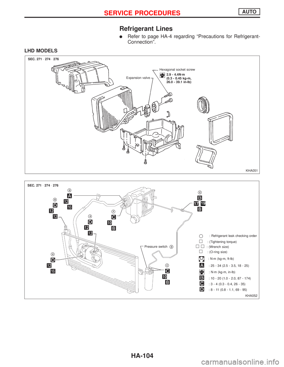
Refrigerant Lines
lRefer to page HA-4 regarding ªPrecautions for Refrigerant-
Connectionº.
LHD MODELS
KHA051 Expansion valveHexagonal socket screw
2.9 - 4.4N´m
(0.3 - 0.45 kg-m,
26.0 - 39.1 in-lb) SEC. 271×274×276
KHA052 SEC. 271×274×276
pG
pB
pH
pApF
Pressure switchpD
pC
pE
p: Refrigerant leak checking order
l: (Tightening torque)
ll: (Wrench size)
l: (O-ring size)
: N´m (kg-m, ft-lb)
: 25 - 34 (2.5 - 3.5, 18 - 25)
: N´m (kg-m, in-lb)
: 10 - 20 (1.0 - 2.0, 87 - 174)
:3-4(0.3 - 0.4, 26 - 35)
:8-11(0.8 - 1.1, 69 - 95)
1719
SERVICE PROCEDURESAUTO
HA-104
Page 1954 of 2267
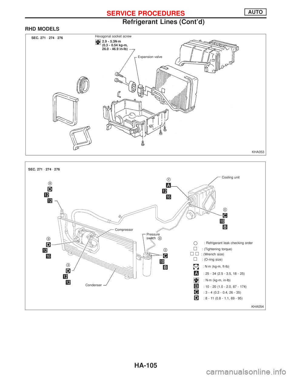
RHD MODELS
KHA053 SEC. 271×274×276Hexagonal socket screw
2.9 - 5.3N´m
(0.3 - 0.54 kg-m,
26.0 - 46.9 in-lb)
Expansion valve
KHA054 SEC. 271×274×276
pB
pG
pA
Compressor
CondenserPressure
switch
pD
pC
pFCooling unit
pE
p: Refrigerant leak checking order
l: (Tightening torque)
ll: (Wrench size)
l: (O-ring size)
: N´m (kg-m, ft-lb)
: 25 - 34 (2.5 - 3.5, 18 - 25)
: N´m (kg-m, in-lb)
: 10 - 20 (1.0 - 2.0, 87 - 174)
:3-4(0.3 - 0.4, 26 - 35)
:8-11(0.8 - 1.1, 69 - 95)
SERVICE PROCEDURESAUTO
Refrigerant Lines (Cont'd)
HA-105
Page 1955 of 2267
Checking Refrigerant Leaks
PRELIMINARY CHECK
Perform a visual inspection of all refrigeration parts, fittings,
hoses, and components for signs of A/C lubricant leakage, dam-
age and corrosion.
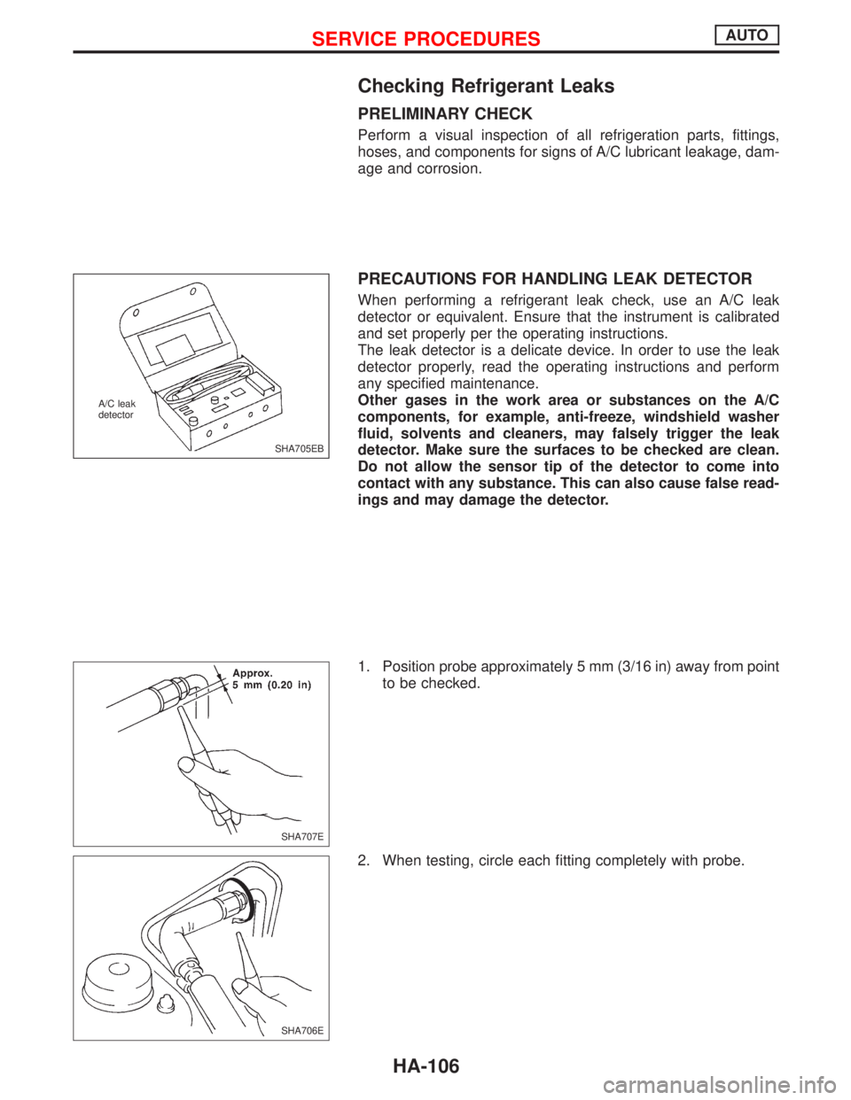
PRECAUTIONS FOR HANDLING LEAK DETECTOR
When performing a refrigerant leak check, use an A/C leak
detector or equivalent. Ensure that the instrument is calibrated
and set properly per the operating instructions.
The leak detector is a delicate device. In order to use the leak
detector properly, read the operating instructions and perform
any specified maintenance.
Other gases in the work area or substances on the A/C
components, for example, anti-freeze, windshield washer
fluid, solvents and cleaners, may falsely trigger the leak
detector. Make sure the surfaces to be checked are clean.
Do not allow the sensor tip of the detector to come into
contact with any substance. This can also cause false read-
ings and may damage the detector.
1. Position probe approximately 5 mm (3/16 in) away from point
to be checked.
2. When testing, circle each fitting completely with probe.
SHA705EB A/C leak
detector
SHA707E
SHA706E
SERVICE PROCEDURESAUTO
HA-106
Page 1956 of 2267
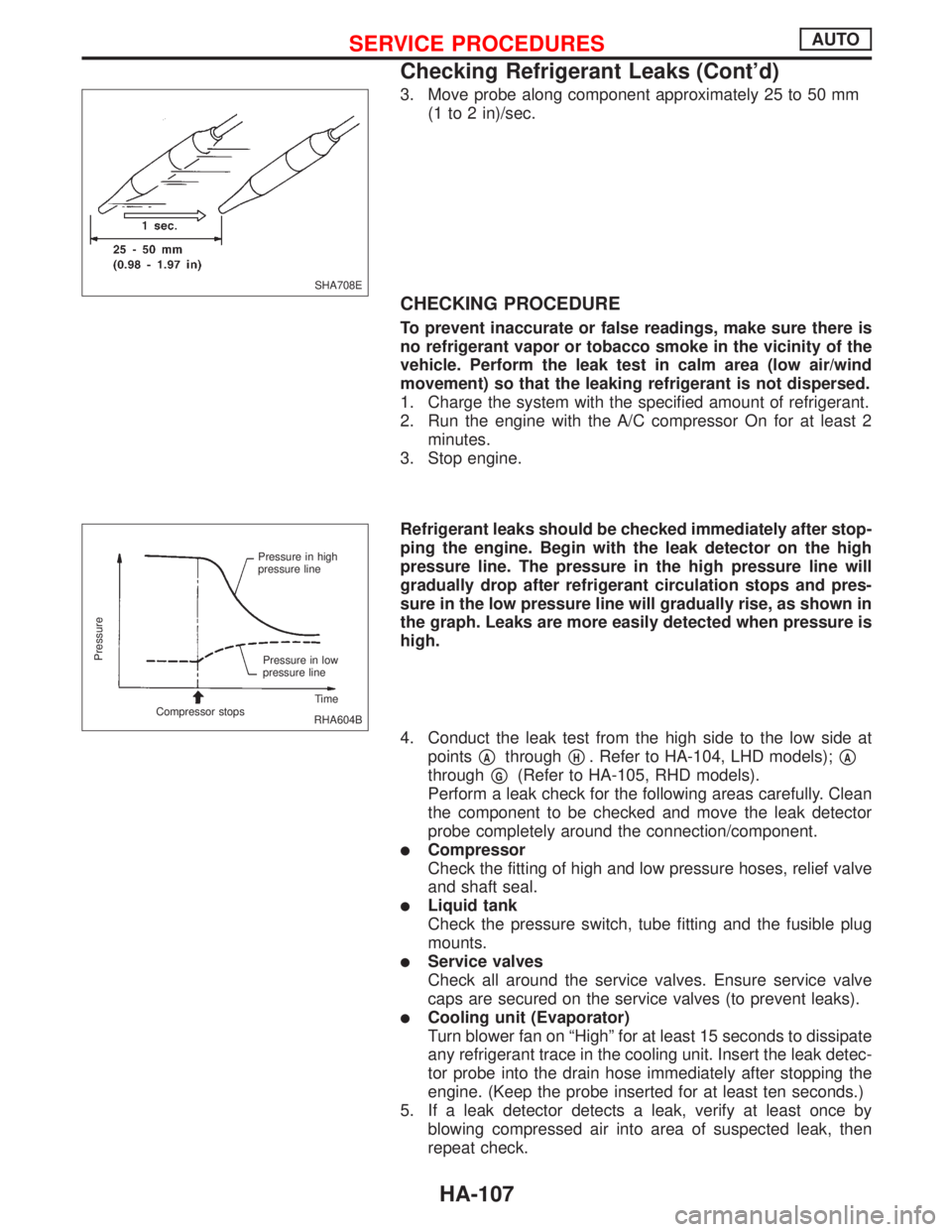
3. Move probe along component approximately 25 to 50 mm
(1 to 2 in)/sec.
CHECKING PROCEDURE
To prevent inaccurate or false readings, make sure there is
no refrigerant vapor or tobacco smoke in the vicinity of the
vehicle. Perform the leak test in calm area (low air/wind
movement) so that the leaking refrigerant is not dispersed.
1. Charge the system with the specified amount of refrigerant.
2. Run the engine with the A/C compressor On for at least 2
minutes.
3. Stop engine.
Refrigerant leaks should be checked immediately after stop-
ping the engine. Begin with the leak detector on the high
pressure line. The pressure in the high pressure line will
gradually drop after refrigerant circulation stops and pres-
sure in the low pressure line will gradually rise, as shown in
the graph. Leaks are more easily detected when pressure is
high.
4. Conduct the leak test from the high side to the low side at
points
pAthroughpH. Refer to HA-104, LHD models);pA
throughpG(Refer to HA-105, RHD models).
Perform a leak check for the following areas carefully. Clean
the component to be checked and move the leak detector
probe completely around the connection/component.
lCompressor
Check the fitting of high and low pressure hoses, relief valve
and shaft seal.
lLiquid tank
Check the pressure switch, tube fitting and the fusible plug
mounts.
lService valves
Check all around the service valves. Ensure service valve
caps are secured on the service valves (to prevent leaks).
lCooling unit (Evaporator)
Turn blower fan on ªHighº for at least 15 seconds to dissipate
any refrigerant trace in the cooling unit. Insert the leak detec-
tor probe into the drain hose immediately after stopping the
engine. (Keep the probe inserted for at least ten seconds.)
5. If a leak detector detects a leak, verify at least once by
blowing compressed air into area of suspected leak, then
repeat check.
SHA708E
RHA604B Pressure in high
pressure line
Pressure in low
pressure line
Time
Compressor stops
Pressure
SERVICE PROCEDURESAUTO
Checking Refrigerant Leaks (Cont'd)
HA-107
Page 1957 of 2267

6. Do not stop when one leak is found. Continue to check for
additional leaks at all system components.
7. Start engine.
SERVICE PROCEDURESAUTO
Checking Refrigerant Leaks (Cont'd)
HA-108
Page 1958 of 2267
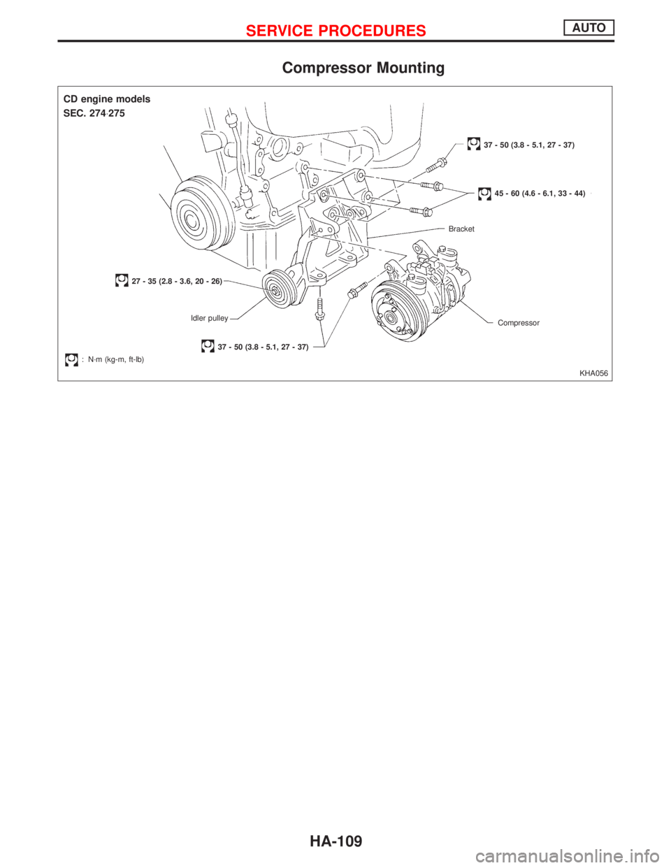
Compressor Mounting
KHA056
CD engine models
27 - 35 (2.8 - 3.6, 20 - 26)
Idler pulley
.: N´m (kg-m, ft-lb)
37 - 50 (3.8 - 5.1, 27 - 37)Compressor Bracket
45 - 60 (4.6 - 6.1, 33 - 44)
37 - 50 (3.8 - 5.1, 27 - 37)
SEC. 274×275
SERVICE PROCEDURESAUTO
HA-109
Page 1959 of 2267
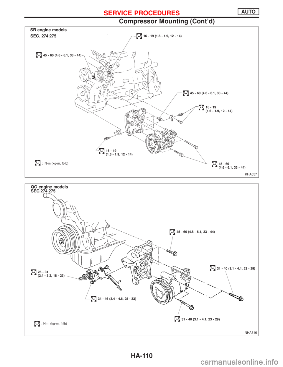
KHA057
SR engine models
45 - 60 (4.6 - 6.1, 33 - 44)
16 - 19 (1.6 - 1.9, 12 - 14)
45 - 60 (4.6 - 6.1, 33 - 44)
16-19
(1.6 - 1.9, 12 - 14)
45-60
(4.6 - 6.1, 33 - 44): N´m (kg-m, ft-lb)
16-19
(1.6 - 1.9, 12 - 14)
SEC. 274×275
NHA316
QG engine models
SEC.274×275
25-31
(2.4 - 3.2, 18 - 23)
34 - 46 (3.4 - 4.6, 25 - 33)
: N´m (kg-m, ft-lb)31 - 40 (3.1 - 4.1, 23 - 29)
31 - 40 (3.1 - 4.1, 23 - 29)
45 - 60 (4.6 - 6.1, 33 - 44)
SERVICE PROCEDURESAUTO
Compressor Mounting (Cont'd)
HA-110
Page 1960 of 2267
Belt tension
lRefer to MA section.
Fast Idle Control Device (FICD)
lrefer to EC section.
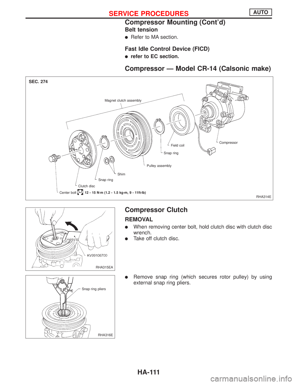
Compressor Ð Model CR-14 (Calsonic make)
Compressor Clutch
REMOVAL
lWhen removing center bolt, hold clutch disc with clutch disc
wrench.
lTake off clutch disc.
lRemove snap ring (which secures rotor pulley) by using
external snap ring pliers.
RHA314E Magnet clutch assembly
Compressor
Field coil
Snap ring
Pulley assembly
Clutch discShim
Snap ring
Center bolt12 - 15 N´m (1.2 - 1.5 kg-m,9-11ft-lb)
SEC. 274
RHA315EA
RHA316E Snap ring pliers
SERVICE PROCEDURESAUTO
Compressor Mounting (Cont'd)
HA-111