NISSAN PRIMERA 1999 Electronic Repair Manual
Manufacturer: NISSAN, Model Year: 1999, Model line: PRIMERA, Model: NISSAN PRIMERA 1999Pages: 2267, PDF Size: 35.74 MB
Page 1931 of 2267
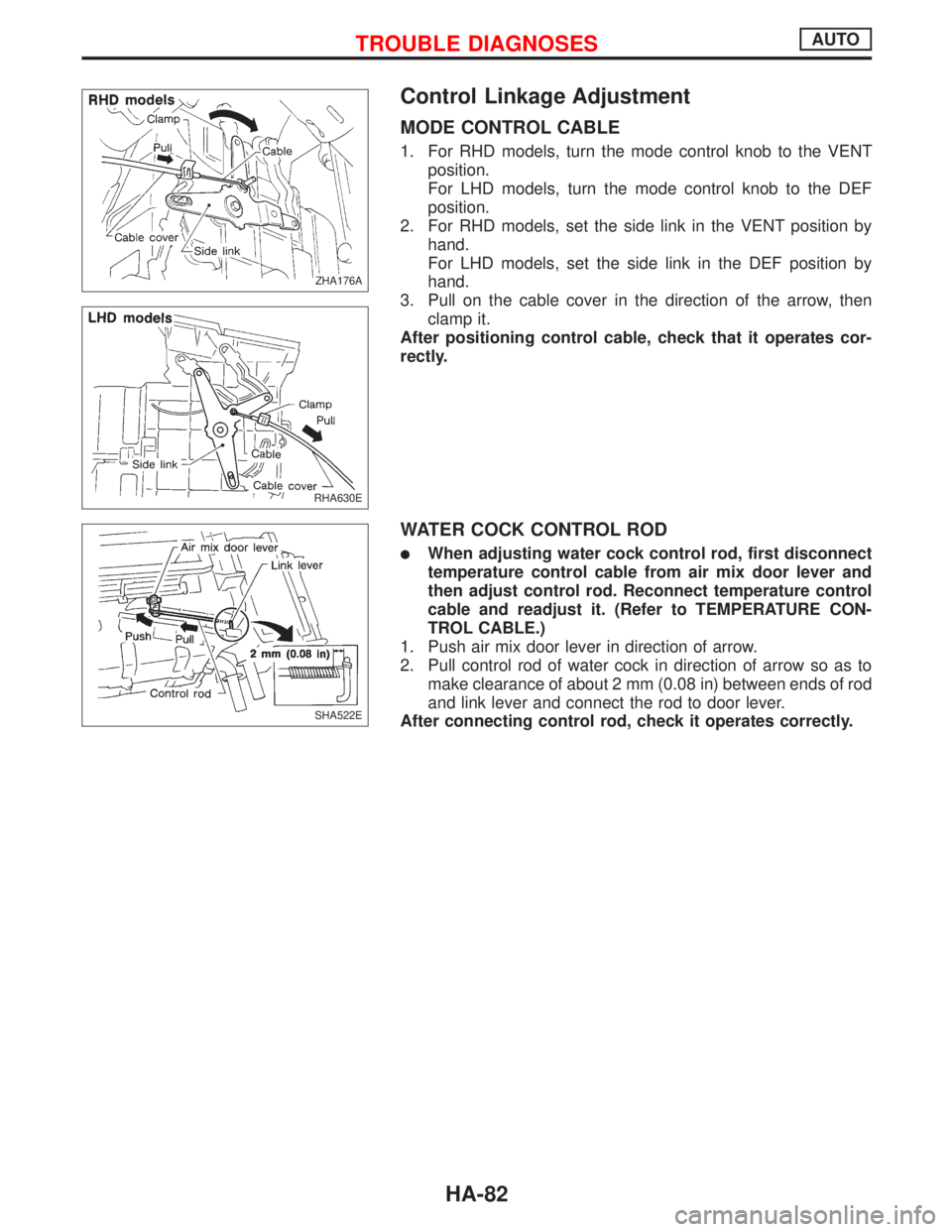
Control Linkage Adjustment
MODE CONTROL CABLE
1. For RHD models, turn the mode control knob to the VENT
position.
For LHD models, turn the mode control knob to the DEF
position.
2. For RHD models, set the side link in the VENT position by
hand.
For LHD models, set the side link in the DEF position by
hand.
3. Pull on the cable cover in the direction of the arrow, then
clamp it.
After positioning control cable, check that it operates cor-
rectly.
WATER COCK CONTROL ROD
lWhen adjusting water cock control rod, first disconnect
temperature control cable from air mix door lever and
then adjust control rod. Reconnect temperature control
cable and readjust it. (Refer to TEMPERATURE CON-
TROL CABLE.)
1. Push air mix door lever in direction of arrow.
2. Pull control rod of water cock in direction of arrow so as to
make clearance of about 2 mm (0.08 in) between ends of rod
and link lever and connect the rod to door lever.
After connecting control rod, check it operates correctly.
ZHA176A.ZHA176A
RHA630E
SHA522E
TROUBLE DIAGNOSESAUTO
HA-82
Page 1932 of 2267
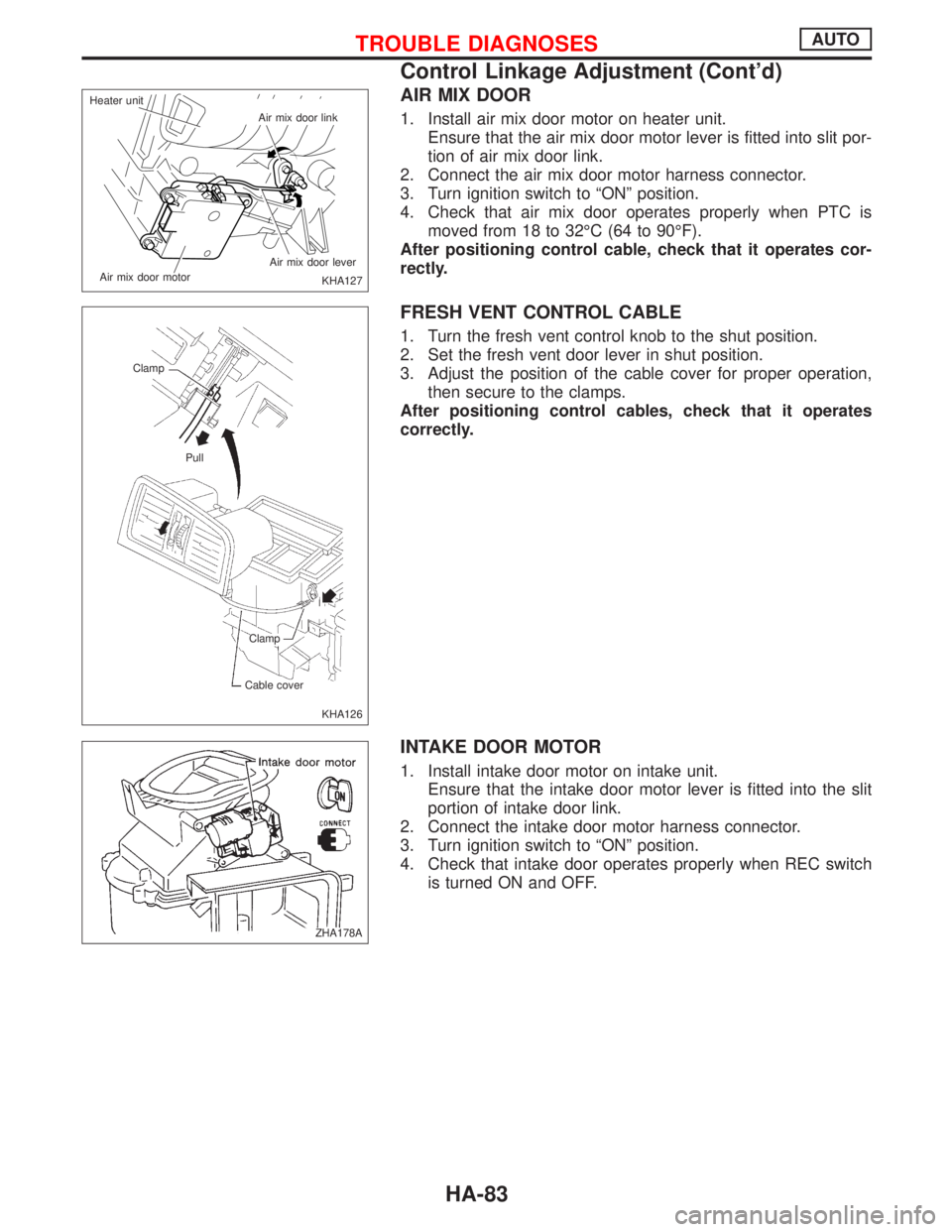
AIR MIX DOOR
1. Install air mix door motor on heater unit.
Ensure that the air mix door motor lever is fitted into slit por-
tion of air mix door link.
2. Connect the air mix door motor harness connector.
3. Turn ignition switch to ªONº position.
4. Check that air mix door operates properly when PTC is
moved from 18 to 32ÉC (64 to 90ÉF).
After positioning control cable, check that it operates cor-
rectly.
FRESH VENT CONTROL CABLE
1. Turn the fresh vent control knob to the shut position.
2. Set the fresh vent door lever in shut position.
3. Adjust the position of the cable cover for proper operation,
then secure to the clamps.
After positioning control cables, check that it operates
correctly.
INTAKE DOOR MOTOR
1. Install intake door motor on intake unit.
Ensure that the intake door motor lever is fitted into the slit
portion of intake door link.
2. Connect the intake door motor harness connector.
3. Turn ignition switch to ªONº position.
4. Check that intake door operates properly when REC switch
is turned ON and OFF.
KHA127 Air mix door link
Air mix door lever
Air mix door motor Heater unit
KHA126 Clamp
Pull
Clamp
Cable cover
ZHA178A
TROUBLE DIAGNOSESAUTO
Control Linkage Adjustment (Cont'd)
HA-83
Page 1933 of 2267
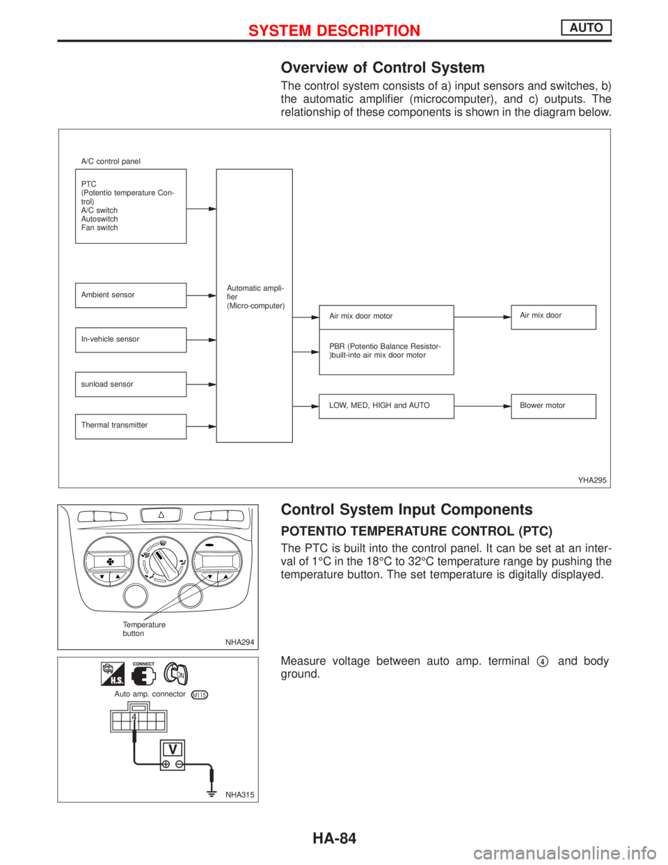
Overview of Control System
The control system consists of a) input sensors and switches, b)
the automatic amplifier (microcomputer), and c) outputs. The
relationship of these components is shown in the diagram below.
Control System Input Components
POTENTIO TEMPERATURE CONTROL (PTC)
The PTC is built into the control panel. It can be set at an inter-
val of 1ÉC in the 18ÉC to 32ÉC temperature range by pushing the
temperature button. The set temperature is digitally displayed.
Measure voltage between auto amp. terminal
p4and body
ground.
YHA295 A/C control panel
PTC
(Potentio temperature Con-
trol)
A/C switch
Autoswitch
Fan switch
Ambient sensor
In-vehicle sensor
sunload sensor
Thermal transmitterAutomatic ampli-
fier
(Micro-computer)
Air mix door motor
PBR (Potentio Balance Resistor-
)built-into air mix door motor
LOW, MED, HIGH and AUTOAir mix door
Blower motor
NHA294 Temperature
button
NHA315 Auto amp. connector
SYSTEM DESCRIPTIONAUTO
HA-84
Page 1934 of 2267
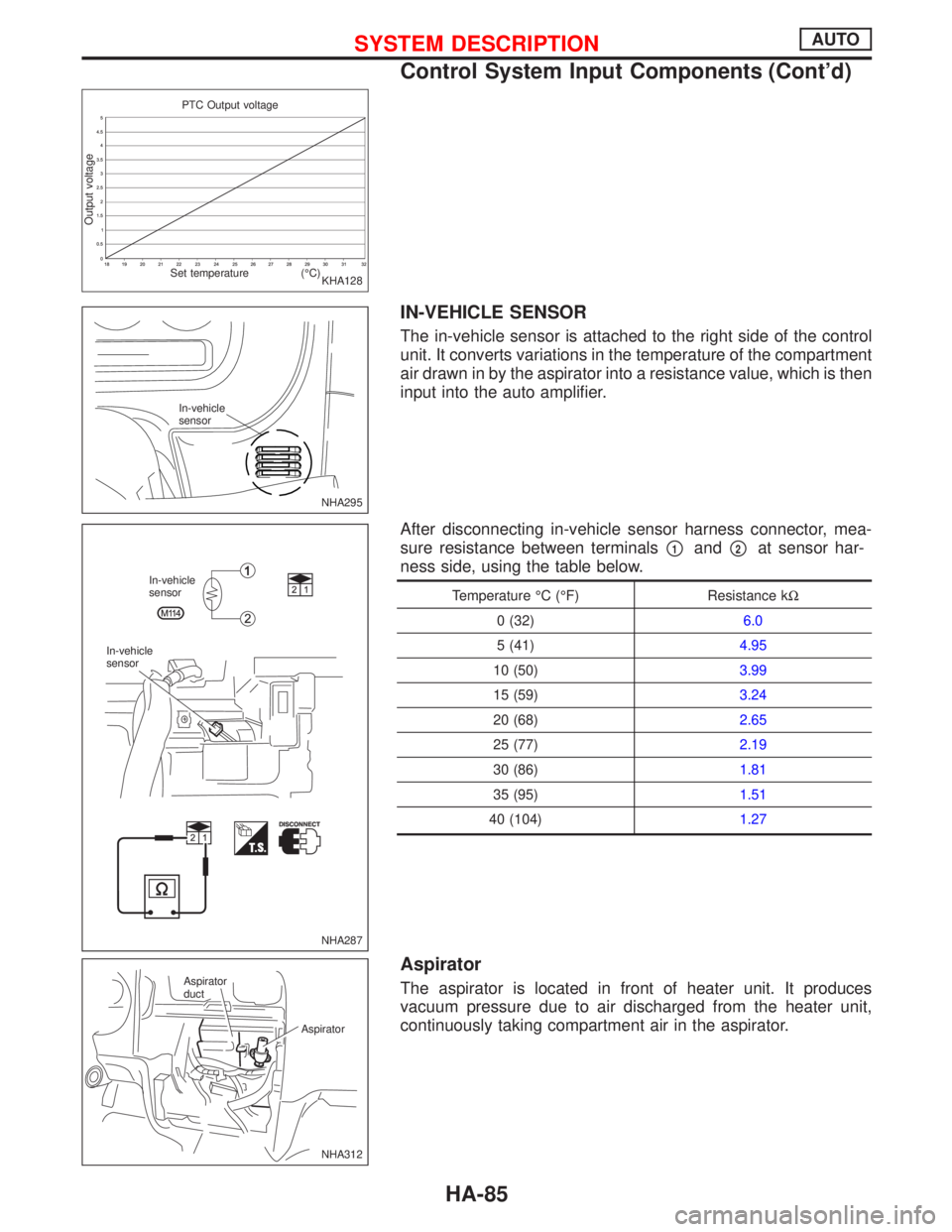
IN-VEHICLE SENSOR
The in-vehicle sensor is attached to the right side of the control
unit. It converts variations in the temperature of the compartment
air drawn in by the aspirator into a resistance value, which is then
input into the auto amplifier.
After disconnecting in-vehicle sensor harness connector, mea-
sure resistance between terminals
p1andp2at sensor har-
ness side, using the table below.
Temperature ÉC (ÉF) Resistance kW
0 (32)6.0
5 (41)4.95
10 (50)3.99
15 (59)3.24
20 (68)2.65
25 (77)2.19
30 (86)1.81
35 (95)1.51
40 (104)1.27
Aspirator
The aspirator is located in front of heater unit. It produces
vacuum pressure due to air discharged from the heater unit,
continuously taking compartment air in the aspirator.
KHA128 PTC Output voltage
Set temperature (ÉC)
Output voltage
NHA295 In-vehicle
sensor
NHA287 In-vehicle
sensor
In-vehicle
sensor
NHA312 Aspirator
duct
Aspirator
SYSTEM DESCRIPTIONAUTO
Control System Input Components (Cont'd)
HA-85
Page 1935 of 2267
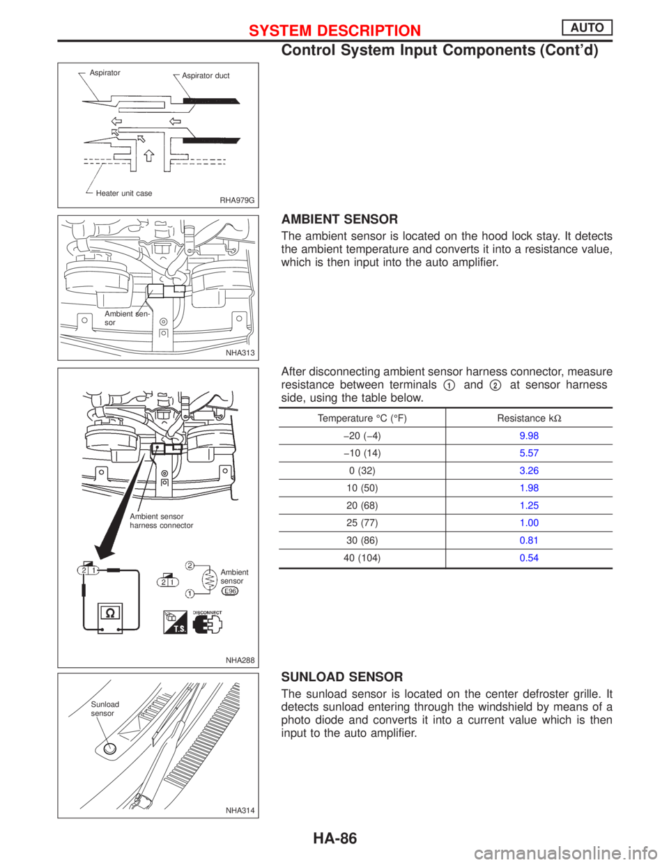
AMBIENT SENSOR
The ambient sensor is located on the hood lock stay. It detects
the ambient temperature and converts it into a resistance value,
which is then input into the auto amplifier.
After disconnecting ambient sensor harness connector, measure
resistance between terminals
p1andp2at sensor harness
side, using the table below.
Temperature ÉC (ÉF) Resistance kW
þ20 (þ4)9.98
þ10 (14)5.57
0 (32)3.26
10 (50)1.98
20 (68)1.25
25 (77)1.00
30 (86)0.81
40 (104)0.54
SUNLOAD SENSOR
The sunload sensor is located on the center defroster grille. It
detects sunload entering through the windshield by means of a
photo diode and converts it into a current value which is then
input to the auto amplifier.
RHA979G Aspirator
Aspirator duct
Heater unit case
NHA313 Ambient sen-
sor
NHA288 Ambient sensor
harness connector
Ambient
sensor
NHA314 Sunload
sensor
SYSTEM DESCRIPTIONAUTO
Control System Input Components (Cont'd)
HA-86
Page 1936 of 2267
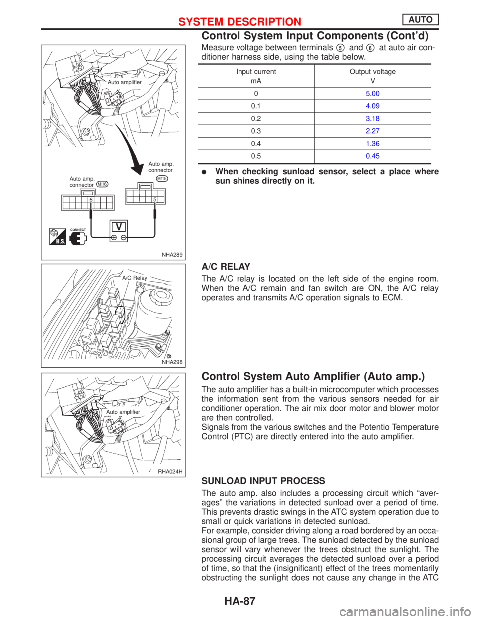
Measure voltage between terminalsp5andp6at auto air con-
ditioner harness side, using the table below.
Input current
mAOutput voltage
V
05.00
0.14.09
0.23.18
0.32.27
0.41.36
0.50.45
lWhen checking sunload sensor, select a place where
sun shines directly on it.
A/C RELAY
The A/C relay is located on the left side of the engine room.
When the A/C remain and fan switch are ON, the A/C relay
operates and transmits A/C operation signals to ECM.
Control System Auto Amplifier (Auto amp.)
The auto amplifier has a built-in microcomputer which processes
the information sent from the various sensors needed for air
conditioner operation. The air mix door motor and blower motor
are then controlled.
Signals from the various switches and the Potentio Temperature
Control (PTC) are directly entered into the auto amplifier.
SUNLOAD INPUT PROCESS
The auto amp. also includes a processing circuit which ªaver-
agesº the variations in detected sunload over a period of time.
This prevents drastic swings in the ATC system operation due to
small or quick variations in detected sunload.
For example, consider driving along a road bordered by an occa-
sional group of large trees. The sunload detected by the sunload
sensor will vary whenever the trees obstruct the sunlight. The
processing circuit averages the detected sunload over a period
of time, so that the (insignificant) effect of the trees momentarily
obstructing the sunlight does not cause any change in the ATC
NHA289 Auto amplifier
Auto amp.
connectorAuto amp.
connector
NHA298
.A/C Relay
RHA024H Auto amplifier
SYSTEM DESCRIPTIONAUTO
Control System Input Components (Cont'd)
HA-87
Page 1937 of 2267
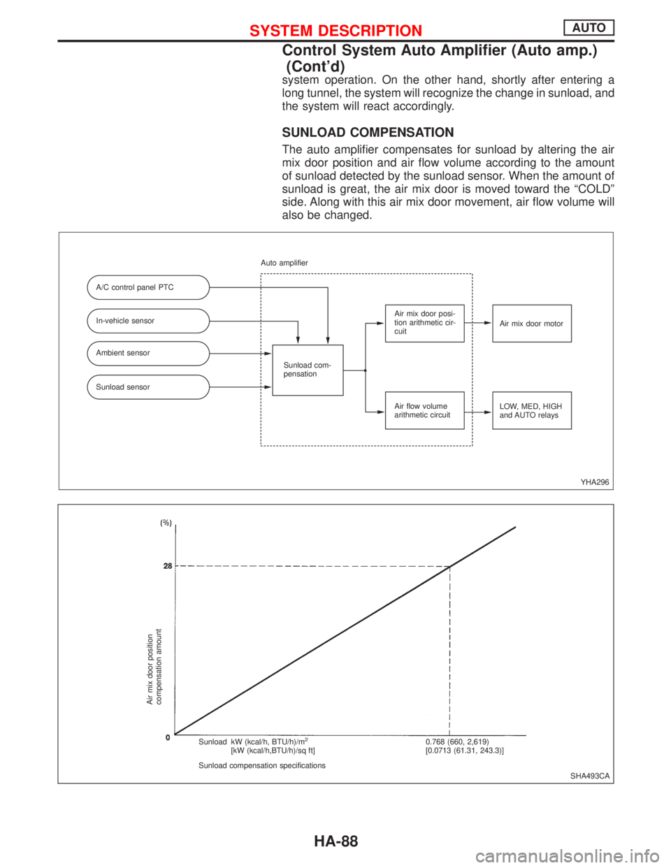
system operation. On the other hand, shortly after entering a
long tunnel, the system will recognize the change in sunload, and
the system will react accordingly.
SUNLOAD COMPENSATION
The auto amplifier compensates for sunload by altering the air
mix door position and air flow volume according to the amount
of sunload detected by the sunload sensor. When the amount of
sunload is great, the air mix door is moved toward the ªCOLDº
side. Along with this air mix door movement, air flow volume will
also be changed.
YHA296 A/C control panel PTC
In-vehicle sensor
Ambient sensor
Sunload sensorSunload com-
pensation Auto amplifier
Air mix door posi-
tion arithmetic cir-
cuit
Air flow volume
arithmetic circuitAir mix door motor
LOW, MED, HIGH
and AUTO relays
SHA493CA
Air mix door position
compensation amount
Sunload kW (kcal/h, BTU/h)/m2
[kW (kcal/h,BTU/h)/sq ft]
Sunload compensation specifications0.768 (660, 2,619)
[0.0713 (61.31, 243.3)]
SYSTEM DESCRIPTIONAUTO
Control System Auto Amplifier (Auto amp.)
(Cont'd)
HA-88
Page 1938 of 2267
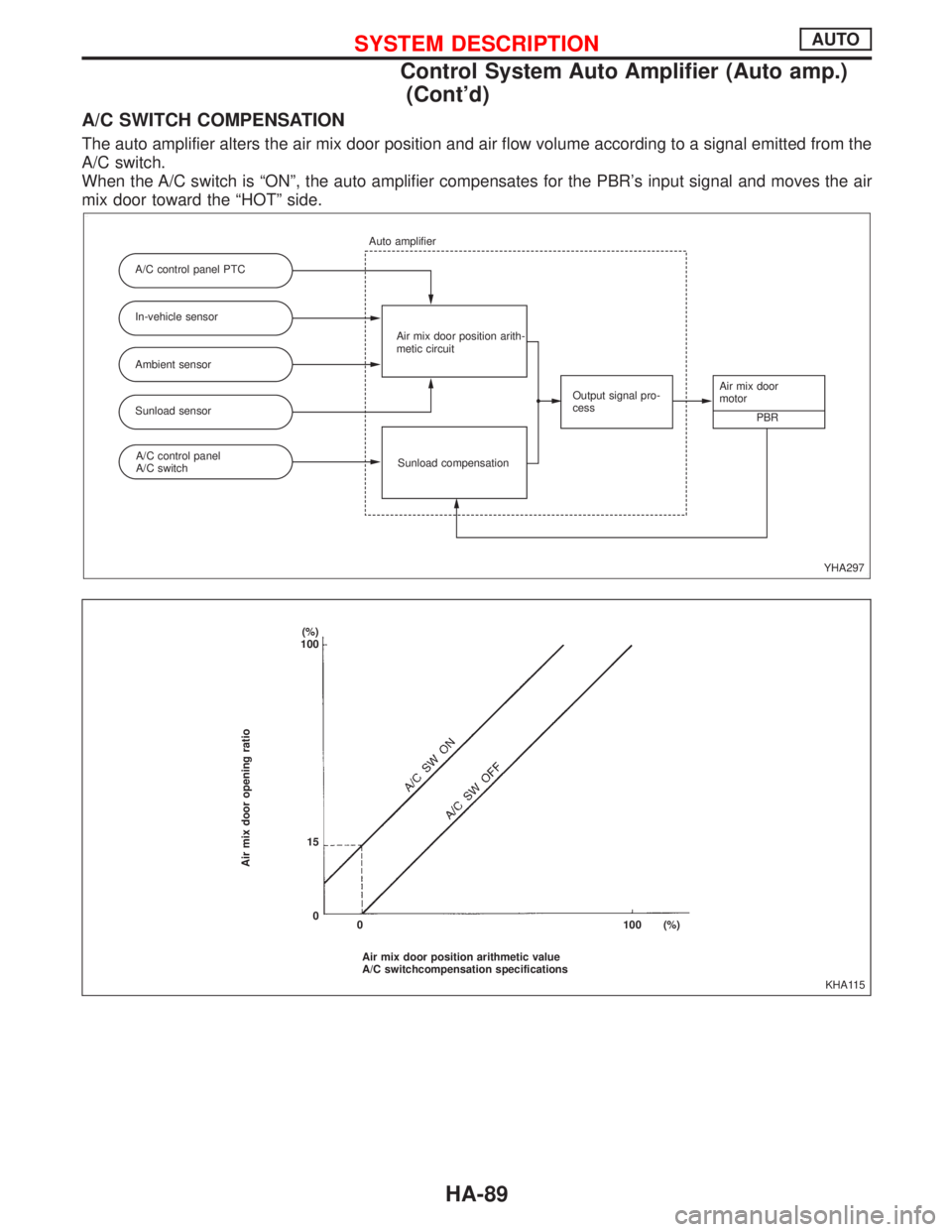
A/C SWITCH COMPENSATION
The auto amplifier alters the air mix door position and air flow volume according to a signal emitted from the
A/C switch.
When the A/C switch is ªONº, the auto amplifier compensates for the PBR's input signal and moves the air
mix door toward the ªHOTº side.
YHA297 A/C control panel PTC
In-vehicle sensor
Ambient sensor
Sunload sensor
Sunload compensation Auto amplifier
Air mix door position arith-
metic circuit
Output signal pro-
cessAir mix door
motor
PBR
A/C control panel
A/C switch
KHA115
Air mix door opening ratio
(%)
100
15
0
Air mix door position arithmetic value
A/C switchcompensation specifications 0 100 (%)
SYSTEM DESCRIPTIONAUTO
Control System Auto Amplifier (Auto amp.)
(Cont'd)
HA-89
Page 1939 of 2267
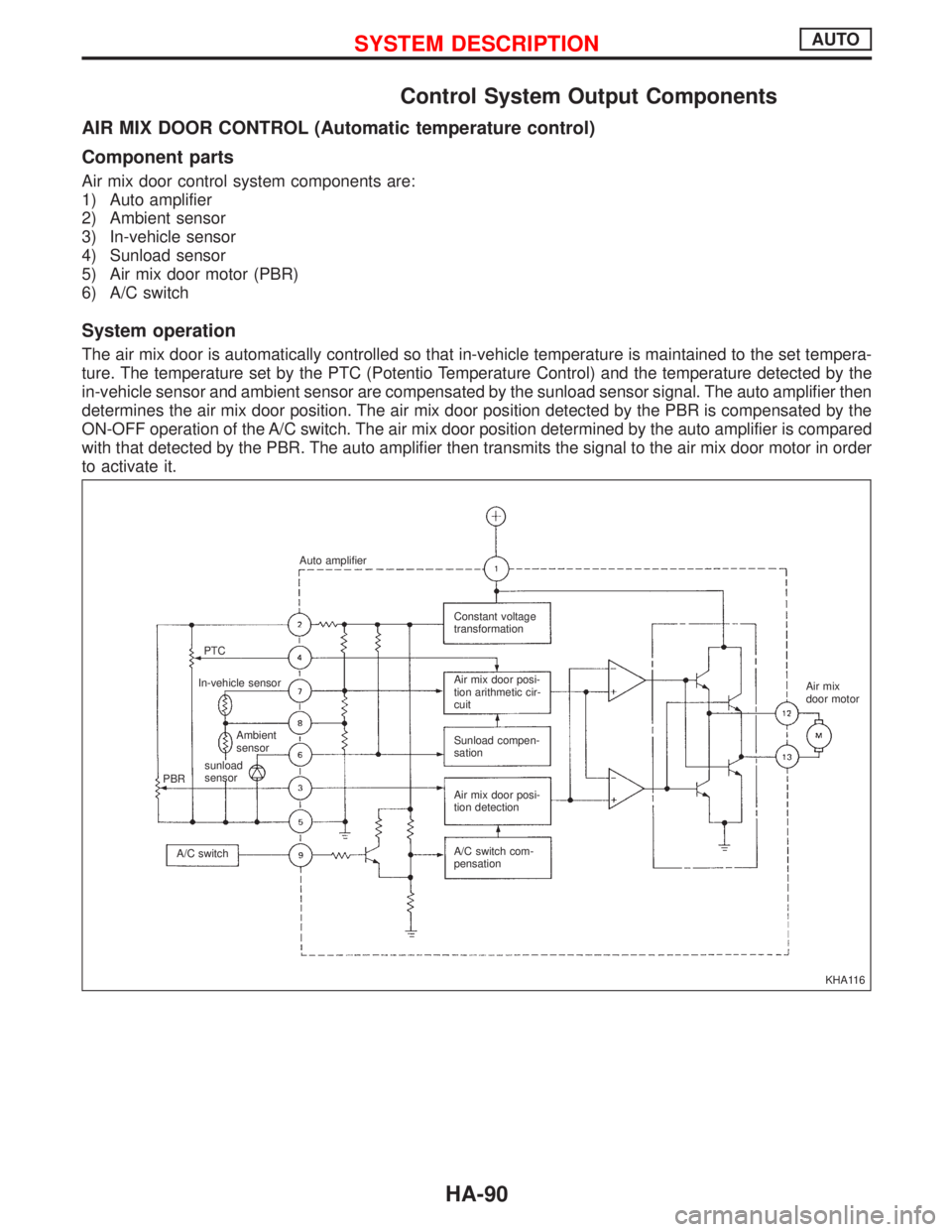
Control System Output Components
AIR MIX DOOR CONTROL (Automatic temperature control)
Component parts
Air mix door control system components are:
1) Auto amplifier
2) Ambient sensor
3) In-vehicle sensor
4) Sunload sensor
5) Air mix door motor (PBR)
6) A/C switch
System operation
The air mix door is automatically controlled so that in-vehicle temperature is maintained to the set tempera-
ture. The temperature set by the PTC (Potentio Temperature Control) and the temperature detected by the
in-vehicle sensor and ambient sensor are compensated by the sunload sensor signal. The auto amplifier then
determines the air mix door position. The air mix door position detected by the PBR is compensated by the
ON-OFF operation of the A/C switch. The air mix door position determined by the auto amplifier is compared
with that detected by the PBR. The auto amplifier then transmits the signal to the air mix door motor in order
to activate it.
KHA116 Auto amplifier
PTC
In-vehicle sensor
Ambient
sensor
sunload
sensor
PBR
A/C switchConstant voltage
transformation
Air mix door posi-
tion arithmetic cir-
cuit
Sunload compen-
sation
Air mix door posi-
tion detection
A/C switch com-
pensationAir mix
door motor
SYSTEM DESCRIPTIONAUTO
HA-90
Page 1940 of 2267
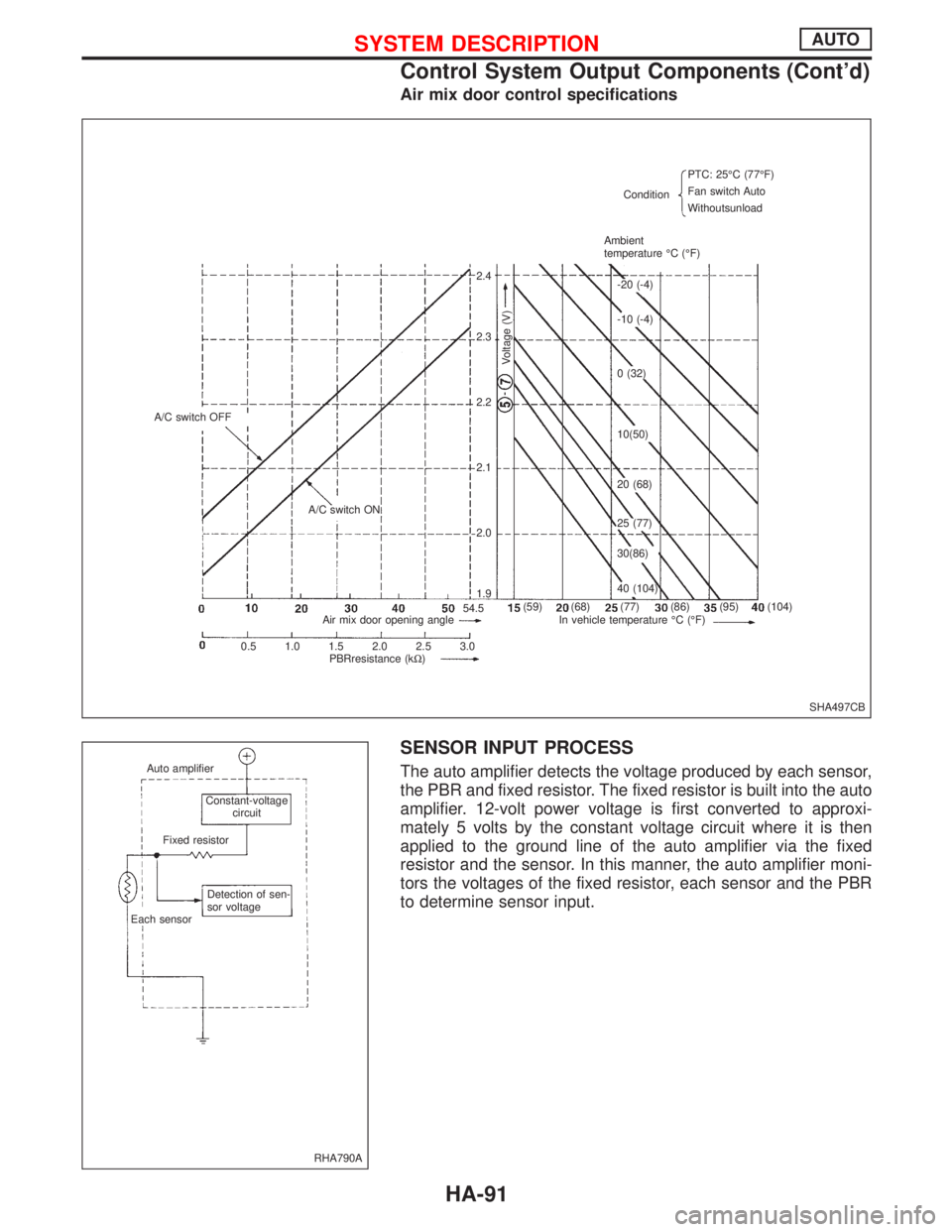
Air mix door control specifications
SENSOR INPUT PROCESS
The auto amplifier detects the voltage produced by each sensor,
the PBR and fixed resistor. The fixed resistor is built into the auto
amplifier. 12-volt power voltage is first converted to approxi-
mately 5 volts by the constant voltage circuit where it is then
applied to the ground line of the auto amplifier via the fixed
resistor and the sensor. In this manner, the auto amplifier moni-
tors the voltages of the fixed resistor, each sensor and the PBR
to determine sensor input.
SHA497CB A/C switch OFF
A/C switch ON
Voltage (V)
ConditionPTC: 25ÉC (77ÉF)
Fan switch Auto
Withoutsunload
Ambient
temperature ÉC (ÉF)
Air mix door opening angle In vehicle temperature ÉC (ÉF)
0.5 1.0 1.5 2.0 2.5 3.0
PBRresistance (kW)2.4
2.3
2.2
2.1
2.0
1.9
(59) (68) (77) (86) (95) (104)-20 (-4)
-10 (-4)
0 (32)
10(50)
20 (68)
25 (77)
30(86)
40 (104)
54.5
RHA790A Auto amplifier
Constant-voltage
circuit
Fixed resistor
Detection of sen-
sor voltage
Each sensor
SYSTEM DESCRIPTIONAUTO
Control System Output Components (Cont'd)
HA-91