NISSAN PRIMERA 1999 Electronic Repair Manual
Manufacturer: NISSAN, Model Year: 1999, Model line: PRIMERA, Model: NISSAN PRIMERA 1999Pages: 2267, PDF Size: 35.74 MB
Page 1941 of 2267
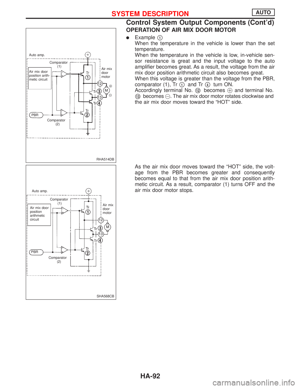
OPERATION OF AIR MIX DOOR MOTOR
lExamplep1
When the temperature in the vehicle is lower than the set
temperature.
When the temperature in the vehicle is low, in-vehicle sen-
sor resistance is great and the input voltage to the auto
amplifier becomes great. As a result, the voltage from the air
mix door position arithmetic circuit also becomes great.
When this voltage is greater than the voltage from the PBR,
comparator (1), Tr
p1and Trp4turn ON.
Accordingly terminal No.
p12becomes!and terminal No.
p13becomes@. The air mix door motor rotates clockwise and
the air mix door moves toward the ªHOTº side.
As the air mix door moves toward the ªHOTº side, the volt-
age from the PBR becomes greater and consequently
becomes equal to that from the air mix door position arith-
metic circuit. As a result, comparator (1) turns OFF and the
air mix door motor stops.
RHA514DB Auto amp.
Comparator
(1)
Air mix door
position arith-
metic circuitAir mix
door
motor
PBR
Comparator
(2)
SHA568CB Auto amp.
Comparator
(1)
Air mix door
position
arithmetic
circuit
PBR
Comparator
(2)Air mix
door
motor
SYSTEM DESCRIPTIONAUTO
Control System Output Components (Cont'd)
HA-92
Page 1942 of 2267
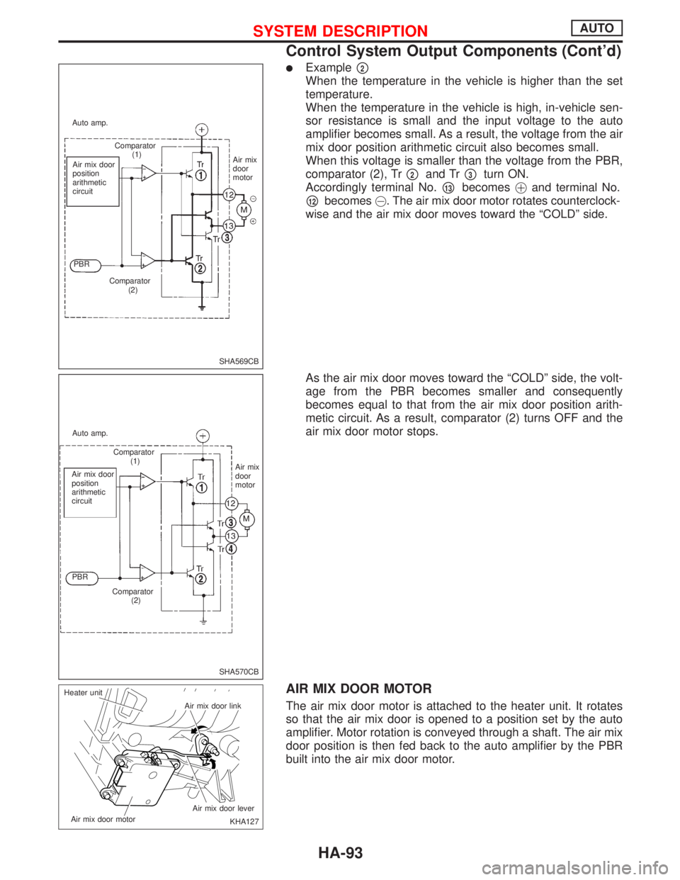
lExamplep2
When the temperature in the vehicle is higher than the set
temperature.
When the temperature in the vehicle is high, in-vehicle sen-
sor resistance is small and the input voltage to the auto
amplifier becomes small. As a result, the voltage from the air
mix door position arithmetic circuit also becomes small.
When this voltage is smaller than the voltage from the PBR,
comparator (2), Tr
p2and Trp3turn ON.
Accordingly terminal No.
p13becomes!and terminal No.
p12becomes@. The air mix door motor rotates counterclock-
wise and the air mix door moves toward the ªCOLDº side.
As the air mix door moves toward the ªCOLDº side, the volt-
age from the PBR becomes smaller and consequently
becomes equal to that from the air mix door position arith-
metic circuit. As a result, comparator (2) turns OFF and the
air mix door motor stops.
AIR MIX DOOR MOTOR
The air mix door motor is attached to the heater unit. It rotates
so that the air mix door is opened to a position set by the auto
amplifier. Motor rotation is conveyed through a shaft. The air mix
door position is then fed back to the auto amplifier by the PBR
built into the air mix door motor.
SHA569CB Auto amp.
Comparator
(1)
Air mix door
position
arithmetic
circuit
PBR
Comparator
(2)Air mix
door
motor
SHA570CB Auto amp.
Comparator
(1)
Air mix door
position
arithmetic
circuit
PBR
Comparator
(2)Air mix
door
motor
KHA127 Air mix door link
Air mix door lever
Air mix door motor Heater unit
SYSTEM DESCRIPTIONAUTO
Control System Output Components (Cont'd)
HA-93
Page 1943 of 2267
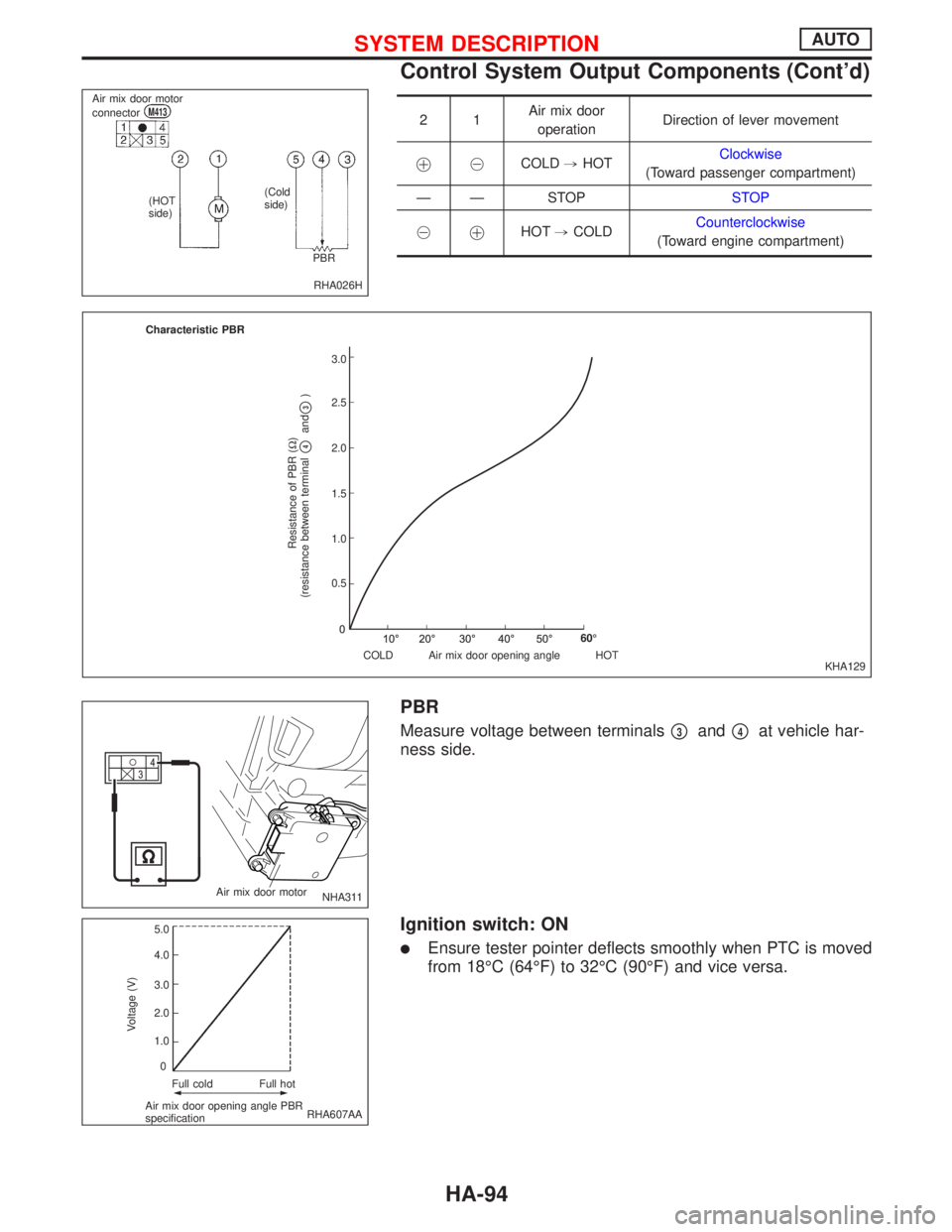
21Air mix door
operationDirection of lever movement
!@COLD,HOTClockwise
(Toward passenger compartment)
Ð Ð STOPSTOP
@
!HOT,COLDCounterclockwise
(Toward engine compartment)
PBR
Measure voltage between terminalsp3andp4at vehicle har-
ness side.
Ignition switch: ON
lEnsure tester pointer deflects smoothly when PTC is moved
from 18ÉC (64ÉF) to 32ÉC (90ÉF) and vice versa.
RHA026H Air mix door motor
connector
M413
(HOT
side)(Cold
side)
PBR
KHA129 Characteristic PBR
Resistance of PBR (W)
(resistance between terminal
p4and
p3)
.3.0
2.5
2.0
1.5
1.0
0.5
COLD Air mix door opening angle HOT60É
NHA311 Air mix door motor
RHA607AA
Voltage (V)
Full cold Full hot
Air mix door opening angle PBR
specification5.0
4.0
3.0
2.0
1.0
0
SYSTEM DESCRIPTIONAUTO
Control System Output Components (Cont'd)
HA-94
Page 1944 of 2267
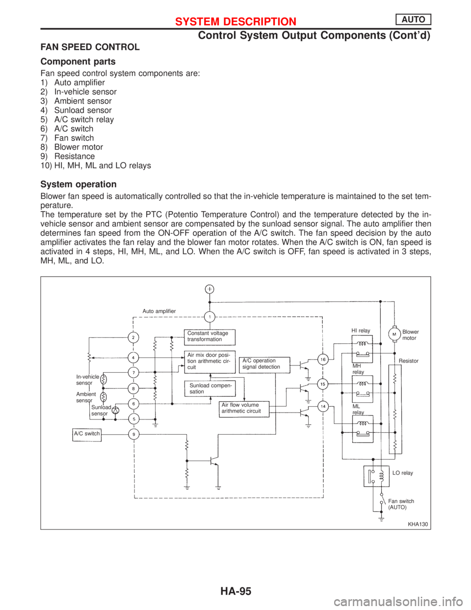
FAN SPEED CONTROL
Component parts
Fan speed control system components are:
1) Auto amplifier
2) In-vehicle sensor
3) Ambient sensor
4) Sunload sensor
5) A/C switch relay
6) A/C switch
7) Fan switch
8) Blower motor
9) Resistance
10) HI, MH, ML and LO relays
System operation
Blower fan speed is automatically controlled so that the in-vehicle temperature is maintained to the set tem-
perature.
The temperature set by the PTC (Potentio Temperature Control) and the temperature detected by the in-
vehicle sensor and ambient sensor are compensated by the sunload sensor signal. The auto amplifier then
determines fan speed from the ON-OFF operation of the A/C switch. The fan speed decision by the auto
amplifier activates the fan relay and the blower fan motor rotates. When the A/C switch is ON, fan speed is
activated in 4 steps, HI, MH, ML, and LO. When the A/C switch is OFF, fan speed is activated in 3 steps,
MH, ML, and LO.
KHA130 Auto amplifier
In-vehicle
sensor
Ambient
sensor
Sunload
sensor
A/C switchConstant voltage
transformation
Air mix door posi-
tion arithmetic cir-
cuit
Sunload compen-
sationA/C operation
signal detection
Air flow volume
arithmetic circuitHI relay
MH
relay
ML
relayBlower
motor
Resistor
LO relay
Fan switch
(AUTO)
SYSTEM DESCRIPTIONAUTO
Control System Output Components (Cont'd)
HA-95
Page 1945 of 2267
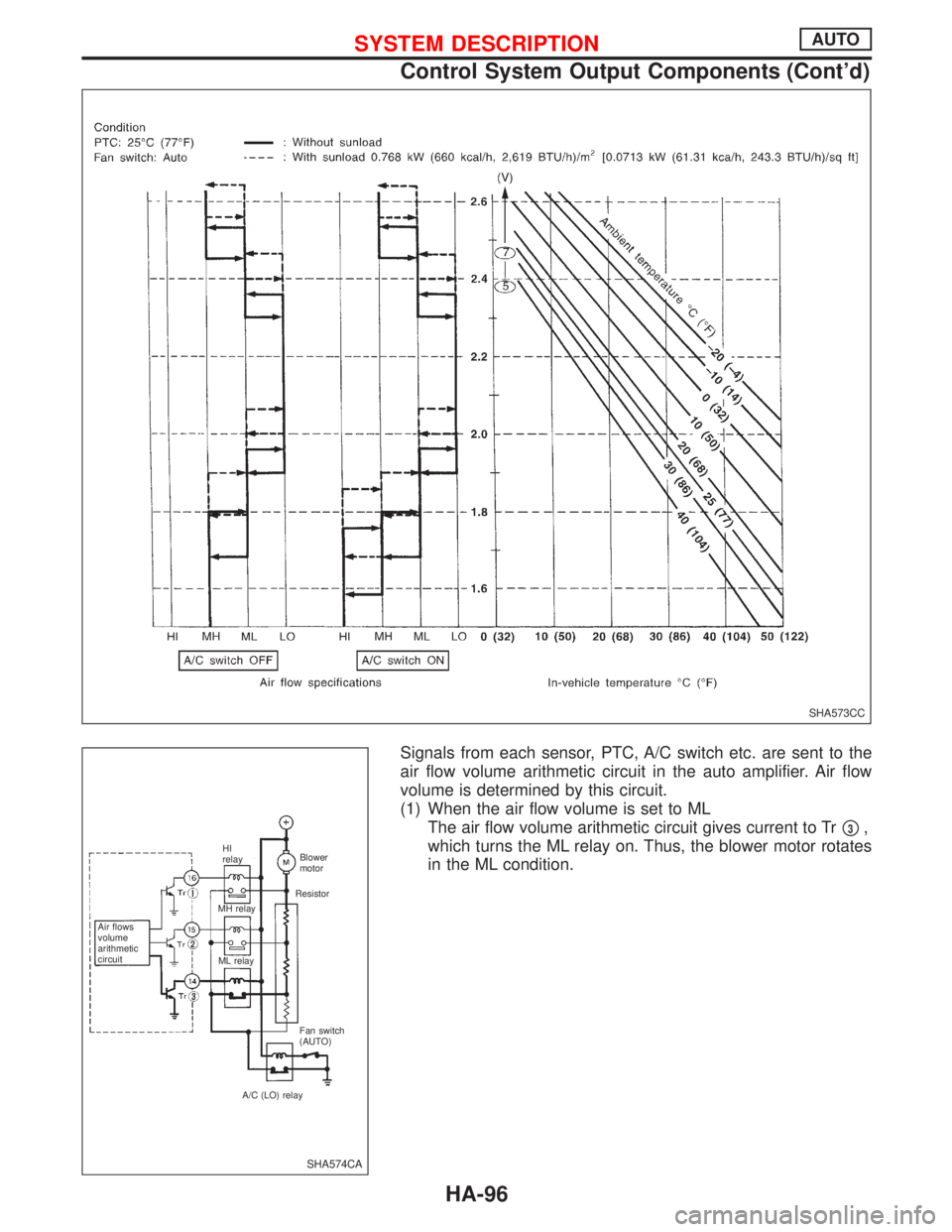
Signals from each sensor, PTC, A/C switch etc. are sent to the
air flow volume arithmetic circuit in the auto amplifier. Air flow
volume is determined by this circuit.
(1) When the air flow volume is set to ML
The air flow volume arithmetic circuit gives current to Tr
p3,
which turns the ML relay on. Thus, the blower motor rotates
in the ML condition.
SHA573CC
SHA574CA
Air flows
volume
arithmetic
circuitHI
relay
MH relay
ML relayBlower
motor
Resistor
Fan switch
(AUTO)
A/C (LO) relay
SYSTEM DESCRIPTIONAUTO
Control System Output Components (Cont'd)
HA-96
Page 1946 of 2267
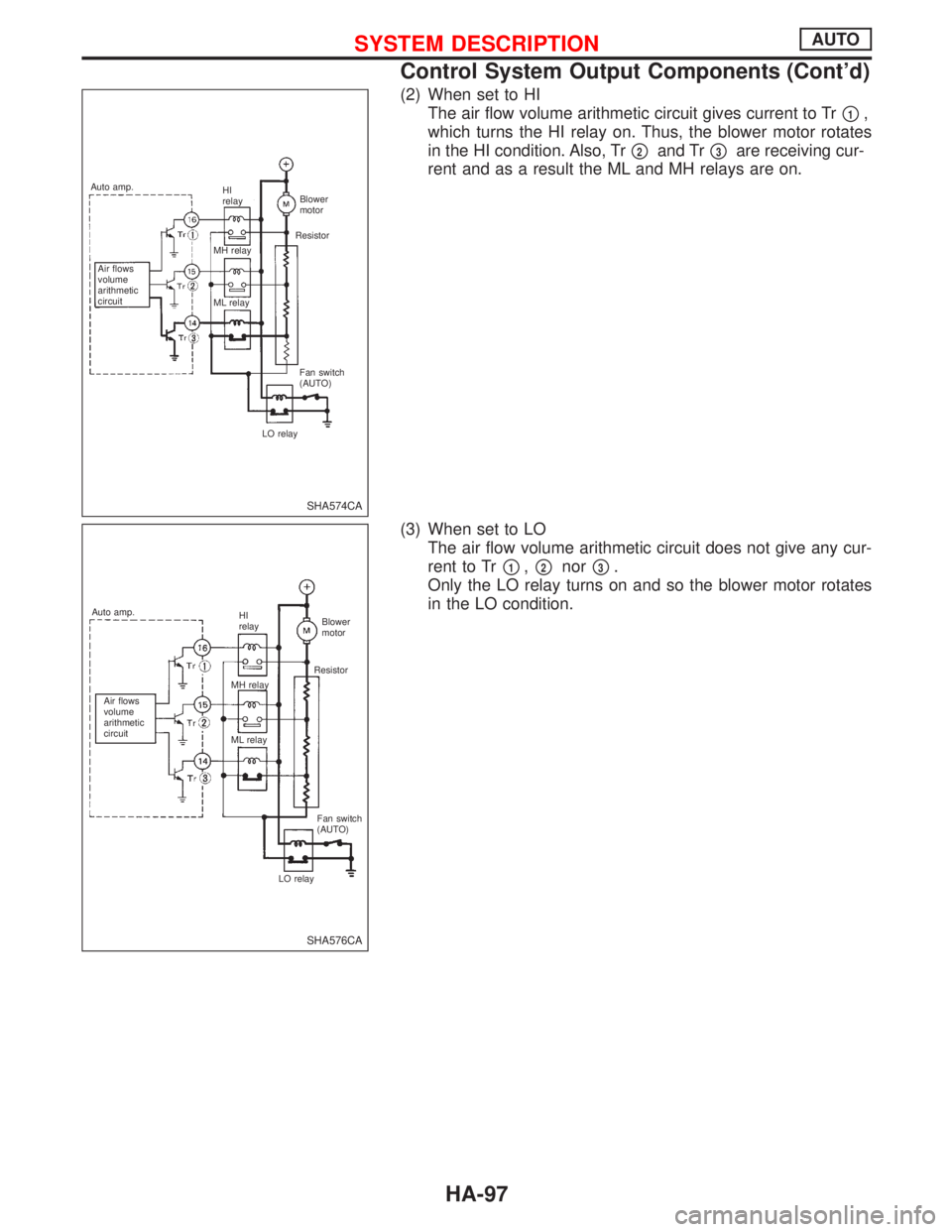
(2) When set to HI
The air flow volume arithmetic circuit gives current to Tr
p1,
which turns the HI relay on. Thus, the blower motor rotates
in the HI condition. Also, Tr
p2and Trp3are receiving cur-
rent and as a result the ML and MH relays are on.
(3) When set to LO
The air flow volume arithmetic circuit does not give any cur-
rent to Tr
p1,p2norp3.
Only the LO relay turns on and so the blower motor rotates
in the LO condition.
SHA574CA
Air flows
volume
arithmetic
circuitHI
relay
MH relay
ML relayBlower
motor
Resistor
Fan switch
(AUTO)
LO relay Auto amp.
SHA576CA
Air flows
volume
arithmetic
circuitHI
relay
MH relay
ML relayBlower
motor
Resistor
Fan switch
(AUTO)
LO relay Auto amp.
SYSTEM DESCRIPTIONAUTO
Control System Output Components (Cont'd)
HA-97
Page 1947 of 2267
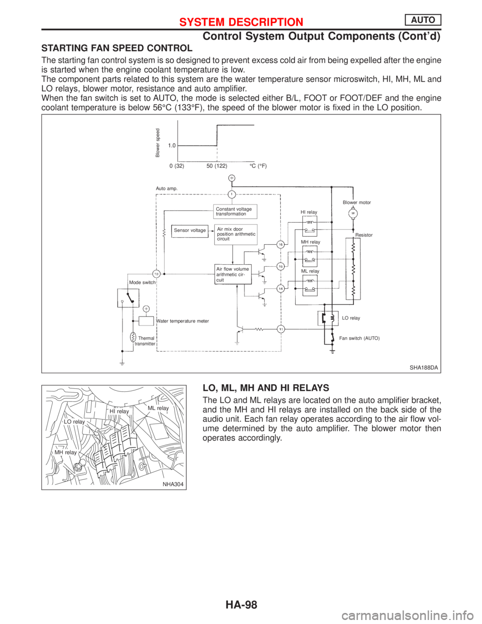
STARTING FAN SPEED CONTROL
The starting fan control system is so designed to prevent excess cold air from being expelled after the engine
is started when the engine coolant temperature is low.
The component parts related to this system are the water temperature sensor microswitch, HI, MH, ML and
LO relays, blower motor, resistance and auto amplifier.
When the fan switch is set to AUTO, the mode is selected either B/L, FOOT or FOOT/DEF and the engine
coolant temperature is below 56ÉC (133ÉF), the speed of the blower motor is fixed in the LO position.
LO, ML, MH AND HI RELAYS
The LO and ML relays are located on the auto amplifier bracket,
and the MH and HI relays are installed on the back side of the
audio unit. Each fan relay operates according to the air flow vol-
ume determined by the auto amplifier. The blower motor then
operates accordingly.
SHA188DA
Blower speed
1.0
0 (32) 50 (122) ÉC (ÉF)
Auto amp.
.Constant voltage
transformation
Sensor voltage
.Air mix door
position arithmetic
circuit
Air flow volume
arithmetic cir-
cuit
Mode switch
Water temperature meter
Thermal
transmitterFan switch (AUTO)LO relay ML relay MH relay HI relay
.Blower motor
Resistor
NHA304
.LO relay
.ML relay.HI relay
.MH relay
SYSTEM DESCRIPTIONAUTO
Control System Output Components (Cont'd)
HA-98
Page 1948 of 2267
SHA578CA Auto amplifier
Air flows volume arith-
metic circuitHI relay
MH relay
ML relay
LO relay
Fan switch (AUTO)IGN ACC
Resistor
SYSTEM DESCRIPTIONAUTO
Control System Output Components (Cont'd)
HA-99
Page 1949 of 2267
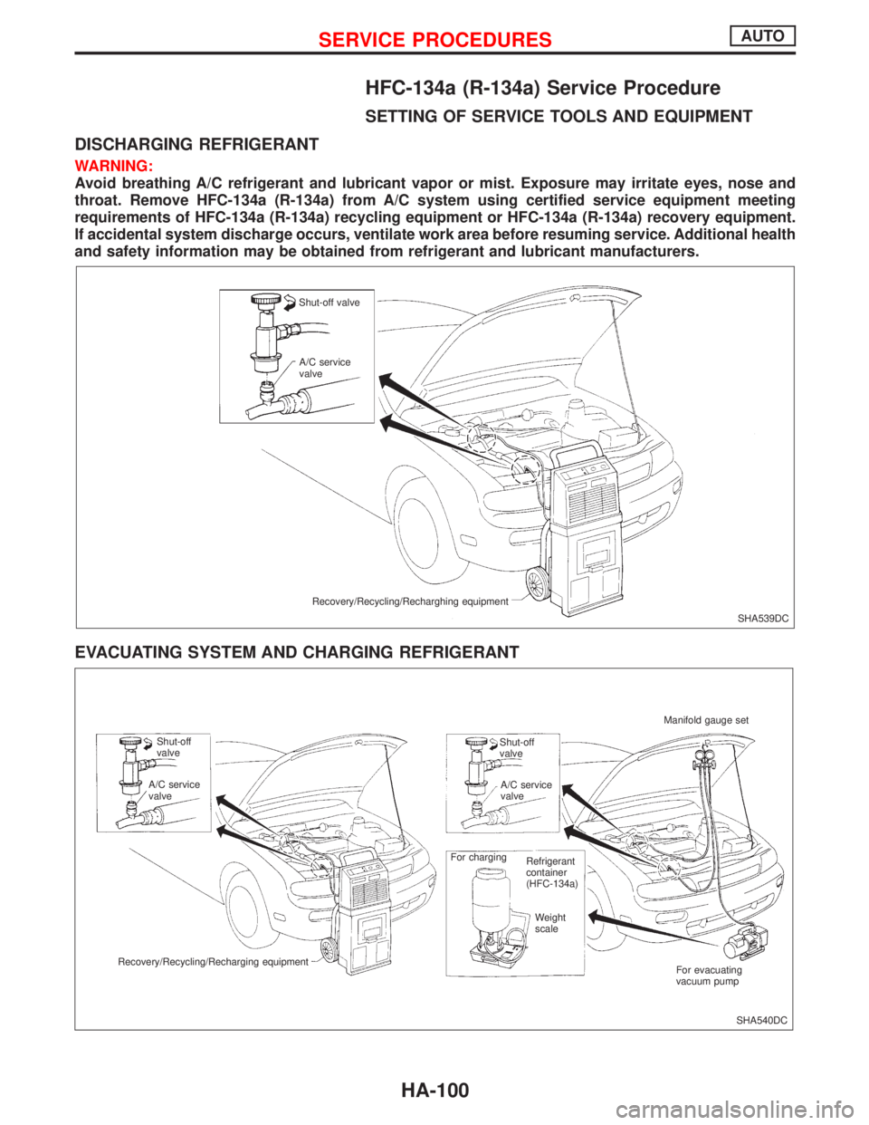
HFC-134a (R-134a) Service Procedure
SETTING OF SERVICE TOOLS AND EQUIPMENT
DISCHARGING REFRIGERANT
WARNING:
Avoid breathing A/C refrigerant and lubricant vapor or mist. Exposure may irritate eyes, nose and
throat. Remove HFC-134a (R-134a) from A/C system using certified service equipment meeting
requirements of HFC-134a (R-134a) recycling equipment or HFC-134a (R-134a) recovery equipment.
If accidental system discharge occurs, ventilate work area before resuming service. Additional health
and safety information may be obtained from refrigerant and lubricant manufacturers.
EVACUATING SYSTEM AND CHARGING REFRIGERANT
SHA539DC Shut-off valve
A/C service
valve
Recovery/Recycling/Recharghing equipment
SHA540DC Shut-off
valve
A/C service
valve
Recovery/Recycling/Recharging equipmentShut-off
valve
A/C service
valve
For charging
Refrigerant
container
(HFC-134a)
Weight
scale
For evacuating
vacuum pump Manifold gauge set
SERVICE PROCEDURESAUTO
HA-100
Page 1950 of 2267
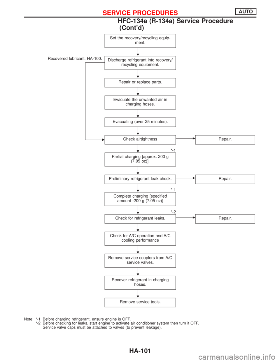
Recovered lubricant. HA-100.Set the recovery/recycling equip-
ment.Discharge refrigerant into recovery/
recycling equipment.
Repair or replace parts.
Evacuate the unwanted air in
charging hoses.
Evacuating (over 25 minutes).
ECheck airtightness
*-1
ERepair.
Partial charging [approx. 200 g
(7.05 oz)].
Preliminary refrigerant leak check.
*-1
ERepair.
Complete charging [specified
amount -200 g (7.05 oz)]
*-2
Check for refrigerant leaks.
ERepair.
Check for A/C operation and A/C
cooling performance
Remove service couplers from A/C
service valves.
Recover refrigerant in charging
hoses.
Remove service tools.
Note: *-1 Before charging refrigerant, ensure engine is OFF.
*-2 Before checking for leaks, start engine to activate air conditioner system then turn it OFF.
Service valve caps must be attached to valves (to prevent leakage).
H
H
H
H
H
H
H
H
H
H
H
H
H
SERVICE PROCEDURESAUTO
HFC-134a (R-134a) Service Procedure
(Cont'd)
HA-101