Supplemental Restraint System (SRS) ªAIR
BAGº and ªSEAT BELT PRE-TENSIONERº
NCEC0002The Supplemental Restraint System ªAIR BAGº and ªSEAT BELT PRE-TENSIONERº, used along with a seat
belt, help to reduce the risk or severity of injury to the driver and front passenger in a frontal collision. The
Supplemental Restraint System consists of air bag modules (located in the center of the steering wheel and
on the instrument panel on the passenger side), seat belt pre-tensioners, a diagnosis sensor unit, warning
lamp, wiring harness and spiral cable.
In addition to the supplemental air bag modules for a frontal collision, the supplemental side air bag used along
with the seat belt helps to reduce the risk or severity of injury to the driver and front passenger in a side col-
lision. The supplemental side air bag consists of air bag modules (located in the outer side of front seats),
satellite sensor, diagnosis sensor unit (one of components of supplemental air bags for a frontal collision),
wiring harness, warning lamp (one of components of supplemental air bags for a frontal collision). Information
necessary to service the system safely is included in theRS sectionof this Service Manual.
WARNING:
ITo avoid rendering the SRS inoperative, which could increase the risk of personal injury or death
in the event of a collision which would result in air bag inflation, all maintenance must be performed
by an authorized NISSAN dealer.
IImproper maintenance, including incorrect removal and installation of the SRS, can lead to per-
sonal injury caused by unintentional activation of the system.
IDo not use electrical test equipment on any circuit related to the SRS unless instructed to in this
Service Manual. SRS wiring harnesses (except ªSEAT BELT PRE-TENSIONERº connector) can be
identified with yellow harness connector (and with yellow harness protector or yellow insulation
tape before the harness connectors).
Precautions for On Board Diagnostic (OBD)
System of Engine
NCEC0003The ECM has an on board diagnostic system. It will light up the malfunction indicator (MI) to warn the driver
of a malfunction causing emission deterioration.
CAUTION:
IBe sure to turn the ignition switch ªOFFº and disconnect the negative battery terminal before any
repair or inspection work. The open/short circuit of related switches, sensors, solenoid valves, etc.
will cause the MI to light up.
IBe sure to connect and lock the connectors securely after work. A loose (unlocked) connector will
cause the MI to light up due to the open circuit. (Be sure the connector is free from water, grease,
dirt, bent terminals, etc.)
ICertain systems and components, especially those related to OBD, may use a new style slide-
locking type harness connector.
For description and how to disconnect, refer to EL section, ªDescriptionº, ªHARNESS CONNEC-
TORº.
IBe sure to route and secure the harnesses properly after work. The interference of the harness with
a bracket, etc. may cause the MI to light up due to the short circuit.
IBe sure to connect rubber tubes properly after work. A misconnected or disconnected rubber tube
may cause the MI to light up due to the malfunction of the EGR system or fuel injection system,
etc.
IBe sure to erase the unnecessary malfunction information (repairs completed) from the ECM before
returning the vehicle to the customer.
PRECAUTIONSQG16I18DE
Supplemental Restraint System (SRS) ªAIR BAGº and ªSEAT BELT PRE-TENSIONERº
EC-9
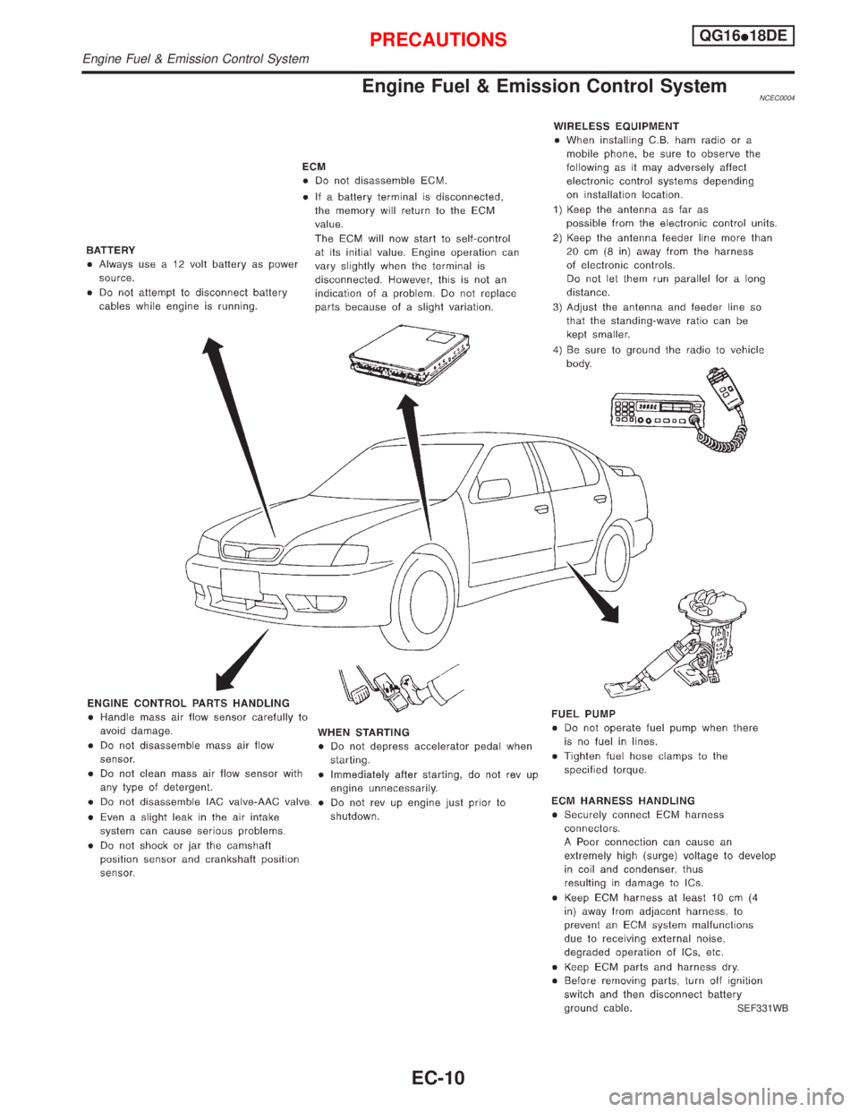
PrecautionsNCEC0005IBefore connecting or disconnecting the ECM harness
connector, turn ignition switch OFF and disconnect nega-
tive battery terminal. Failure to do so may damage the
ECM because battery voltage is applied to ECM even if
ignition switch is turned off.
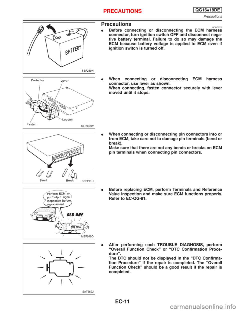
IWhen connecting or disconnecting ECM harness
connector, use lever as shown.
When connecting, fasten connector securely with lever
moved until it stops.
IWhen connecting or disconnecting pin connectors into or
from ECM, take care not to damage pin terminals (bend or
break).
Make sure that there are not any bends or breaks on ECM
pin terminals when connecting pin connectors.
IBefore replacing ECM, perform Terminals and Reference
Value inspection and make sure ECM functions properly.
Refer to EC-QG-91.
IAfter performing each TROUBLE DIAGNOSIS, perform
ªOverall Function Checkº or ªDTC Confirmation Proce-
dureº.
The DTC should not be displayed in the ªDTC Confirma-
tion Procedureº if the repair is completed. The ªOverall
Function Checkº should be a good result if the repair is
completed.
SEF289H
SEF908W
SEF291H
MEF040D
SAT652J
PRECAUTIONSQG16I18DE
Precautions
EC-11
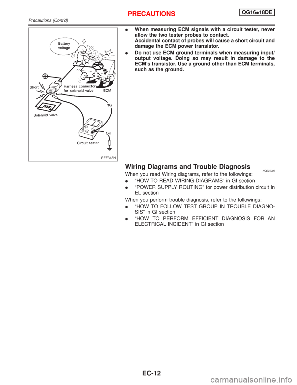
IWhen measuring ECM signals with a circuit tester, never
allow the two tester probes to contact.
Accidental contact of probes will cause a short circuit and
damage the ECM power transistor.
IDo not use ECM ground terminals when measuring input/
output voltage. Doing so may result in damage to the
ECM's transistor. Use a ground other than ECM terminals,
such as the ground.
Wiring Diagrams and Trouble DiagnosisNCEC0006When you read Wiring diagrams, refer to the followings:
IªHOW TO READ WIRING DIAGRAMSº in GI section
IªPOWER SUPPLY ROUTINGº for power distribution circuit in
EL section
When you perform trouble diagnosis, refer to the followings:
IªHOW TO FOLLOW TEST GROUP IN TROUBLE DIAGNO-
SISº in GI section
IªHOW TO PERFORM EFFICIENT DIAGNOSIS FOR AN
ELECTRICAL INCIDENTº in GI section
SEF348N
PRECAUTIONSQG16I18DE
Precautions (Cont'd)
EC-12
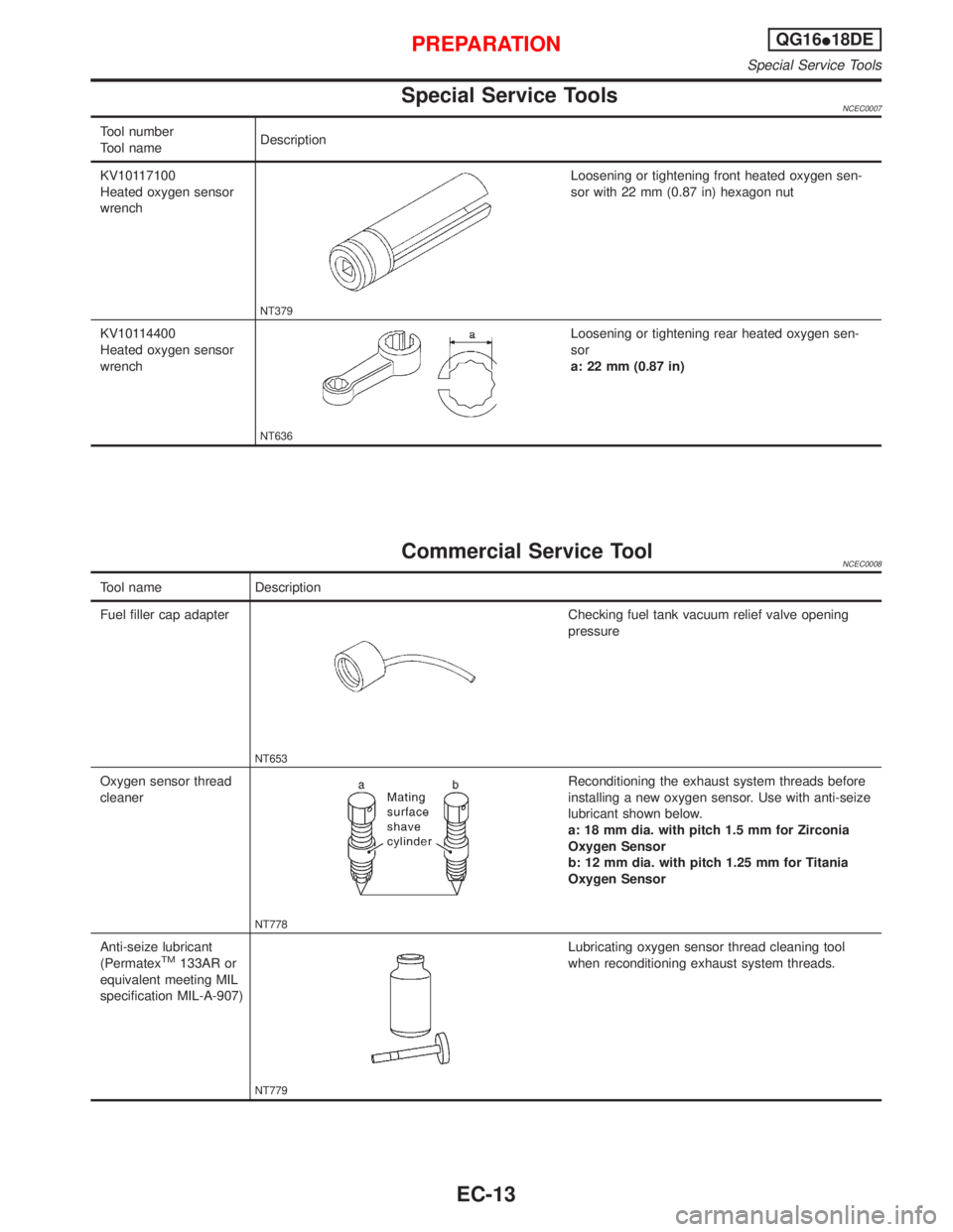
Special Service ToolsNCEC0007
Tool number
Tool nameDescription
KV10117100
Heated oxygen sensor
wrench
NT379
Loosening or tightening front heated oxygen sen-
sor with 22 mm (0.87 in) hexagon nut
KV10114400
Heated oxygen sensor
wrench
NT636
Loosening or tightening rear heated oxygen sen-
sor
a: 22 mm (0.87 in)
Commercial Service ToolNCEC0008
Tool name Description
Fuel filler cap adapter
NT653
Checking fuel tank vacuum relief valve opening
pressure
Oxygen sensor thread
cleaner
NT778
Reconditioning the exhaust system threads before
installing a new oxygen sensor. Use with anti-seize
lubricant shown below.
a: 18 mm dia. with pitch 1.5 mm for Zirconia
Oxygen Sensor
b: 12 mm dia. with pitch 1.25 mm for Titania
Oxygen Sensor
Anti-seize lubricant
(Permatex
TM133AR or
equivalent meeting MIL
specification MIL-A-907)
NT779
Lubricating oxygen sensor thread cleaning tool
when reconditioning exhaust system threads.
PREPARATIONQG16I18DE
Special Service Tools
EC-13
