NISSAN PRIMERA 1999 Electronic Repair Manual
Manufacturer: NISSAN, Model Year: 1999, Model line: PRIMERA, Model: NISSAN PRIMERA 1999Pages: 2267, PDF Size: 35.74 MB
Page 481 of 2267
Together with the DTC, the SRT code is cleared from the ECM memory using the method described later
(Refer to EC-QG-44). In addition, after engine control components/system are repaired or if the battery termi-
nals remain disconnected for more than 24 hours, all SRT codes may be cleared from the ECM memory.
How to Display SRT CodeNCEC0031S03011.With CONSULT-II
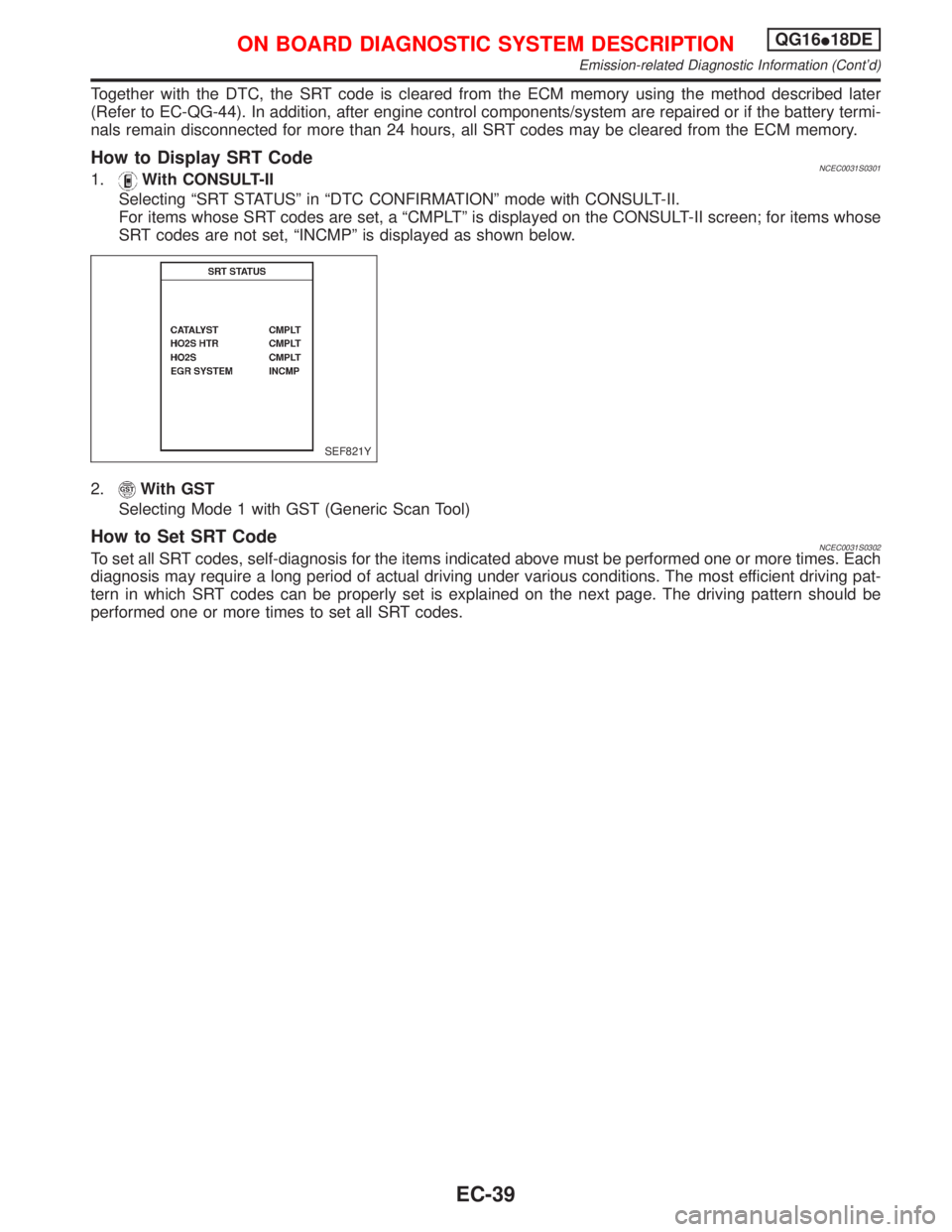
Selecting ªSRT STATUSº in ªDTC CONFIRMATIONº mode with CONSULT-II.
For items whose SRT codes are set, a ªCMPLTº is displayed on the CONSULT-II screen; for items whose
SRT codes are not set, ªINCMPº is displayed as shown below.
2.
With GST
Selecting Mode 1 with GST (Generic Scan Tool)
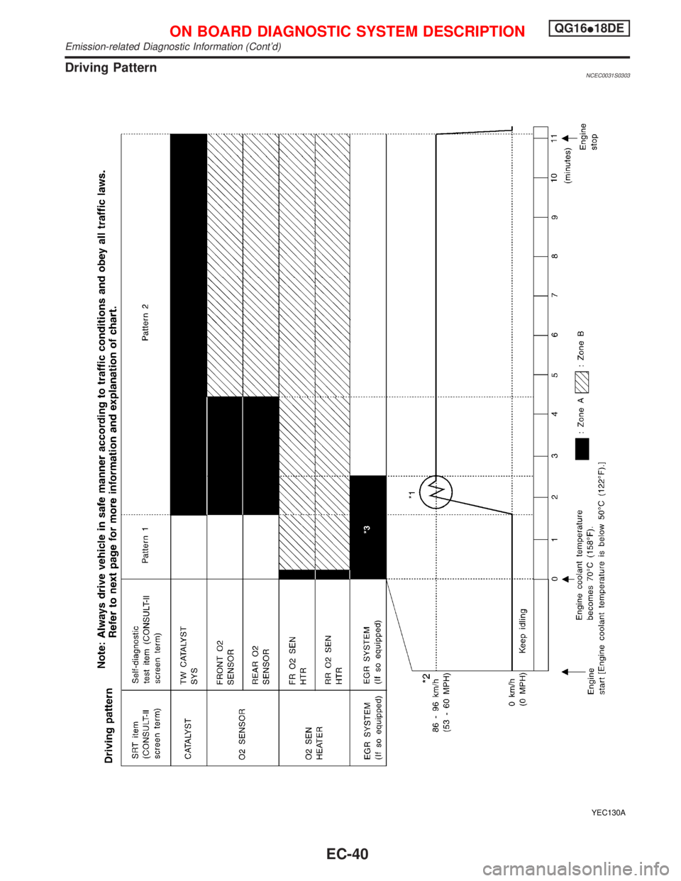
How to Set SRT CodeNCEC0031S0302To set all SRT codes, self-diagnosis for the items indicated above must be performed one or more times. Each
diagnosis may require a long period of actual driving under various conditions. The most efficient driving pat-
tern in which SRT codes can be properly set is explained on the next page. The driving pattern should be
performed one or more times to set all SRT codes.
SEF821Y
ON BOARD DIAGNOSTIC SYSTEM DESCRIPTIONQG16I18DE
Emission-related Diagnostic Information (Cont'd)
EC-39
Page 482 of 2267
Driving PatternNCEC0031S0303
YEC130A
ON BOARD DIAGNOSTIC SYSTEM DESCRIPTIONQG16I18DE
Emission-related Diagnostic Information (Cont'd)
EC-40
Page 483 of 2267
IThe time required for each diagnosis varies with road surface conditions, weather, altitude, individual driv-
ing habits, etc.
Zone A refers to the range where the time required, for the diagnosis under normal conditions*, is the
shortest. Zone B refers to the range where the diagnosis can still be performed if the diagnosis is not
completed within zone A.
*: Normal conditions refer to the following:
þ Sea level
þ Flat road
þ Ambient air temperature: 20 - 30ÉC (68 - 86ÉF)
þ Diagnosis is performed as quickly as possible under normal conditions.
Under different conditions [For example: ambient air temperature other than 20 - 30ÉC (68 - 86ÉF)], diagnosis may
also be performed.
Pattern 1:
IThe engine is started at the engine coolant temperature of þ10 to 35ÉC (14 to 95ÉF) (where the volt-
age between the ECM terminals 70 and 58 is 3.0 - 4.3V).
IThe engine must be operated at idle speed until the engine coolant temperature is greater than 70ÉC
(158ÉF) (where the voltage between the ECM terminals 70 and 58 is lower than 1.4V).
Pattern 2:
IWhen steady-state driving is performed again even after it is interrupted, each diagnosis can be conducted.
In this case, the time required for diagnosis may be extended.
*1: Depress the accelerator pedal until vehicle speed is 90 km/h (56 MPH), then release the accelerator pedal
and keep it released for more than 10 seconds. Depress the accelerator pedal until vehicle speed is 90
km/h (56 MPH) again.
*2: Checking the vehicle speed with CONSULT-II or GST is advised.
*3: The driving pattern may be omitted when all the followings are performed using the ªDTC WORK SUP-
PORTº mode with CONSULT-II.
IªEGR SYSTEM P0400º (If so equipped)
IªEGR SYSTEM P1402º (If so equipped)
Suggested upshift speeds
Shown below are suggested vehicle speeds for shifting into a higher gear. These suggestions relate to fuel
economy and vehicle performance. Actual upshift speeds will vary according to road conditions, the weather
and individual driving habits.
Gear changeACCEL shift point
km/h (MPH)
1st to 2nd 15 (9)
2nd to 3rd 35 (22)
3rd to 4th 50 (31)
4th to 5th 70 (43)
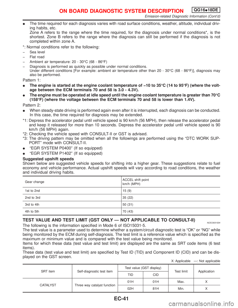
TEST VALUE AND TEST LIMIT (GST ONLY Ð NOT APPLICABLE TO CONSULT-II)NCEC0031S04The following is the information specified in Mode 6 of ISO15031-5.
The test value is a parameter used to determine whether a system/circuit diagnostic test is ªOKº or ªNGº while
being monitored by the ECM during self-diagnosis. The test limit is a reference value which is specified as the
maximum or minimum value and is compared with the test value being monitored.
Items for which these data (test value and test limit) are displayed are the same as SRT code items (6 test
items).
These data (test value and test limit) are specified by Test ID (TID) and Component ID (CID) and can be dis-
played on the GST screen.
X: Applicable Ð: Not applicable
SRT item Self-diagnostic test itemTest value (GST display)
Test limit Application
TID CID
CATALYST Three way catalyst function01H 01H Max. X
02H 81H Min. X
ON BOARD DIAGNOSTIC SYSTEM DESCRIPTIONQG16I18DE
Emission-related Diagnostic Information (Cont'd)
EC-41
Page 484 of 2267
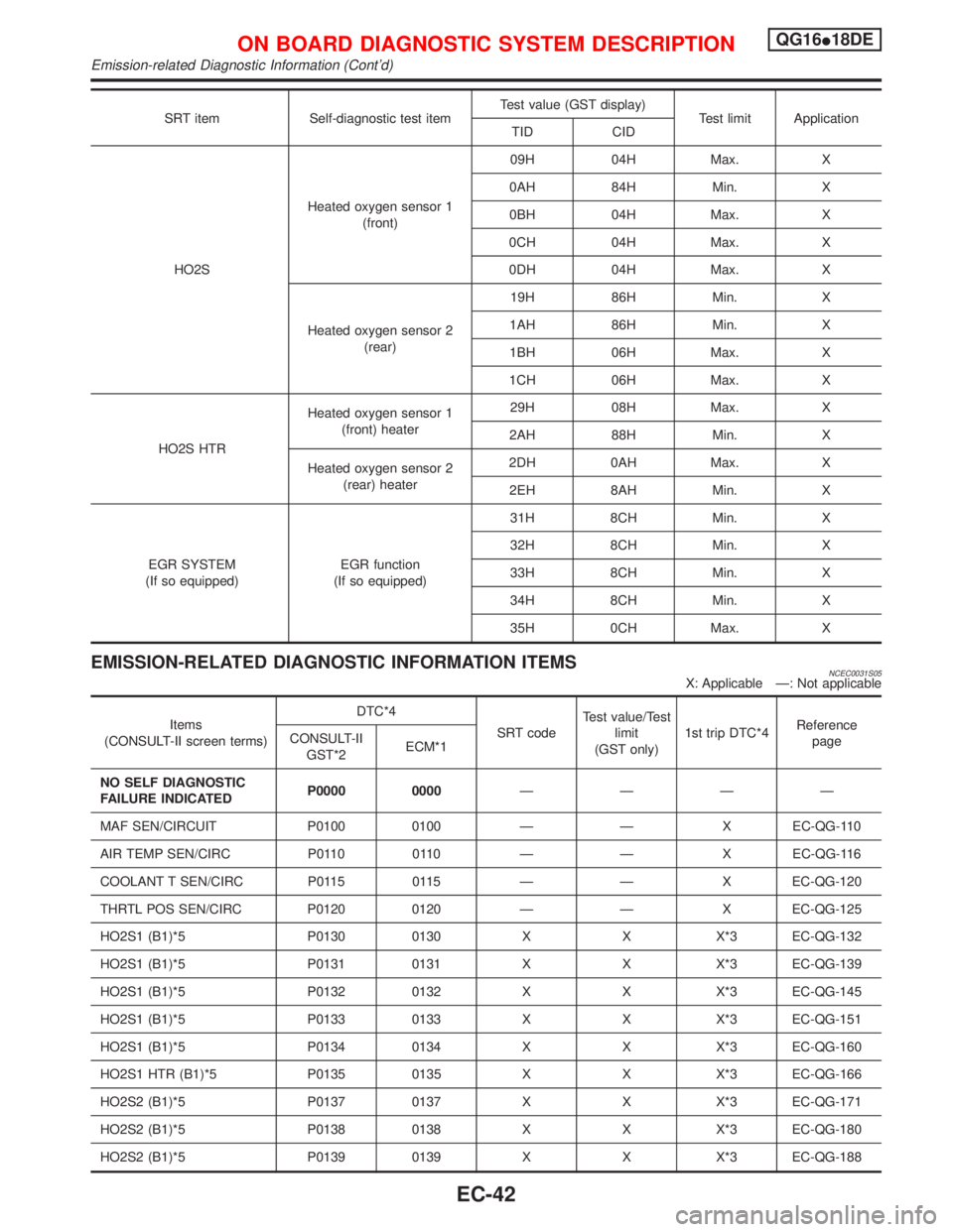
SRT item Self-diagnostic test itemTest value (GST display)
Test limit Application
TID CID
HO2SHeated oxygen sensor 1
(front)09H 04H Max. X
0AH 84H Min. X
0BH 04H Max. X
0CH 04H Max. X
0DH 04H Max. X
Heated oxygen sensor 2
(rear)19H 86H Min. X
1AH 86H Min. X
1BH 06H Max. X
1CH 06H Max. X
HO2S HTRHeated oxygen sensor 1
(front) heater29H 08H Max. X
2AH 88H Min. X
Heated oxygen sensor 2
(rear) heater2DH 0AH Max. X
2EH 8AH Min. X
EGR SYSTEM
(If so equipped)EGR function
(If so equipped)31H 8CH Min. X
32H 8CH Min. X
33H 8CH Min. X
34H 8CH Min. X
35H 0CH Max. X
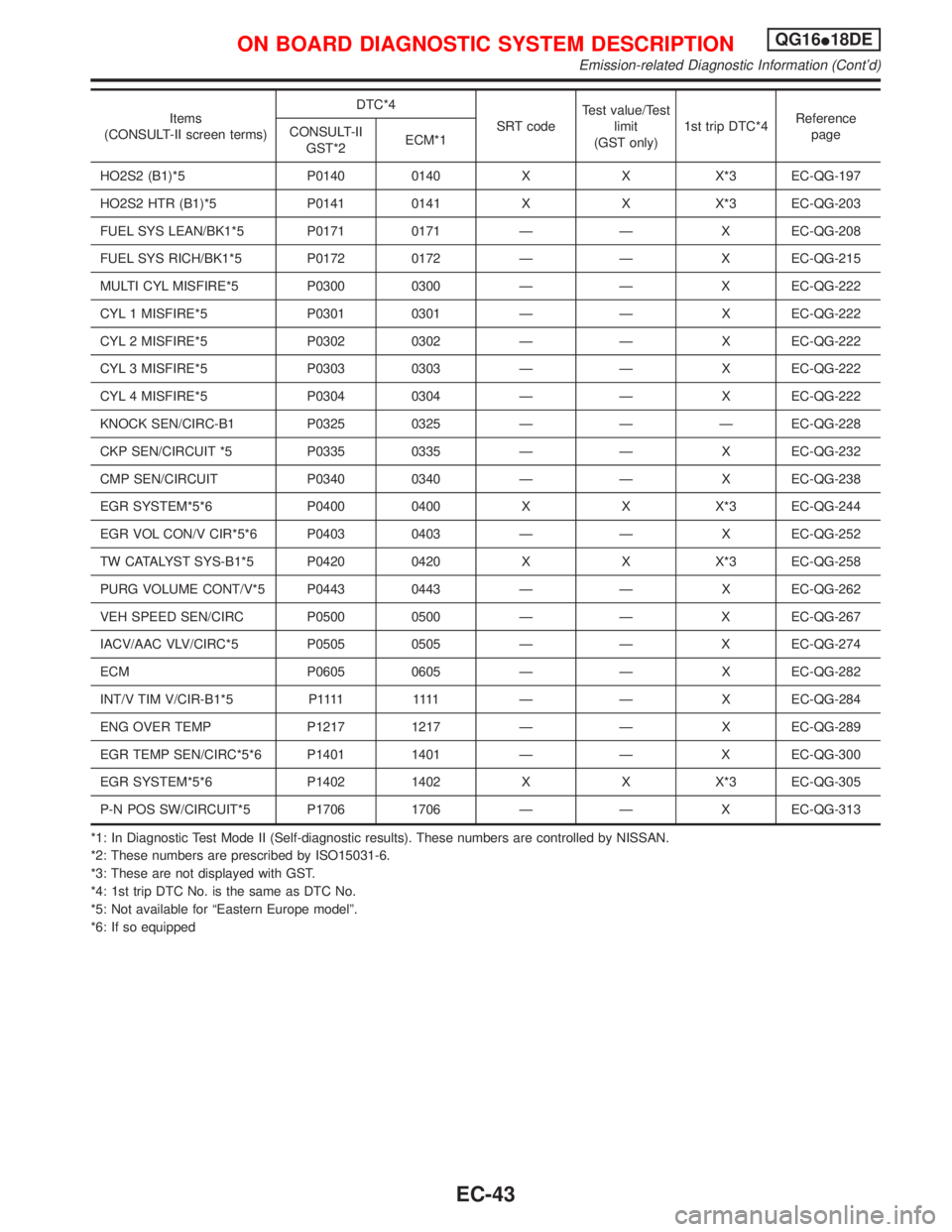
EMISSION-RELATED DIAGNOSTIC INFORMATION ITEMSNCEC0031S05X: Applicable Ð: Not applicable
Items
(CONSULT-II screen terms)DTC*4
SRT codeTest value/Test
limit
(GST only)1st trip DTC*4Reference
page CONSULT-II
GST*2ECM*1
NO SELF DIAGNOSTIC
FAILURE INDICATEDP0000 0000ÐÐÐÐ
MAF SEN/CIRCUIT P0100 0100 Ð Ð X EC-QG-110
AIR TEMP SEN/CIRC P0110 0110 Ð Ð X EC-QG-116
COOLANT T SEN/CIRC P0115 0115 Ð Ð X EC-QG-120
THRTL POS SEN/CIRC P0120 0120 Ð Ð X EC-QG-125
HO2S1 (B1)*5 P0130 0130 X X X*3 EC-QG-132
HO2S1 (B1)*5 P0131 0131 X X X*3 EC-QG-139
HO2S1 (B1)*5 P0132 0132 X X X*3 EC-QG-145
HO2S1 (B1)*5 P0133 0133 X X X*3 EC-QG-151
HO2S1 (B1)*5 P0134 0134 X X X*3 EC-QG-160
HO2S1 HTR (B1)*5 P0135 0135 X X X*3 EC-QG-166
HO2S2 (B1)*5 P0137 0137 X X X*3 EC-QG-171
HO2S2 (B1)*5 P0138 0138 X X X*3 EC-QG-180
HO2S2 (B1)*5 P0139 0139 X X X*3 EC-QG-188
ON BOARD DIAGNOSTIC SYSTEM DESCRIPTIONQG16I18DE
Emission-related Diagnostic Information (Cont'd)
EC-42
Page 485 of 2267
Items
(CONSULT-II screen terms)DTC*4
SRT codeTest value/Test
limit
(GST only)1st trip DTC*4Reference
page CONSULT-II
GST*2ECM*1
HO2S2 (B1)*5 P0140 0140 X X X*3 EC-QG-197
HO2S2 HTR (B1)*5 P0141 0141 X X X*3 EC-QG-203
FUEL SYS LEAN/BK1*5 P0171 0171 Ð Ð X EC-QG-208
FUEL SYS RICH/BK1*5 P0172 0172 Ð Ð X EC-QG-215
MULTI CYL MISFIRE*5 P0300 0300 Ð Ð X EC-QG-222
CYL 1 MISFIRE*5 P0301 0301 Ð Ð X EC-QG-222
CYL 2 MISFIRE*5 P0302 0302 Ð Ð X EC-QG-222
CYL 3 MISFIRE*5 P0303 0303 Ð Ð X EC-QG-222
CYL 4 MISFIRE*5 P0304 0304 Ð Ð X EC-QG-222
KNOCK SEN/CIRC-B1 P0325 0325 Ð Ð Ð EC-QG-228
CKP SEN/CIRCUIT *5 P0335 0335 Ð Ð X EC-QG-232
CMP SEN/CIRCUIT P0340 0340 Ð Ð X EC-QG-238
EGR SYSTEM*5*6 P0400 0400 X X X*3 EC-QG-244
EGR VOL CON/V CIR*5*6 P0403 0403 Ð Ð X EC-QG-252
TW CATALYST SYS-B1*5 P0420 0420 X X X*3 EC-QG-258
PURG VOLUME CONT/V*5 P0443 0443 Ð Ð X EC-QG-262
VEH SPEED SEN/CIRC P0500 0500 Ð Ð X EC-QG-267
IACV/AAC VLV/CIRC*5 P0505 0505 Ð Ð X EC-QG-274
ECM P0605 0605 Ð Ð X EC-QG-282
INT/V TIM V/CIR-B1*5 P1111 1111 Ð Ð XEC-QG-284
ENG OVER TEMP P1217 1217 Ð Ð X EC-QG-289
EGR TEMP SEN/CIRC*5*6 P1401 1401 Ð Ð X EC-QG-300
EGR SYSTEM*5*6 P1402 1402 X X X*3 EC-QG-305
P-N POS SW/CIRCUIT*5 P1706 1706 Ð Ð X EC-QG-313
*1: In Diagnostic Test Mode II (Self-diagnostic results). These numbers are controlled by NISSAN.
*2: These numbers are prescribed by ISO15031-6.
*3: These are not displayed with GST.
*4: 1st trip DTC No. is the same as DTC No.
*5: Not available for ªEastern Europe modelº.
*6: If so equipped
ON BOARD DIAGNOSTIC SYSTEM DESCRIPTIONQG16I18DE
Emission-related Diagnostic Information (Cont'd)
EC-43
Page 486 of 2267
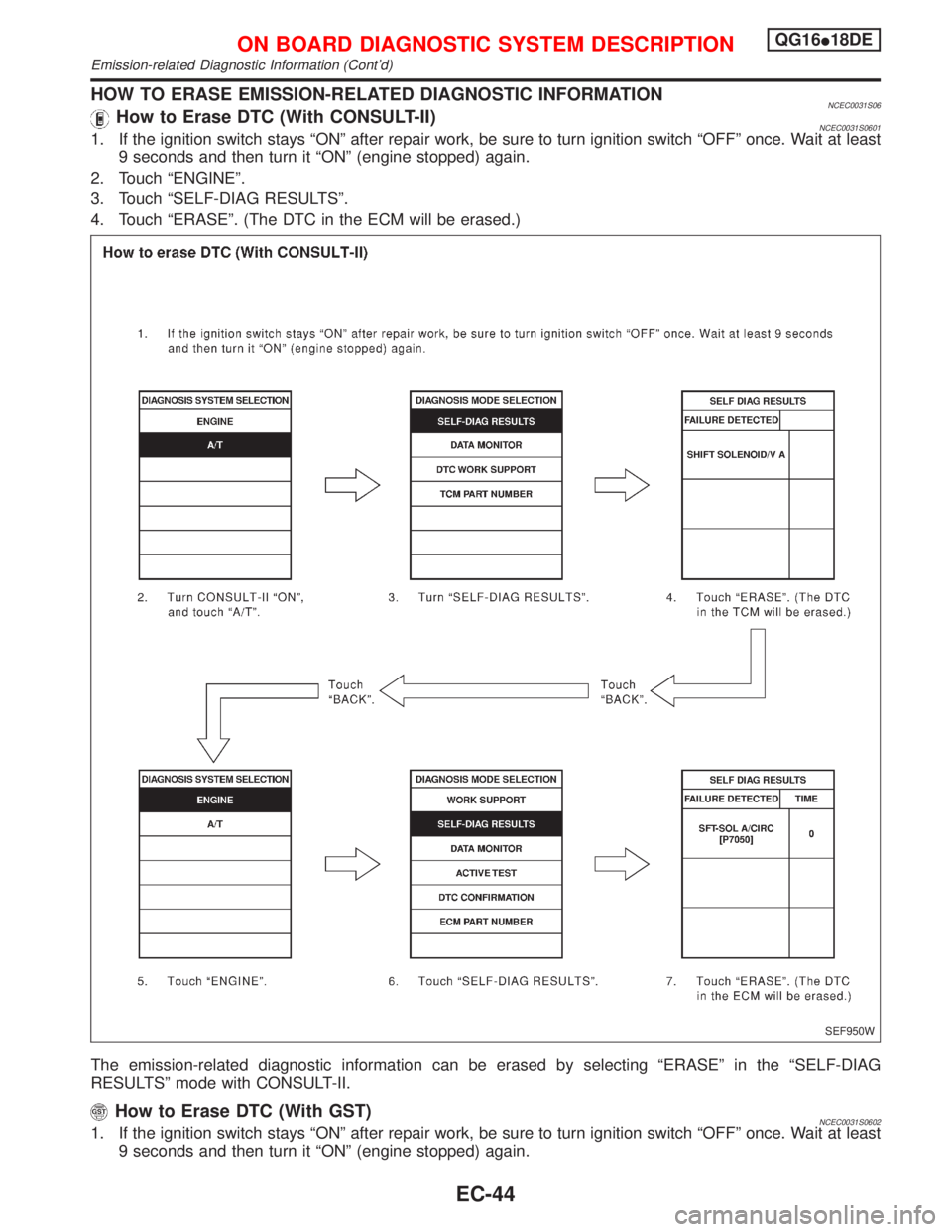
HOW TO ERASE EMISSION-RELATED DIAGNOSTIC INFORMATIONNCEC0031S06How to Erase DTC (With CONSULT-II)NCEC0031S06011. If the ignition switch stays ªONº after repair work, be sure to turn ignition switch ªOFFº once. Wait at least
9 seconds and then turn it ªONº (engine stopped) again.
2. Touch ªENGINEº.
3. Touch ªSELF-DIAG RESULTSº.
4. Touch ªERASEº. (The DTC in the ECM will be erased.)
The emission-related diagnostic information can be erased by selecting ªERASEº in the ªSELF-DIAG
RESULTSº mode with CONSULT-II.
How to Erase DTC (With GST)NCEC0031S06021. If the ignition switch stays ªONº after repair work, be sure to turn ignition switch ªOFFº once. Wait at least
9 seconds and then turn it ªONº (engine stopped) again.
SEF950W
ON BOARD DIAGNOSTIC SYSTEM DESCRIPTIONQG16I18DE
Emission-related Diagnostic Information (Cont'd)
EC-44
Page 487 of 2267
2. Select Mode 4 with GST (Generic Scan Tool).
The emission-related diagnostic information can be erased by selecting Mode 4 with GST (Generic Scan Tool).
How to Erase DTC (No Tools)NCEC0031S06031. If the ignition switch stays ªONº after repair work, be sure to turn ignition switch ªOFFº once. Wait at least
9 seconds and then turn it ªONº again.
2. Change the diagnostic test mode from Mode II to Mode I by using the data link connector. (See EC-QG-
48.)
The emission-related diagnostic information can be erased by changing the diagnostic test mode from Diag-
nostic Test Mode II to Mode I by using the data link connector. (Refer to EC-QG-48.)
NOTE:
IIf the battery is disconnected, the emission-related diagnostic information will be lost after approx.
24 hours.
IErasing the emission-related diagnostic information using CONSULT-II or GST is easier and
quicker than switching the mode using the data link connector.
IThe following data are cleared when the ECM memory is erased.
1) Diagnostic trouble codes
2) 1st trip diagnostic trouble codes
3) Freeze frame data
4) 1st trip freeze frame data
5) System readiness test (SRT) codes
6) Test values
7) Distance traveled while MI is activated
8) Others
Actual work procedures are explained using a DTC as an example. Be careful so that not only the DTC, but
all of the data listed above, are cleared from the ECM memory during work procedures.
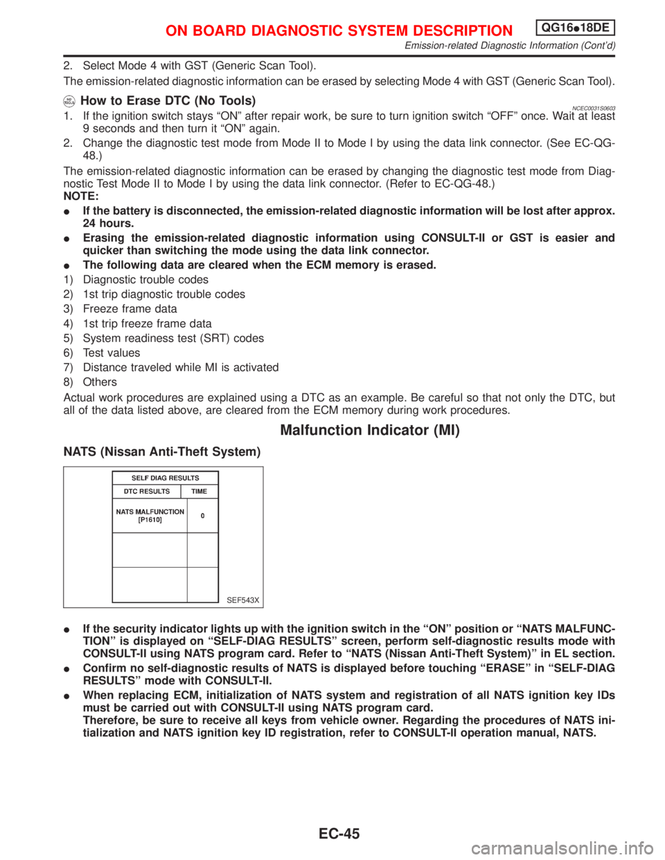
Malfunction Indicator (MI)
NATS (Nissan Anti-Theft System)
IIf the security indicator lights up with the ignition switch in the ªONº position or ªNATS MALFUNC-
TIONº is displayed on ªSELF-DIAG RESULTSº screen, perform self-diagnostic results mode with
CONSULT-II using NATS program card. Refer to ªNATS (Nissan Anti-Theft System)º in EL section.
IConfirm no self-diagnostic results of NATS is displayed before touching ªERASEº in ªSELF-DIAG
RESULTSº mode with CONSULT-II.
IWhen replacing ECM, initialization of NATS system and registration of all NATS ignition key IDs
must be carried out with CONSULT-II using NATS program card.
Therefore, be sure to receive all keys from vehicle owner. Regarding the procedures of NATS ini-
tialization and NATS ignition key ID registration, refer to CONSULT-II operation manual, NATS.
SEF543X
ON BOARD DIAGNOSTIC SYSTEM DESCRIPTIONQG16I18DE
Emission-related Diagnostic Information (Cont'd)
EC-45
Page 488 of 2267
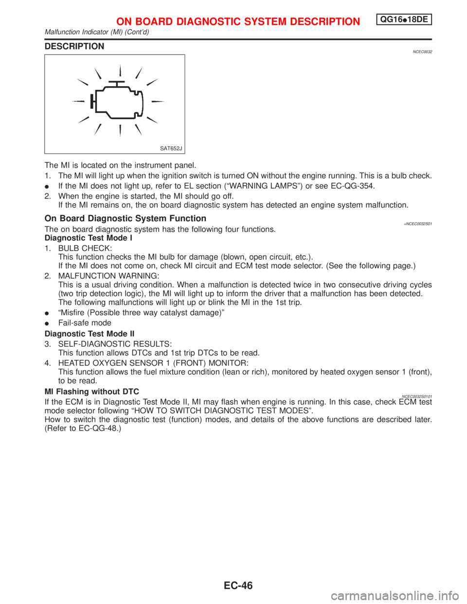
DESCRIPTIONNCEC0032
The MI is located on the instrument panel.
1. The MI will light up when the ignition switch is turned ON without the engine running. This is a bulb check.
IIf the MI does not light up, refer to EL section (ªWARNING LAMPSº) or see EC-QG-354.
2. When the engine is started, the MI should go off.
If the MI remains on, the on board diagnostic system has detected an engine system malfunction.
On Board Diagnostic System Function=NCEC0032S01The on board diagnostic system has the following four functions.
Diagnostic Test Mode I
1. BULB CHECK:
This function checks the MI bulb for damage (blown, open circuit, etc.).
If the MI does not come on, check MI circuit and ECM test mode selector. (See the following page.)
2. MALFUNCTION WARNING:
This is a usual driving condition. When a malfunction is detected twice in two consecutive driving cycles
(two trip detection logic), the MI will light up to inform the driver that a malfunction has been detected.
The following malfunctions will light up or blink the MI in the 1st trip.
IªMisfire (Possible three way catalyst damage)º
IFail-safe mode
Diagnostic Test Mode II
3. SELF-DIAGNOSTIC RESULTS:
This function allows DTCs and 1st trip DTCs to be read.
4. HEATED OXYGEN SENSOR 1 (FRONT) MONITOR:
This function allows the fuel mixture condition (lean or rich), monitored by heated oxygen sensor 1 (front),
to be read.
MI Flashing without DTC
NCEC0032S0101If the ECM is in Diagnostic Test Mode II, MI may flash when engine is running. In this case, check ECM test
mode selector following ªHOW TO SWITCH DIAGNOSTIC TEST MODESº.
How to switch the diagnostic test (function) modes, and details of the above functions are described later.
(Refer to EC-QG-48.)
SAT652J
ON BOARD DIAGNOSTIC SYSTEM DESCRIPTIONQG16I18DE
Malfunction Indicator (MI) (Cont'd)
EC-46
Page 489 of 2267
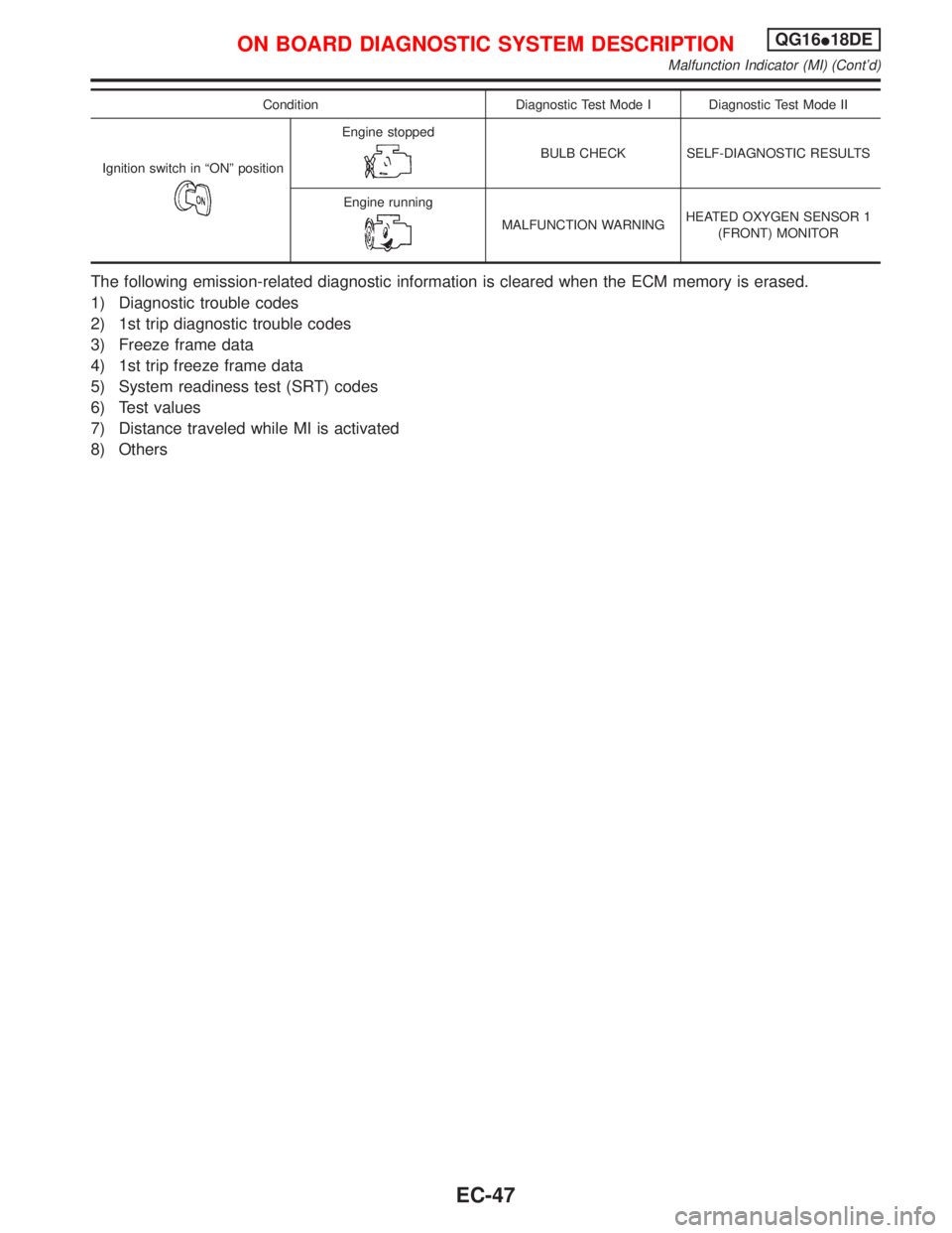
Condition Diagnostic Test Mode I Diagnostic Test Mode II
Ignition switch in ªONº position
Engine stopped
BULB CHECK SELF-DIAGNOSTIC RESULTS
Engine running
MALFUNCTION WARNINGHEATED OXYGEN SENSOR 1
(FRONT) MONITOR
The following emission-related diagnostic information is cleared when the ECM memory is erased.
1) Diagnostic trouble codes
2) 1st trip diagnostic trouble codes
3) Freeze frame data
4) 1st trip freeze frame data
5) System readiness test (SRT) codes
6) Test values
7) Distance traveled while MI is activated
8) Others
ON BOARD DIAGNOSTIC SYSTEM DESCRIPTIONQG16I18DE
Malfunction Indicator (MI) (Cont'd)
EC-47
Page 490 of 2267
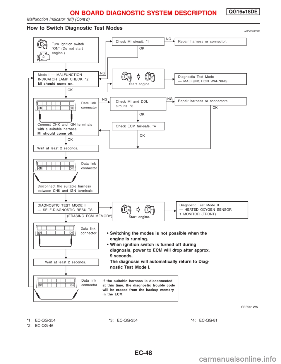
How to Switch Diagnostic Test ModesNCEC0032S02
*1: EC-QG-354
*2: EC-QG-46*3: EC-QG-354 *4: EC-QG-81
SEF951WA
ON BOARD DIAGNOSTIC SYSTEM DESCRIPTIONQG16I18DE
Malfunction Indicator (MI) (Cont'd)
EC-48