Int NISSAN TEANA 2008 Service Manual
[x] Cancel search | Manufacturer: NISSAN, Model Year: 2008, Model line: TEANA, Model: NISSAN TEANA 2008Pages: 5121, PDF Size: 69.03 MB
Page 893 of 5121
BCS-76
< SYMPTOM DIAGNOSIS >
COMBINATION SWITCH SYSTEM SYMPTOMS
SYMPTOM DIAGNOSIS
COMBINATION SWITCH SYSTEM SYMPTOMS
Symptom TableINFOID:0000000003809632
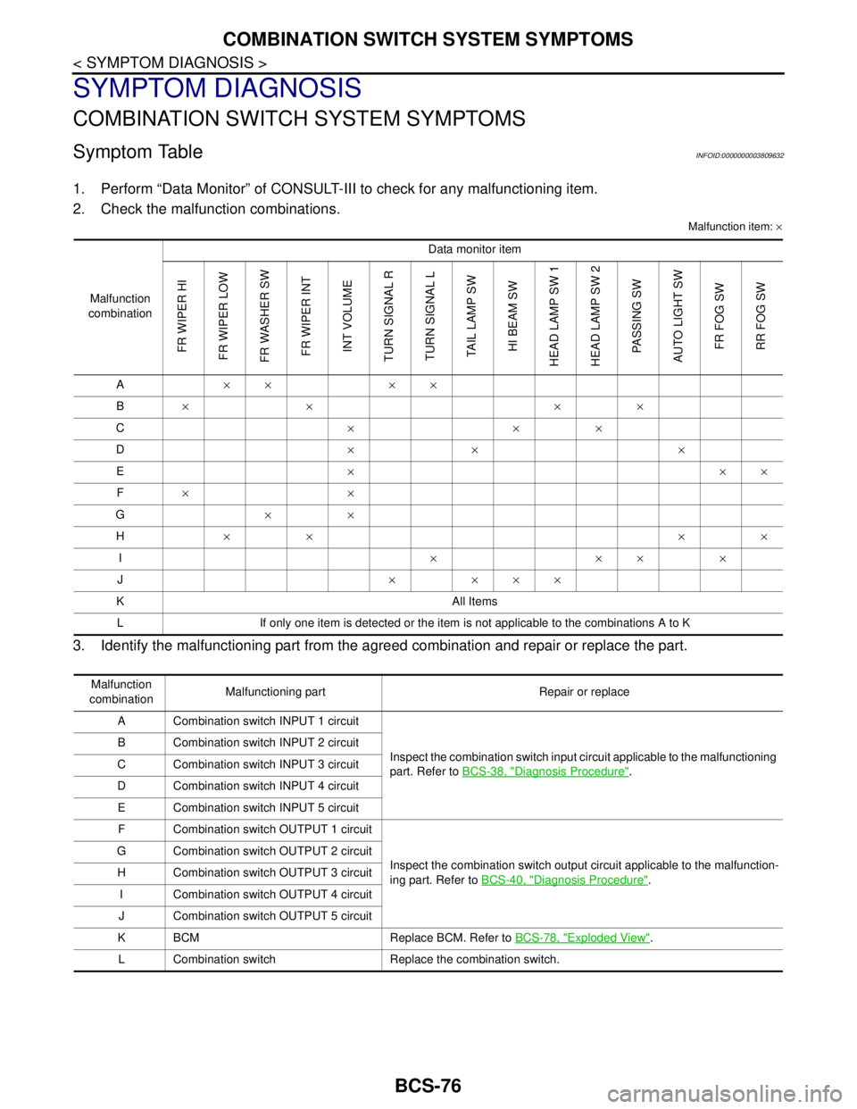
1. Perform “Data Monitor” of CONSULT-III to check for any malfunctioning item.
2. Check the malfunction combinations.
Malfunction item: ×
3. Identify the malfunctioning part from the agreed combination and repair or replace the part.
Malfunction
combinationData monitor item
FR WIPER HI
FR WIPER LOW
FR WASHER SW
FR WIPER INT
INT VOLUME
TURN SIGNAL R
TURN SIGNAL L
TAIL LAMP SW
HI BEAM SW
HEAD LAMP SW 1
HEAD LAMP SW 2
PASSING SW
AUTO LIGHT SW
FR FOG SW
RR FOG SW
A×× ××
B×× ××
C×××
D×× ×
E×××
F××
G××
H×× ××
I××××
J× ×××
K All Items
L If only one item is detected or the item is not applicable to the combinations A to K
Malfunction
combinationMalfunctioning part Repair or replace
A Combination switch INPUT 1 circuit
Inspect the combination switch input circuit applicable to the malfunctioning
part. Refer to BCS-38, "
Diagnosis Procedure". B Combination switch INPUT 2 circuit
C Combination switch INPUT 3 circuit
D Combination switch INPUT 4 circuit
E Combination switch INPUT 5 circuit
F Combination switch OUTPUT 1 circuit
Inspect the combination switch output circuit applicable to the malfunction-
ing part. Refer to BCS-40, "
Diagnosis Procedure". G Combination switch OUTPUT 2 circuit
H Combination switch OUTPUT 3 circuit
I Combination switch OUTPUT 4 circuit
J Combination switch OUTPUT 5 circuit
K BCM Replace BCM. Refer to BCS-78, "
Exploded View".
L Combination switch Replace the combination switch.
Page 894 of 5121
BCS
PRECAUTIONS
BCS-77
< PRECAUTION >
C
D
E
F
G
H
I
J
K
L B A
O
P N
PRECAUTION
PRECAUTIONS
Precaution for Supplemental Restraint System (SRS) "AIR BAG" and "SEAT BELT
PRE-TENSIONER"
INFOID:0000000003809633
The Supplemental Restraint System such as “AIR BAG” and “SEAT BELT PRE-TENSIONER”, used along
with a front seat belt, helps to reduce the risk or severity of injury to the driver and front passenger for certain
types of collision. This system includes seat belt switch inputs and dual stage front air bag modules. The SRS
system uses the seat belt switches to determine the front air bag deployment, and may only deploy one front
air bag, depending on the severity of a collision and whether the front occupants are belted or unbelted.
Information necessary to service the system safely is included in the “SRS AIRBAG” and “SEAT BELT” of this
Service Manual.
WARNING:
To avoid rendering the SRS inoperative, which could increase the risk of personal injury or death in
the event of a collision which would result in air bag inflation, all maintenance must be performed by
an authorized NISSAN/INFINITI dealer.
Improper maintenance, including incorrect removal and installation of the SRS, can lead to personal
injury caused by unintentional activation of the system. For removal of Spiral Cable and Air Bag
Module, see the “SRS AIRBAG”.
Never use electrical test equipment on any circuit related to the SRS unless instructed to in this Ser-
vice Manual. SRS wiring harnesses can be identified by yellow and/or orange harnesses or harness
connectors.
Page 895 of 5121
BCS-78
< ON-VEHICLE REPAIR >
BCM (BODY CONTROL MODULE)
ON-VEHICLE REPAIR
BCM (BODY CONTROL MODULE)
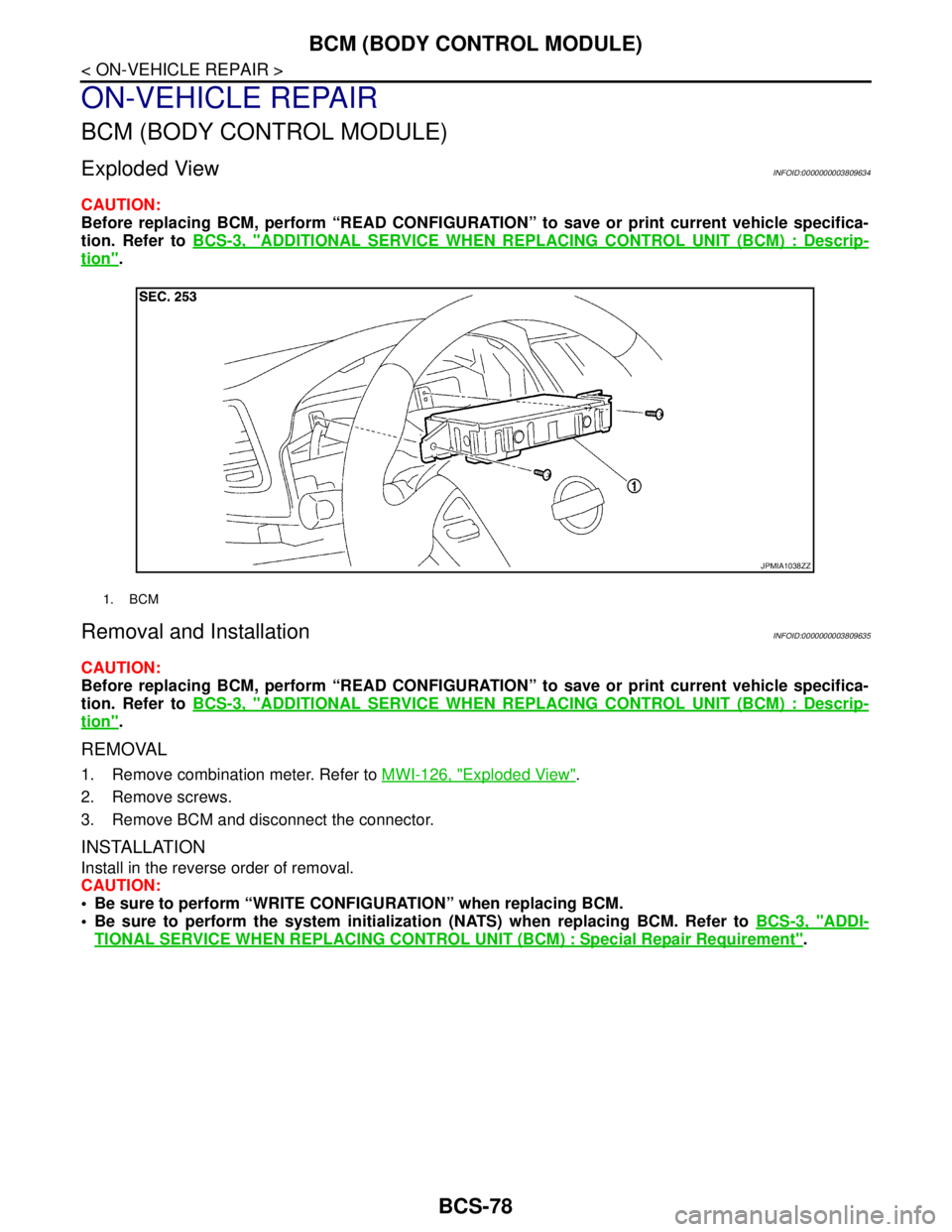
Exploded ViewINFOID:0000000003809634
CAUTION:
Before replacing BCM, perform “READ CONFIGURATION” to save or print current vehicle specifica-
tion. Refer to BCS-3, "
ADDITIONAL SERVICE WHEN REPLACING CONTROL UNIT (BCM) : Descrip-
tion".
Removal and InstallationINFOID:0000000003809635
CAUTION:
Before replacing BCM, perform “READ CONFIGURATION” to save or print current vehicle specifica-
tion. Refer to BCS-3, "
ADDITIONAL SERVICE WHEN REPLACING CONTROL UNIT (BCM) : Descrip-
tion".
REMOVAL
1. Remove combination meter. Refer to MWI-126, "Exploded View".
2. Remove screws.
3. Remove BCM and disconnect the connector.
INSTALLATION
Install in the reverse order of removal.
CAUTION:
Be sure to perform “WRITE CONFIGURATION” when replacing BCM.
Be sure to perform the system initialization (NATS) when replacing BCM. Refer to BCS-3, "
ADDI-
TIONAL SERVICE WHEN REPLACING CONTROL UNIT (BCM) : Special Repair Requirement".
1. BCM
JPMIA1038ZZ
Page 897 of 5121
BR-1
BRAKES
C
DE
G H
I
J
K L
M
SECTION BR
A
B
BR
N
O P
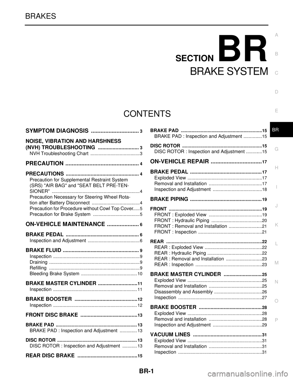
CONTENTS
BRAKE SYSTEM
SYMPTOM DIAGNOSIS ..... ..........................3
NOISE, VIBRATION AND HARSHNESS
(NVH) TROUBLESHOOTING ........................ .....
3
NVH Troubleshooting Chart ................................ ......3
PRECAUTION ...............................................4
PRECAUTIONS .............................................. .....4
Precaution for Supplemental Restraint System
(SRS) "AIR BAG" and "SEAT BELT PRE-TEN-
SIONER" ............................................................. ......
4
Precaution Necessary for Steering Wheel Rota-
tion after Battery Disconnect .....................................
4
Precaution for Procedure without Cowl Top Cover ......5
Precaution for Brake System ....................................5
ON-VEHICLE MAINTENANCE .....................6
BRAKE PEDAL .............................................. .....6
Inspection and Adjustment .................................. ......6
BRAKE FLUID .....................................................9
Inspection ............................................................ ......9
Draining .....................................................................9
Refilling .....................................................................9
Bleeding Brake System ...........................................10
BRAKE MASTER CYLINDER ........................ ....11
Inspection ............................................................ ....11
BRAKE BOOSTER ............................................12
Inspection ............................................................ ....12
FRONT DISC BRAKE .................................... ....13
BRAKE PAD .......................................................... ....13
BRAKE PAD : Inspection and Adjustment ..............13
DISC ROTOR ......................................................... ....13
DISC ROTOR : Inspection and Adjustment ............13
REAR DISC BRAKE ...................................... ....15
BRAKE PAD .......................................................... ....15
BRAKE PAD : Inspection and Adjustment ...............15
DISC ROTOR ......................................................... ....15
DISC ROTOR : Inspection and Adjustment .............15
ON-VEHICLE REPAIR .................................17
BRAKE PEDAL ................................ .................17
Exploded View ..................................................... ....17
Removal and Installation .........................................17
Inspection and Adjustment ......................................18
BRAKE PIPING ................................ .................19
FRONT ................................................................... ....19
FRONT : Exploded View .........................................19
FRONT : Hydraulic Piping .......................................20
FRONT : Removal and Installation ..........................21
FRONT : Inspection .................................................21
REAR ..................................................................... ....22
REAR : Exploded View ............................................22
REAR : Hydraulic Piping ..........................................22
REAR : Removal and Installation ............................23
REAR : Inspection ...................................................23
BRAKE MASTER CYLINDER ..........................25
Exploded View .........................................................25
Removal and Installation .........................................25
Disassembly and Assembly .....................................26
Inspection ................................................................27
BRAKE BOOSTER ...........................................28
Exploded View ..................................................... ....28
Removal and installation .........................................28
Inspection and Adjustment ......................................29
VACUUM LINES ...............................................31
Exploded View .........................................................31
Removal and Installation .........................................31
Inspection ................................................................31
Page 900 of 5121
BR-4
< PRECAUTION >
PRECAUTIONS
PRECAUTION
PRECAUTIONS
Precaution for Supplemental Restraint System (SRS) "AIR BAG" and "SEAT BELT
PRE-TENSIONER"
INFOID:0000000003890160
The Supplemental Restraint System such as “AIR BAG” and “SEAT BELT PRE-TENSIONER”, used along
with a front seat belt, helps to reduce the risk or severity of injury to the driver and front passenger for certain
types of collision. Information necessary to service the system safely is included in the “SRS AIRBAG” and
“SEAT BELT” of this Service Manual.
WARNING:
• To avoid rendering the SRS inoperative, which could increase the risk of personal injury or death in
the event of a collision which would result in air bag inflation, all maintenance must be performed by
an authorized NISSAN/INFINITI dealer.
Improper maintenance, including incorrect removal and installation of the SRS, can lead to personal
injury caused by unintentional activation of the system. For removal of Spiral Cable and Air Bag
Module, see the “SRS AIRBAG”.
Never use electrical test equipment on any circuit related to the SRS unless instructed to in this Ser-
vice Manual. SRS wiring harnesses can be identified by yellow and/or orange harnesses or harness
connectors.
Precaution Necessary for Steering Wheel Rotation after Battery Disconnect
INFOID:0000000003890161
NOTE:
Before removing and installing any control units, first turn the push-button ignition switch to the LOCK posi-
tion, then disconnect both battery cables.
After finishing work, confirm that all control unit connectors are connected properly, then re-connect both
battery cables.
Always use CONSULT-III to perform self-diagnosis as a part of each function inspection after finishing work.
If a DTC is detected, perform trouble diagnosis according to self-diagnosis results.
This vehicle is equipped with a push-button ignition switch and a steering lock unit.
If the battery is disconnected or discharged, the steering wheel will lock and cannot be turned.
If turning the steering wheel is required with the battery disconnected or discharged, follow the procedure
below before starting the repair operation.
OPERATION PROCEDURE
1. Connect both battery cables.
NOTE:
Supply power using jumper cables if battery is discharged.
2. Turn the push-button ignition switch to ACC position.
(At this time, the steering lock will be released.)
3. Disconnect both battery cables. The steering lock will remain released with both battery cables discon-
nected and the steering wheel can be turned.
4. Perform the necessary repair operation.
5. When the repair work is completed, re-connect both battery cables. With the brake pedal released, turn
the push-button ignition switch from ACC position to ON position, then to LOCK position. (The steering
wheel will lock when the push-button ignition switch is turned to LOCK position.)
6. Perform self-diagnosis check of all control units using CONSULT-III.
Page 901 of 5121
PRECAUTIONS
BR-5
< PRECAUTION >
C
D
E
G
H
I
J
K
L
MA
B
BR
N
O
P
Precaution for Procedure without Cowl Top CoverINFOID:0000000003890162
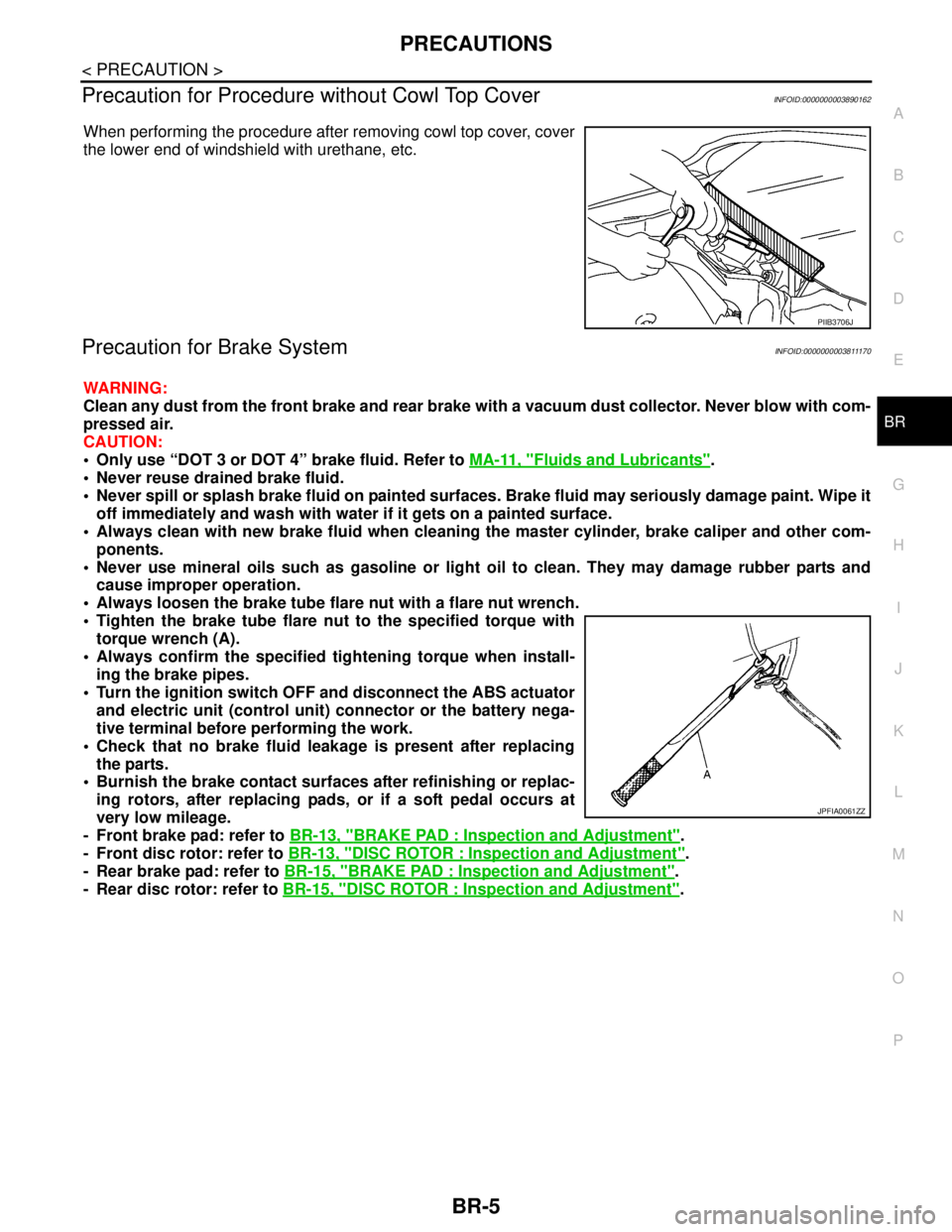
When performing the procedure after removing cowl top cover, cover
the lower end of windshield with urethane, etc.
Precaution for Brake SystemINFOID:0000000003811170
WARNING:
Clean any dust from the front brake and rear brake with a vacuum dust collector. Never blow with com-
pressed air.
CAUTION:
Only use “DOT 3 or DOT 4” brake fluid. Refer to MA-11, "
Fluids and Lubricants".
Never reuse drained brake fluid.
Never spill or splash brake fluid on painted surfaces. Brake fluid may seriously damage paint. Wipe it
off immediately and wash with water if it gets on a painted surface.
Always clean with new brake fluid when cleaning the master cylinder, brake caliper and other com-
ponents.
Never use mineral oils such as gasoline or light oil to clean. They may damage rubber parts and
cause improper operation.
Always loosen the brake tube flare nut with a flare nut wrench.
Tighten the brake tube flare nut to the specified torque with
torque wrench (A).
Always confirm the specified tightening torque when install-
ing the brake pipes.
Turn the ignition switch OFF and disconnect the ABS actuator
and electric unit (control unit) connector or the battery nega-
tive terminal before performing the work.
Check that no brake fluid leakage is present after replacing
the parts.
Burnish the brake contact surfaces after refinishing or replac-
ing rotors, after replacing pads, or if a soft pedal occurs at
very low mileage.
- Front brake pad: refer to BR-13, "
BRAKE PAD : Inspection and Adjustment".
- Front disc rotor: refer to BR-13, "
DISC ROTOR : Inspection and Adjustment".
- Rear brake pad: refer to BR-15, "
BRAKE PAD : Inspection and Adjustment".
- Rear disc rotor: refer to BR-15, "
DISC ROTOR : Inspection and Adjustment".
PIIB3706J
JPFIA0061ZZ
Page 902 of 5121

BR-6
< ON-VEHICLE MAINTENANCE >
BRAKE PEDAL
ON-VEHICLE MAINTENANCE
BRAKE PEDAL
Inspection and AdjustmentINFOID:0000000003811172
INSPECTION
Brake Pedal Height
Check the brake pedal height (H1) between the dash lower panel (1)
and the brake pedal upper surface.
CAUTION:
Remove the floor trim.
Stop Lamp Switch and ASCD Brake Switch
Check the clearance (C) between stopper rubber (1) and stop lamp
switch and ASCD brake switch (2) threaded end.
CAUTION:
The stop lamp must be turned off when the brake pedal is
released.
NOTE:
Pull the brake pedal pad to make the clearance between stopper
rubber and stop lamp switch and ASCD brake switch threaded end.
Brake Pedal Play
Press the brake pedal. Check the brake pedal play (A).
Depressed Brake Pedal Height
Check the brake pedal height (H2) between the dash lower panel (1)
and the brake pedal upper surface when depressing the brake pedal
at 490 N (50 kg, 110 lb) while turning engine ON.
CAUTION:
Remove the floor trim.Standard
H
1: Refer to BR-45, "Brake
Pedal".
JPFIA0065ZZ
Standard
C : Refer to BR-45, "
Brake
Pedal".
JPFIA0122ZZ
Standard
A : Refer to BR-45, "
Brake
Pedal".
JPFIA0121ZZ
Standard
H
2: Refer to BR-45, "Brake
Pedal".
JPFIA0068ZZ
Page 903 of 5121
BRAKE PEDAL
BR-7
< ON-VEHICLE MAINTENANCE >
C
D
E
G
H
I
J
K
L
MA
B
BR
N
O
P
ADJUSTMENT
Brake Pedal Height
1. Remove instrument lower panel LH. Refer to IP-11, "Exploded View".
2. Disconnect the stop lamp switch and ASCD brake switch harness connector.
3. Turn the stop lamp switch and ASCD brake switch 45° counterclockwise.
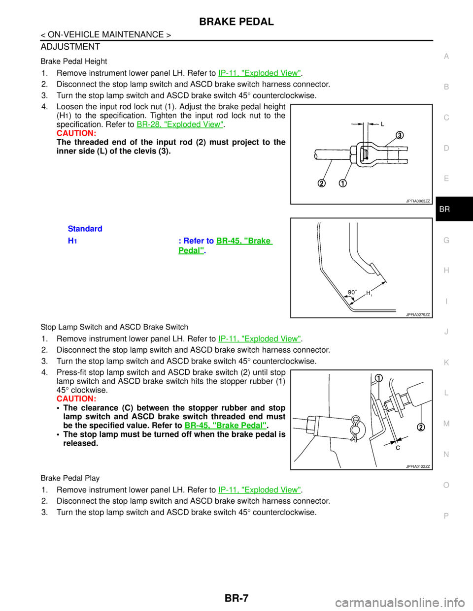
4. Loosen the input rod lock nut (1). Adjust the brake pedal height
(H
1) to the specification. Tighten the input rod lock nut to the
specification. Refer to BR-28, "
Exploded View".
CAUTION:
The threaded end of the input rod (2) must project to the
inner side (L) of the clevis (3).
Stop Lamp Switch and ASCD Brake Switch
1. Remove instrument lower panel LH. Refer to IP-11, "Exploded View".
2. Disconnect the stop lamp switch and ASCD brake switch harness connector.
3. Turn the stop lamp switch and ASCD brake switch 45° counterclockwise.
4. Press-fit stop lamp switch and ASCD brake switch (2) until stop
lamp switch and ASCD brake switch hits the stopper rubber (1)
45° clockwise.
CAUTION:
The clearance (C) between the stopper rubber and stop
lamp switch and ASCD brake switch threaded end must
be the specified value. Refer to BR-45, "
Brake Pedal".
The stop lamp must be turned off when the brake pedal is
released.
Brake Pedal Play
1. Remove instrument lower panel LH. Refer to IP-11, "Exploded View".
2. Disconnect the stop lamp switch and ASCD brake switch harness connector.
3. Turn the stop lamp switch and ASCD brake switch 45° counterclockwise.
JPFIA0003ZZ
Standard
H
1: Refer to BR-45, "Brake
Pedal".
JPFIA0279ZZ
JPFIA0122ZZ
Page 904 of 5121
BR-8
< ON-VEHICLE MAINTENANCE >
BRAKE PEDAL
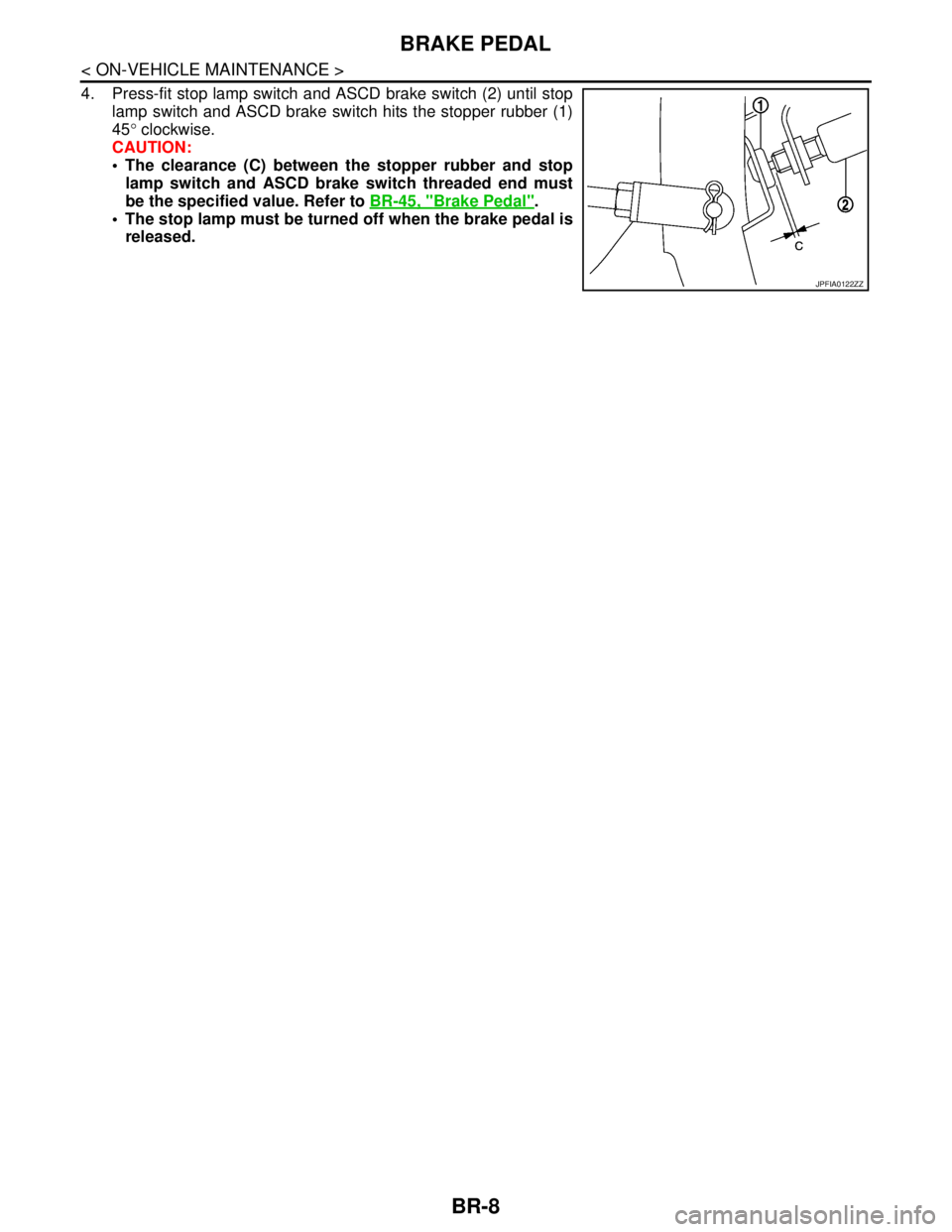
4. Press-fit stop lamp switch and ASCD brake switch (2) until stop
lamp switch and ASCD brake switch hits the stopper rubber (1)
45° clockwise.
CAUTION:
The clearance (C) between the stopper rubber and stop
lamp switch and ASCD brake switch threaded end must
be the specified value. Refer to BR-45, "
Brake Pedal".
The stop lamp must be turned off when the brake pedal is
released.
JPFIA0122ZZ
Page 905 of 5121

BRAKE FLUID
BR-9
< ON-VEHICLE MAINTENANCE >
C
D
E
G
H
I
J
K
L
MA
B
BR
N
O
P
BRAKE FLUID
InspectionINFOID:0000000003811173
BRAKE FLUID LEVEL
Check that the fluid level in the sub tank is within the specified
range (MAX – MIN lines).
Visually check for any brake fluid leakage around the sub tank,
reservoir tank and hose.
Check the brake system for any leakage if the fluid level is
extremely low (lower than MIN).
Check the brake system for fluid leakage if the warning lamp
remains illuminated even after the parking brake is released.
BRAKE LINE
1. Check brake line (tubes and hoses) for cracks, deterioration or other damage. Replace any damaged
parts.
2. Check for fluid leakage by fully depressing brake pedal while
engine is running.
CAUTION:
If leakage occurs around joints, retighten or, if necessary,
replace damaged parts.
DrainingINFOID:0000000003811174
CAUTION:
Never spill or splash brake fluid on painted surfaces. Brake fluid may seriously damage paint. Wipe it
off immediately and wash with water if it gets on a painted surface.
Turn the ignition switch OFF and disconnect the ABS actuator and electric unit (control unit) con-
nector or the battery negative terminal before draining.
1. Connect a vinyl tube to the bleed valve.
2. Depress the brake pedal and loosen the bleeder valve to gradu-
ally discharge brake fluid.
RefillingINFOID:0000000003811175
CAUTION:
Turn the ignition switch OFF and disconnect the ABS actuator and electric unit (control unit) connec-
tor or the battery negative terminal before refilling.
1. Check that there is no foreign material in the sub tank, and refill with new brake fluid.
CAUTION:
Never reuse drained brake fluid.
JPFIA0007ZZ
SBR389C
BRA0007D