Int NISSAN TEANA 2008 Service Manual
[x] Cancel search | Manufacturer: NISSAN, Model Year: 2008, Model line: TEANA, Model: NISSAN TEANA 2008Pages: 5121, PDF Size: 69.03 MB
Page 945 of 5121
BRC-4
Diagnosis Procedure .............................................112
Special Repair Requirement ..................................112
C1145, C1146 YAW RATE/SIDE G SENSOR .113
Description .............................................................113
DTC Logic ..............................................................113
Diagnosis Procedure .............................................113
Component Inspection ...........................................114
Special Repair Requirement ..................................115
C1155 BRAKE FLUID LEVEL SWITCH ..........116
Description .............................................................116
DTC Logic ..............................................................116
Diagnosis Procedure .............................................116
Component Inspection ...........................................117
Special Repair Requirement ..................................117
C1164, C1165 CV SYSTEM ............................118
Description .............................................................118
DTC Logic ..............................................................118
Diagnosis Procedure .............................................118
Component Inspection ...........................................119
Special Repair Requirement ..................................119
C1166, C1167 SV SYSTEM .............................120
Description .............................................................120
DTC Logic ..............................................................120
Diagnosis Procedure .............................................120
Component Inspection ...........................................121
Special Repair Requirement ..................................121
U1000, U1002 CAN COMM CIRCUIT .............122
Description .............................................................122
DTC Logic ..............................................................122
Diagnosis Procedure .............................................122
Special Repair Requirement ..................................122
POWER SUPPLY AND GROUND CIRCUIT ...123
Description .............................................................123
Diagnosis Procedure .............................................123
PARKING BRAKE SWITCH ............................124
Component Function Check ..................................124
Diagnosis Procedure .............................................124
Component Inspection ...........................................124
VDC OFF SWITCH ..........................................126
Description .............................................................126
Component Function Check ..................................126
Diagnosis Procedure .............................................126
Component Inspection ...........................................127
ABS WARNING LAMP ....................................128
Description .............................................................128
Component Function Check ..................................128
Diagnosis Procedure .............................................128
BRAKE WARNING LAMP ...............................129
Description .............................................................129
Component Function Check ..................................129
Diagnosis Procedure .............................................129
VDC OFF INDICATOR LAMP ..........................130
Description ............................................................130
Component Function Check .................................130
Diagnosis Procedure .............................................130
SLIP INDICATOR LAMP ..................................131
Description ............................................................131
Component Function Check .................................131
Diagnosis Procedure .............................................131
ECU DIAGNOSIS ......................................132
ABS ACTUATOR AND ELECTRIC UNIT
(CONTROL UNIT) .............................................
132
Reference Value ...................................................132
Wiring Diagram - BRAKE CONTROL SYSTEM - .136
Fail-Safe ................................................................139
DTC No. Index ......................................................140
SYMPTOM DIAGNOSIS ...........................142
EXCESSIVE ABS FUNCTION OPERATION
FREQUENCY ....................................................
142
Diagnosis Procedure .............................................142
UNEXPECTED PEDAL REACTION .................143
Diagnosis Procedure .............................................143
THE BRAKING DISTANCE IS LONG ..............144
Diagnosis Procedure .............................................144
ABS FUNCTION DOES NOT OPERATE .........145
Diagnosis Procedure .............................................145
PEDAL VIBRATION OR ABS OPERATION
SOUND OCCURS .............................................
146
Diagnosis Procedure .............................................146
VEHICLE JERKS DURING VDC/TCS/ABS
CONTROL ........................................................
147
Diagnosis Procedure .............................................147
NORMAL OPERATING CONDITION ...............148
Description ............................................................148
PRECAUTION ...........................................149
PRECAUTIONS ................................................149
Precaution for Supplemental Restraint System
(SRS) "AIR BAG" and "SEAT BELT PRE-TEN-
SIONER" ...............................................................
149
Precaution for Procedure without Cowl Top Cover .149
Precaution for Brake System ................................149
Precaution for Brake Control .................................150
Precautions for Harness Repair ............................150
ON-VEHICLE REPAIR ..............................151
WHEEL SENSOR .............................................151
FRONT WHEEL SENSOR ......................................151
FRONT WHEEL SENSOR : Exploded View .........151
Page 965 of 5121

BRC-24
< COMPONENT DIAGNOSIS >[ABS]
C1110 ABS ACTUATOR AND ELECTRIC UNIT (CONTROL UNIT)
C1110 ABS ACTUATOR AND ELECTRIC UNIT (CONTROL UNIT)
DTC LogicINFOID:0000000003766745
DTC DETECTION LOGIC
DTC CONFIRMATION PROCEDURE
1.DTC REPRODUCTION PROCEDURE
1. Turn the ignition switch ON.
2. Perform ABS actuator and electric unit (control unit) self-diagnosis.
Is DTC
“C1110” detected?
YES >> Proceed to diagnosis procedure. Refer to BRC-24, "Diagnosis Procedure".
NO >> INSPECTION END
Diagnosis ProcedureINFOID:0000000003766746
1.REPLACE ABS ACTUATOR AND ELECTRIC UNIT (CONTROL UNIT)
CAUTION:
Replace ABS actuator and electric unit (control unit) when self-diagnostic result shows items other
than those applicable.
>> Replace ABS actuator and electric unit (control unit).
DTC Display item Malfunction detected condition Possible cause
C1110 CONTROLLER FAILUREWhen there is an internal malfunction in the ABS actuator
and electric unit (control unit).ABS actuator and electric unit
(control unit)
Page 996 of 5121

PRECAUTIONS
BRC-55
< PRECAUTION >[ABS]
C
D
E
G
H
I
J
K
L
MA
B
BRC
N
O
P
PRECAUTION
PRECAUTIONS
Precaution for Supplemental Restraint System (SRS) "AIR BAG" and "SEAT BELT
PRE-TENSIONER"
INFOID:0000000003893848
The Supplemental Restraint System such as “AIR BAG” and “SEAT BELT PRE-TENSIONER”, used along
with a front seat belt, helps to reduce the risk or severity of injury to the driver and front passenger for certain
types of collision. Information necessary to service the system safely is included in the “SRS AIRBAG” and
“SEAT BELT” of this Service Manual.
WARNING:
To avoid rendering the SRS inoperative, which could increase the risk of personal injury or death in
the event of a collision which would result in air bag inflation, all maintenance must be performed by
an authorized NISSAN/INFINITI dealer.
Improper maintenance, including incorrect removal and installation of the SRS, can lead to personal
injury caused by unintentional activation of the system. For removal of Spiral Cable and Air Bag
Module, see the “SRS AIRBAG”.
Never use electrical test equipment on any circuit related to the SRS unless instructed to in this Ser-
vice Manual. SRS wiring harnesses can be identified by yellow and/or orange harnesses or harness
connectors.
Precaution for Procedure without Cowl Top CoverINFOID:0000000003928740
When performing the procedure after removing cowl top cover, cover
the lower end of windshield with urethane, etc.
Precaution for Brake SystemINFOID:0000000003766860
WARNING:
Clean brake pads and shoes with a waste cloth, then wipe with a dust collector.
Only use “DOT 3” or “DOT 4” brake fluid. Refer to MA-11, "
Fluids and Lubricants".
Never reuse drained brake fluid.
Never spill or splash brake fluid on painted surfaces. Brake fluid may seriously damage paint. Wipe it off
immediately and wash with water if it gets on a painted surface.
Never use mineral oils such as gasoline or light oil. They may damage rubber parts and cause improper
operation.
Always loosen the brake tube flare nut with a flare nut wrench.
Tighten the brake tube flare nut to the specified torque with a flare
nut torque wrench (A).
Always conform the specified tightening torque when installing the
brake pipes.
Brake system is an important safety part. If a brake fluid leak is
detected, always disassemble the affected part. If a malfunction is
detected, replace part with a new one.
Turn the ignition switch OFF and disconnect the ABS actuator and
electric unit (control unit) connector or the battery negative terminal
before performing the work.
PIIB3706J
JPFIA0061ZZ
Page 1034 of 5121

C1110, C1153, C1170 ABS ACTUATOR AND ELECTRIC UNIT (CONTROL UNIT)
BRC-93
< COMPONENT DIAGNOSIS >[VDC/TCS/ABS]
C
D
E
G
H
I
J
K
L
MA
B
BRC
N
O
P
C1110, C1153, C1170 ABS ACTUATOR AND ELECTRIC UNIT (CONTROL
UNIT)
DTC LogicINFOID:0000000003766916
DTC DETECTION LOGIC
DTC CONFIRMATION PROCEDURE
1.DTC REPRODUCTION PROCEDURE
1. Turn the ignition switch ON.
2. Perform ABS actuator and electric unit (control unit) self-diagnosis.
Is DTC
“C 111 0”, “C1153” or “C1170” detected?
YES >> Proceed to diagnosis procedure. Refer to BRC-93, "Diagnosis Procedure".
NO >> INSPECTION END
Diagnosis ProcedureINFOID:0000000003766917
1.REPLACE ABS ACTUATOR AND ELECTRIC UNIT (CONTROL UNIT)
CAUTION:
Replace ABS actuator and electric unit (control unit) when self-diagnostic result shows items other
than those applicable.
>> Replace ABS actuator and electric unit (control unit).
Special Repair RequirementINFOID:0000000003767331
1.ADJUSTMENT OF STEERING ANGLE SENSOR NEUTRAL POSITION
Always perform the neutral position adjustment for the steering angle sensor, when replacing the ABS actua-
tor and electric unit (control unit). Refer to BRC-66, "
ADJUSTMENT OF STEERING ANGLE SENSOR NEU-
TRAL POSITION : Description".
>> END
DTC Display item Malfunction detected condition Possible cause
C1110 CONTROLLER FAILUREWhen there is an internal malfunction in the ABS actuator
and electric unit (control unit).
ABS actuator and electric unit
(control unit) C1153 EMERGENCY BRAKEWhen ABS actuator and electric unit (control unit) is mal-
functioning. (Pressure increase is too much or too little)
C1170 VARIANT CODING In a case where VARIANT CODING is different.
Page 1049 of 5121

BRC-108
< COMPONENT DIAGNOSIS >[VDC/TCS/ABS]
C1142 PRESS SENSOR
C1142 PRESS SENSOR
DescriptionINFOID:0000000003766953
The pressure sensor converts the brake fluid pressure to an electric signal and transmits it to the ABS actuator
and electric unit (control unit). [The pressure sensor is integrated in the ABS actuator and electric unit (control
unit).]
DTC LogicINFOID:0000000003766954
DTC DETECTION LOGIC
DTC CONFIRMATION PROCEDURE
1.DTC REPRODUCTION PROCEDURE
1. Turn the ignition switch ON.
2. Perform ABS actuator and electric unit (control unit) self-diagnosis.
Is DTC
“C1142” detected?
YES >> Proceed to diagnosis procedure. Refer to BRC-108, "Diagnosis Procedure".
NO >> INSPECTION END
Diagnosis ProcedureINFOID:0000000003766955
1.CHECK STOP LAMP SWITCH
Check stop lamp switch. Refer to BRC-99, "
Diagnosis Procedure".
Is the inspection result normal?
YES >> GO TO 2.
NO >> Repair or replace malfunction component.
2.CHECK DATA MONITOR
Check pressure sensor signal. Refer to BRC-108, "
Component Inspection".
Is the inspection result normal?
YES >> GO TO 3.
NO >> Check brake pedal, brake booster, and master cylinder for mount play, looseness, brake system
fluid leakage, etc.
- Brake pedal: Refer to BR-6, "
Inspection and Adjustment".
- Brake booster: Refer to BR-12, "
Inspection".
- Brake master cylinder: Refer to BR-11, "
Inspection".
3.ABS ACTUATOR AND ELECTRIC UNIT (CONTROL UNIT) SELF-DIAGNOSIS
Perform ABS actuator and electric unit (control unit) self-diagnosis.
Is any item indicated on the self-diagnosis display?
YES >> Replace ABS actuator and electric unit (control unit).
NO >> Check ABS actuator and electric unit (control unit) pin terminals for damage or loose connection
with harness connector. If any items are damaged, repair or replace damaged parts.
Component InspectionINFOID:0000000003766956
1.CHECK DATA MONITOR
On “DATA MONITOR”, select “PRESS SENSOR” and check the brake fluid pressure.
DTC Display item Malfunction detected condition Possible cause
C1142 PRESS SEN CIRCUITPressure sensor signal line is open or shorted, or pres-
sure sensor is malfunctioning. Harness or connector
Stop lamp switch
ABS actuator and electric unit
(control unit)
Page 1090 of 5121

PRECAUTIONS
BRC-149
< PRECAUTION >[VDC/TCS/ABS]
C
D
E
G
H
I
J
K
L
MA
B
BRC
N
O
P
PRECAUTION
PRECAUTIONS
Precaution for Supplemental Restraint System (SRS) "AIR BAG" and "SEAT BELT
PRE-TENSIONER"
INFOID:0000000003893849
The Supplemental Restraint System such as “AIR BAG” and “SEAT BELT PRE-TENSIONER”, used along
with a front seat belt, helps to reduce the risk or severity of injury to the driver and front passenger for certain
types of collision. Information necessary to service the system safely is included in the “SRS AIRBAG” and
“SEAT BELT” of this Service Manual.
WARNING:
To avoid rendering the SRS inoperative, which could increase the risk of personal injury or death in
the event of a collision which would result in air bag inflation, all maintenance must be performed by
an authorized NISSAN/INFINITI dealer.
Improper maintenance, including incorrect removal and installation of the SRS, can lead to personal
injury caused by unintentional activation of the system. For removal of Spiral Cable and Air Bag
Module, see the “SRS AIRBAG”.
Never use electrical test equipment on any circuit related to the SRS unless instructed to in this Ser-
vice Manual. SRS wiring harnesses can be identified by yellow and/or orange harnesses or harness
connectors.
Precaution for Procedure without Cowl Top CoverINFOID:0000000003928809
When performing the procedure after removing cowl top cover, cover
the lower end of windshield with urethane, etc.
Precaution for Brake SystemINFOID:0000000003767031
WARNING:
Clean brake pads and shoes with a waste cloth, then wipe with a dust collector.
Only use “DOT 3” or “DOT 4” brake fluid. Refer to MA-11, "
Fluids and Lubricants".
Never reuse drained brake fluid.
Never spill or splash brake fluid on painted surfaces. Brake fluid may seriously damage paint. Wipe it off
immediately and wash with water if it gets on a painted surface.
Never use mineral oils such as gasoline or light oil. They may damage rubber parts and cause improper
operation.
Always loosen the brake tube flare nut with a flare nut wrench.
Tighten the brake tube flare nut to the specified torque with a flare
nut torque wrench (A).
Always conform the specified tightening torque when installing the
brake pipes.
Brake system is an important safety part. If a brake fluid leak is
detected, always disassemble the affected part. If a malfunction is
detected, replace part with a new one.
Turn the ignition switch OFF and disconnect the ABS actuator and
electric unit (control unit) connector or the battery negative terminal
before performing the work.
PIIB3706J
JPFIA0061ZZ
Page 1099 of 5121
CHG
CHG-1
ELECTRICAL & POWER CONTROL
C
DE
F
G H
I
J
K L
B
SECTION CHG
A
O P
N
CONTENTS
CHARGING SYSTEM
BASIC INSPECTION .......
.............................2
DIAGNOSIS AND REPAIR WORKFLOW ..... .....2
Work Flow ........................................................... ......2
FUNCTION DIAGNOSIS ...............................5
CHARGING SYSTEM ..................................... .....5
System Diagram .................................................. ......5
System Description ...................................................5
Component Parts Location ........................................5
Component Description ............................................5
POWER GENERATION VOLTAGE VARI-
ABLE CONTROL SYSTEM ............................ .....
7
System Diagram .................................................. ......7
System Description ...................................................7
Component Parts Location ........................................7
Component Description .............................................8
COMPONENT DIAGNOSIS ..........................9
B TERMINAL CIRCUIT .................................. .....9
Description .......................................................... ......9
Diagnosis Procedure .................................................9
L TERMINAL CIRCUIT (OPEN) .........................10
Description .......................................................... ....10
Diagnosis Procedure ...............................................10
L TERMINAL CIRCUIT (SHORT) .......................12
Description .......................................................... ....12
Diagnosis Procedure ...............................................12
S TERMINAL CIRCUIT ......................................13
Description .......................................................... ....13
Diagnosis Procedure ...............................................13
CHARGING SYSTEM ..................................... ....14
Wiring Diagram - CHARGING SYSTEM - ........... ....14
SYMPTOM DIAGNOSIS ..............................17
CHARGING SYSTEM .......................................17
Symptom Table ................................................... ....17
PRECAUTION ..............................................18
PRECAUTIONS .................................................18
Precaution for Supplemental Restraint System
(SRS) "AIR BAG" and "SEAT BELT PRE-TEN-
SIONER" ............................................................. ....
18
PREPARATION ...........................................19
PREPARATION .................................................19
Special Service Tools .......................................... ....19
ON-VEHICLE MAINTENANCE ....................20
CHARGING SYSTEM PRELIMINARY IN-
SPECTION ....... ................................ .................
20
Inspection Procedure ........................................... ....20
ON-VEHICLE REPAIR .................................21
ALTERNATOR . ................................ .................21
Exploded View ..................................................... ....21
Removal and Installation .........................................22
Disassembly and Assembly .....................................23
Inspection ................................................................24
SERVICE DATA AND SPECIFICATIONS
(SDS) ............... .............................................
25
SERVICE DATA AND SPECIFICATIONS
(SDS) .................................................................
25
Alternator ............................................................. ....25
Page 1101 of 5121
CHG
DIAGNOSIS AND REPAIR WORKFLOW
CHG-3
< BASIC INSPECTION >
C
D
E
F
G
H
I
J
K
L B A
O
P N
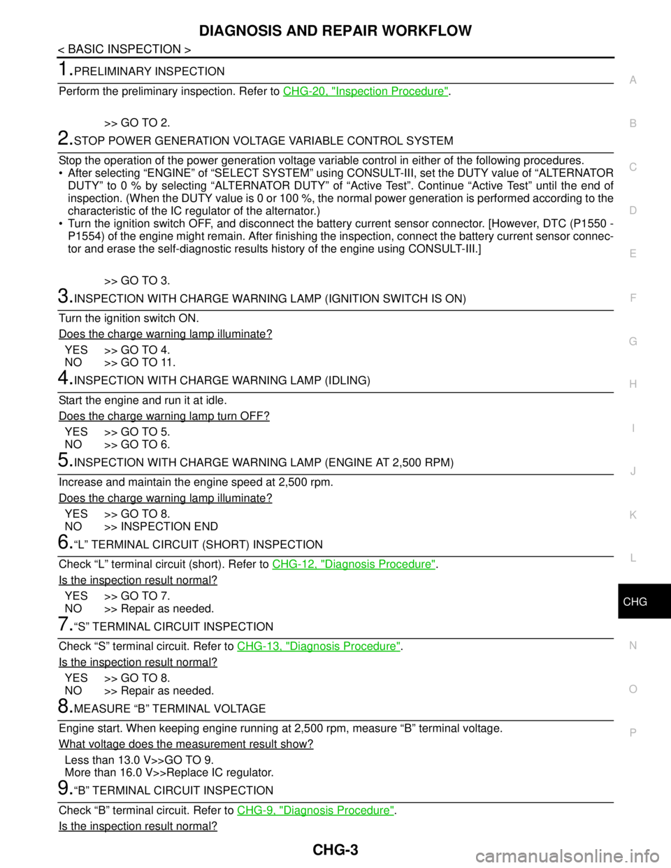
1.PRELIMINARY INSPECTION
Perform the preliminary inspection. Refer to CHG-20, "
Inspection Procedure".
>> GO TO 2.
2.STOP POWER GENERATION VOLTAGE VARIABLE CONTROL SYSTEM
Stop the operation of the power generation voltage variable control in either of the following procedures.
• After selecting “ENGINE” of “SELECT SYSTEM” using CONSULT-III, set the DUTY value of “ALTERNATOR
DUTY” to 0 % by selecting “ALTERNATOR DUTY” of “Active Test”. Continue “Active Test” until the end of
inspection. (When the DUTY value is 0 or 100 %, the normal power generation is performed according to the
characteristic of the IC regulator of the alternator.)
Turn the ignition switch OFF, and disconnect the battery current sensor connector. [However, DTC (P1550 -
P1554) of the engine might remain. After finishing the inspection, connect the battery current sensor connec-
tor and erase the self-diagnostic results history of the engine using CONSULT-III.]
>> GO TO 3.
3.INSPECTION WITH CHARGE WARNING LAMP (IGNITION SWITCH IS ON)
Turn the ignition switch ON.
Does the charge warning lamp illuminate?
YES >> GO TO 4.
NO >> GO TO 11.
4.INSPECTION WITH CHARGE WARNING LAMP (IDLING)
Start the engine and run it at idle.
Does the charge warning lamp turn OFF?
YES >> GO TO 5.
NO >> GO TO 6.
5.INSPECTION WITH CHARGE WARNING LAMP (ENGINE AT 2,500 RPM)
Increase and maintain the engine speed at 2,500 rpm.
Does the charge warning lamp illuminate?
YES >> GO TO 8.
NO >> INSPECTION END
6.“L” TERMINAL CIRCUIT (SHORT) INSPECTION
Check “L” terminal circuit (short). Refer to CHG-12, "
Diagnosis Procedure".
Is the inspection result normal?
YES >> GO TO 7.
NO >> Repair as needed.
7.“S” TERMINAL CIRCUIT INSPECTION
Check “S” terminal circuit. Refer to CHG-13, "
Diagnosis Procedure".
Is the inspection result normal?
YES >> GO TO 8.
NO >> Repair as needed.
8.MEASURE “B” TERMINAL VOLTAGE
Engine start. When keeping engine running at 2,500 rpm, measure “B” terminal voltage.
What voltage does the measurement result show?
Less than 13.0 V>>GO TO 9.
More than 16.0 V>>Replace IC regulator.
9.“B” TERMINAL CIRCUIT INSPECTION
Check “B” terminal circuit. Refer to CHG-9, "
Diagnosis Procedure".
Is the inspection result normal?
Page 1106 of 5121
CHG-8
< FUNCTION DIAGNOSIS >
POWER GENERATION VOLTAGE VARIABLE CONTROL SYSTEM
Component Description
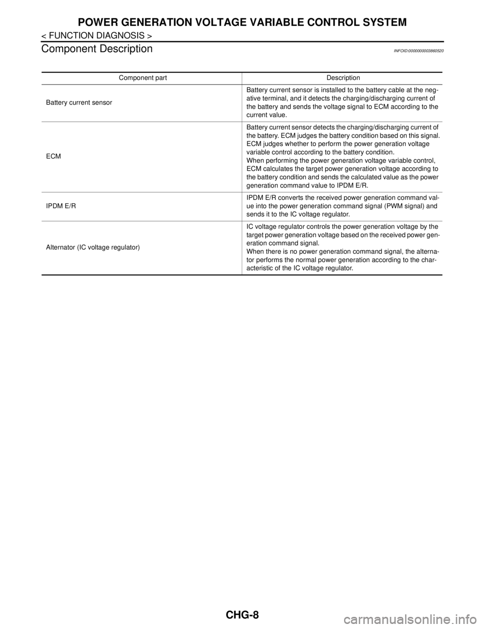
INFOID:0000000003860520
Component part Description
Battery current sensorBattery current sensor is installed to the battery cable at the neg-
ative terminal, and it detects the charging/discharging current of
the battery and sends the voltage signal to ECM according to the
current value.
ECMBattery current sensor detects the charging/discharging current of
the battery. ECM judges the battery condition based on this signal.
ECM judges whether to perform the power generation voltage
variable control according to the battery condition.
When performing the power generation voltage variable control,
ECM calculates the target power generation voltage according to
the battery condition and sends the calculated value as the power
generation command value to IPDM E/R.
IPDM E/RIPDM E/R converts the received power generation command val-
ue into the power generation command signal (PWM signal) and
sends it to the IC voltage regulator.
Alternator (IC voltage regulator)IC voltage regulator controls the power generation voltage by the
target power generation voltage based on the received power gen-
eration command signal.
When there is no power generation command signal, the alterna-
tor performs the normal power generation according to the char-
acteristic of the IC voltage regulator.
Page 1116 of 5121
CHG-18
< PRECAUTION >
PRECAUTIONS
PRECAUTION
PRECAUTIONS
Precaution for Supplemental Restraint System (SRS) "AIR BAG" and "SEAT BELT
PRE-TENSIONER"
INFOID:0000000003860531
The Supplemental Restraint System such as “AIR BAG” and “SEAT BELT PRE-TENSIONER”, used along
with a front seat belt, helps to reduce the risk or severity of injury to the driver and front passenger for certain
types of collision. Information necessary to service the system safely is included in the “SRS AIRBAG” and
“SEAT BELT” of this Service Manual.
WARNING:
• To avoid rendering the SRS inoperative, which could increase the risk of personal injury or death in
the event of a collision which would result in air bag inflation, all maintenance must be performed by
an authorized NISSAN/INFINITI dealer.
Improper maintenance, including incorrect removal and installation of the SRS, can lead to personal
injury caused by unintentional activation of the system. For removal of Spiral Cable and Air Bag
Module, see the “SRS AIRBAG”.
Never use electrical test equipment on any circuit related to the SRS unless instructed to in this Ser-
vice Manual. SRS wiring harnesses can be identified by yellow and/or orange harnesses or harness
connectors.